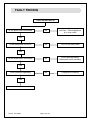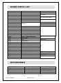
1
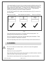
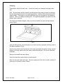
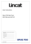
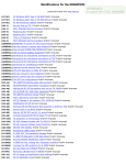
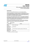
Installation, Operating and Servicing Instructions Opus 700 Electric Filtration Fryers OE7105/F, OE7108/F, OE7113/F Please make a note of your product details for future use: Date Purchased:_________________________ Model Number:__________________________ Serial Number:__________________________ Dealer:_________________________________ _______________________________________ IS 335 ECN 3607 Page 1 of 23 CONTENTS Important Information Warnings and Precautions Technical Data Checklist of Enclosures Installation and Commissioning Operating Instructions Cleaning Servicing, Maintenance and Component Replacement Fault Finding Spare Parts List Accessories Service Information and Guarantee 2 3 3 4 4-11 11-13 13-15 16-18 19-21 22 22 23 IMPORTANT INFORMATION Read these instructions carefully before using this product, paying particular attention to all sections that carry warning symbols, caution symbols and notices. Ensure that these are understood at all times. WARNING! This symbol is used whenever there is a risk of personal injury. CAUTION! This symbol is used whenever there is a risk of damaging your Lincat product. NOTE: This symbol is used to provide additional information, hints and tips. KEEP THIS MANUAL FOR FUTURE REFERENCE IS 335 ECN 3607 Page 2 of 23 WARNINGS AND PRECAUTIONS This appliance must be installed, commissioned and serviced by a qualified person in accordance with national and local regulations in force in the country of installation. If the supply cord is damaged, it must be replaced by the manufacturer, its service agent or similarly qualified person. Ensure that the plug/socket is accessible at all times. Strip plastic coating and clean the appliance before use. During operation parts may become hot - avoid accidental contact. Disconnect this appliance before servicing, maintenance or cleaning. Never attempt to move this appliance when full of hot oil. TECHNICAL DATA OE7105/F Height (mm) Width (mm) Depth (mm) Weight (Kg) Oil capacity to Min. (litres) Maximum load (kg) Power rating (kW) Electrical supply 1N~+E One supply cable 230V 50-60Hz Current rating (A) Electrical supply 1N~+E Two supply cables 230V 50-60Hz Current rating (A) Electrical supply 3N~+E One supply cable 400V 50-60Hz Current rating (A) Electrical supply 3N~+E Two supply cables 400V 50-60Hz Current rating (A) IS 335 ECN 3607 OE7108/F OE7113/F 1050-1100 (900-950 to hob) 400 600 760 89.2 102.0 108.0 2x8 35 2 x 16 2 x 1.0 2 x 1.5 2 x 1.5 2 x 7.0 22.0 2 x 12.0 60.8 N/A N/A N/A 2 x 47.8 2 x 52.2 L1 20.3 L2 20.3 L3 20.3 L1 31.8 L2 31.8 L3 31.8 L1 34.8 L2 34.8 L3 34.8 N/A 2 x L1 15.9 2 x L2 15.9 2 x L3 15.9 2 x L1 17.4 2 x L2 17.4 2 x L3 17.4 Page 3 of 23 CHECK LIST OF ENCLOSURES Warranty card Instructions manual Wire baskets x 2 Lifting hook Batter plate(s) Drain tube Drain bucket Filter bag and frame Filter bag cover Filter pad holder Filter pads x 6 INSTALLATION AND COMMISSIONING This appliance must be earthed. An equipotential bonding terminal is provided to allow cross bonding with other equipment. If replacing the plug connect the terminals as follows: Green and Yellow wire Earth E Blue wire Neutral N Brown wire Live L Means of isolation with at least 3mm contact separation in all poles must be incorporated into the fixed wiring of this appliance. The fixed wiring insulation must be protected by insulated sleeving having a temperature rating of at least 60 Deg C. Supply cords shall be oil resistant, sheathed flexible cable not lighter than ordinary polychloroprene or equivalent elastomer sheathed cord (code 60245 IEC 57) Do not install adjacent to any appliance that has an exposed flame. Site beneath an extraction canopy. If this appliance is fitted with castors, use caution at all times when manipulating or moving, and lock castors when appliance is in position. Install this appliance on a level surface ensuring all vents are unobstructed. Any partitions, walls or furniture must be of non-combustible material. Minimum distances A 100mm B 1000mm – see Fig 1. Do not operate without oil in the tank. IS 335 ECN 3607 Page 4 of 23 Fig 1 Fitting the Stabilising Kit (Fig 2) The stabilising kit must be fitted to prevent accidental toppling of the appliance and to ensure a safe working environment. Fit the adjustable stabiliser centrally to the underside of the front cross member of the appliance (A) using the M5 x 16 hex screws and shake proof washers provided. Ensure the tongue of the bracket is facing rearward and adjusted to sit just off the floor(C). Position the appliance in the intended place. Place the floor plate (D) on the floor so that it fits over the tongue of the stabiliser. IS 335 ECN 3607 Page 5 of 23 Mark locating hole positions of the floor plate. Drill out holes and fit supplied rawlplugs. Screw the floor plate in position using 12g screws. Adjust height position (B) of stabiliser tongue if necessary. Fig 2 Electrical supply and connection Remove the rear panel to gain access to connections. If connecting OE7108/F or OE7113/F appliances to two mains supplies, remove link wires between terminal blocks. The appliance is fitted with a safety cutout switch on the element mounting that disconnects the supply to the element when it is raised in the cleaning position. IS 335 ECN 3607 Page 6 of 23 Component identification Fig 3 OE7108/F 1. Basket support 2. RH element neon 3. Thermostat control 4. Operating mode 5. Pump on 6. RH safety reset 7. LH safety reset 8. Pump reset 9. Filter bag cover 10. Element lifting rod 11. Knurled knob 12. Power on 13. LH element neon 14. Drain valve 15. Filter pad connection 16. Oil bucket IS 335 ECN 3607 Page 7 of 23 Fig 4 OE7113/F 1. Basket support 2. RH power neon 3. RH element neon 4. RH thermostat control 5. Operating mode 6. RH safety reset 7. LH safety reset 8. Pump reset 9. Element lifting rod 10. Knurled knob 11. LH power neon 12. LH element neon 13. LH thermostat control 14. Tank selector 15. Drain valve 16. Pump on 17. Filter pad connection 18. Filter bag cover 19. Oil bucket IS 335 ECN 3607 Page 8 of 23 Fig 5 OE7105/F 1. Basket support 2. LH element neon 3. RH element neon 4. RH thermostat control 5. Pump on 6. Operating mode 7. LH safety reset 8. Pump reset 9. RH safety reset 10. Oil bucket 11. Knurled knob 12. Power on neon 13. LH thermostat control 14. Tank selector 15. Drain valves 16. Filter pad connector 17. Filter bag cover IS 335 ECN 3607 Page 9 of 23 Commissioning Ensure that the drain taps are closed, remove the filter pad holder from the oil drain tank and clean the tanks thoroughly with a warm, mild detergent solution. Rinse the tanks, tap and drain pipe and dry thoroughly. Run a small quantity of oil across the bottom of the tanks. Attach the drain elbow and open the drain tap to drain through. Close the drain tap. Ensure a carbon filter pad is securely fitted in the filter pad holder. Place the filter pad holder in the drain tank. Check that the filter pad holder flexible hose is securely fitted to the pump suction quick coupling. Fill the tank with oil between the minimum and maximum levels ( see Technical Data for capacities). With the control knob in the ‘Off’ position and the Operating mode switch in fryer mode, switch on at the isolator – the green neon will illuminate. Turn the control knob to the required temperature – the corresponding amber neon will illuminate. The amber neon will extinguish when temperature is reached, and continue to operate as the element cycles. Operationally check the appliance by setting the thermostat to 190 oC and checking the temperature of the oil at the geometric centre of the tank 25mm below the surface. The temperature should be within +/- 5oC of the set temperature. Filter mode (pumping system) Hot oil – Wear protective clothing, gloves and safety glasses. On twin tank appliances, filter one tank at a time. Set the control knob to the ‘Off’ position and the Operating mode switch to filter mode – the green neon will extinguish. Ensure the filter pad holder tube is connected to the quick release coupling. Open the drain valve and drain the oil. Close the drain valve. Press the ‘Pump on’ momentum switch and hold for 5 seconds, the pump should start and hot oil will start to be pumped back into the fryer tank. The pump will run until all the oil has returned to the tank, and then automatically switch off. *Note: The pump can be turned off at any time by switching the Operating mode switch to fryer mode. IS 335 ECN 3607 Page 10 of 23 Repeat procedure if necessary for the second tank on twin tank appliances. Switch the Operating mode switch to fryer mode – the green neon will light. Ensure that the end user understands how to operate, shutdown and clean the appliance, and is aware of the position of the isolating switch. OPERATING INSTRUCTIONS Only qualified or trained personnel should use this appliance. General advice Always drain product before frying. Ensure water is never introduced into the oil as this will cause splashing and possible overflow from the tank. Do not operate with the dust cover in place. Do not leave the appliance unattended whilst operating. Keep the oil level maintained between the minimum and maximum markers. For maximum efficiency, do not overload the baskets with product as it will result in reduced recovery times, uneven cooking and increase the risk of surge boiling. Oil should be filtered regularly. Old oil has a reduced flashpoint and is more prone to surge boiling. Operation Remove the dust cover and locate it behind the wire basket support at the rear of the tanks. Check that the drain taps are closed and locked. Fill the tank with oil between the minimum and maximum markers on the rear tank wall. Set the Operating mode switch to fryer mode and turn on the power supply at the isolating switch – the green neon indicates power to the appliance. Turn the control knob to the required setting, the amber neon illuminates to indicate operation of the elements. When the amber neon extinguishes, temperature is reached and cooking may begin. The amber neon will cycle as the element operates to maintain oil temperature. IS 335 ECN 3607 Page 11 of 23 Safety thermostat Should the appliance fail to operate, the safety thermostat may need resetting. This is a red button in the cabinet (see Figs 3-5 for location). Allow the appliance to cool and press the button to reset. Should the appliance still fail to operate, consult a qualified engineer. Filtering Hot oil – Wear protective clothing, gloves and safety glasses. On twin tank appliances, filter one tank at a time. Never operate the pump without the carbon filter pad fitted in the holder. Use the correct filter pad – Lincat Part No. OA7937 (30 pack). Set the control knob to the ‘Off’ position. Set the Operating mode switch to filter mode. Fully pull out the oil tank using the handle. Check the filter bag is positioned correctly in the four locating holes within the drain tank. Fit the supplied drain tube, ensuring it is pointing down into the filter bag. Fit the supplied splashguard over the filter bag. Open the drain valve and drain the hot oil. Fully close the drain valve. See Fig 6 for drain valve operation. Fig 6 IS 335 ECN 3607 Page 12 of 23 In the normal position, the lever is free moving to prevent accidental opening of the valve. Ensure that the handle and drive are never held engaged by any means to always maintain this safety feature. To operate the valve, depress the handle A to engage onto the square drive B and turn to open or close C. Fig 6 shows the various valve positions across the full range of appliances. For OE7105/F and OE7113/F models, use the tank selector (Fig 7) to return oil to the correct tank. Return oil to LH tank Never operate in this position Return oil to RH tank Fig 7 Press and hold the pump switch for 5 seconds until the pumping starts – the pumping will stop automatically when completed. Remove the splashguard, drain tube, filter bag, batter plate and baskets. These may all be cleaned in a dishwasher if desired. Return the Operating mode switch to fryer mode and push the drain tank back in. CLEANING Do not use a water jet or steam cleaner, and do not immerse this appliance. Draining the oil Allow the oil to cool to at least 55oC. Screw the drain elbow onto the drain valve and place a suitable container under the outlet of the elbow. Open the drain valve (Fig 6). Once drained, close the tap to the free moving position and unscrew the elbow. IS 335 ECN 3607 Page 13 of 23 Cleaning Food debris can be a health risk – ensure the tanks are cleaned thoroughly after use. N.B. The elements can be raised from the tanks to allow easy access for cleaning. As the elements are raised to the parking position, a safety switch disconnects the power supply. The power is reconnected when they are returned to the operating position. This is an additional safeguard – the appliance must be isolated from the supply whilst cleaning. Lift off the wire basket support, undo the knurled knobs and remove the element cover (Fig 8). Fig 8 Using the lifting hook, raise elements out of tank by lifting upwards until they latch in the parked position (Fig 9). Remove any debris from the bottom of the tank and wash the tanks, hobtop, basket support and cover plate with warm water and mild detergent. Do not use abrasive materials. Remove and wash the drain elbow. Clean the taps thoroughly using a suitable brush. Rinse out the tank and drain taps. Dry thoroughly and flush with a small quantity of cooking oil to remove traces of water. IS 335 ECN 3607 Page 14 of 23 Fig 9 Close the drain taps into the safe position. Release the filter pad holder from the quick release coupling and remove the drain tank from the fryer. Remove the filter pad from the holder and discard. Clean all items through the dishwasher. To lower the elements again, first lift slightly and then depress the latch button located in the hobtop (Fig 9 A). Replace the element cover and basket support. If the tanks are not to be refilled directly, protect them with a thin layer of cooking oil. Baskets The basket may be cleaned in a dishwasher. IS 335 ECN 3607 Page 15 of 23 SERVICING, MAINTENANCE AND COMPONENT REPLACEMENT All servicing, maintenance and component replacement on this appliance should be carried out by one of our recommended service engineers. Routine service Carry out a general check of the installation, paying particular attention to the following: Correct rating of supply cable. Installation of isolation switch. Operation of all components. Particular operation of safety thermostats. Correct operation of element cutout switch. Check the pump operation, the quick release coupling and plug connection and flexible hose condition, and that there is no evidence of leaks on the filtration circuit. Component replacement Control thermostat Drain the tank, remove the small gland assembly nut, unclip and withdraw the thermostat phial. Remove the control knob. Undo the control panel retaining screws and slide the panel downwards to remove it. Remove the screws retaining the thermostat to the control panel and fit the new thermostat. Reassemble in the reverse order. Safety thermostat Remove the basket support and element cover (Fig 8). Remove the rear cover from the appliance. Consult Fig 10. IS 335 ECN 3607 Page 16 of 23 Fig 10 Remove the capillary cover bracket (A). Unscrew the thermostat from the back panel. Raise the elements and unclip the thermocouple phial and the capillary from the element legs. Unhook the capillary (C) from the cut out in the hobtop (B), noting whether the coil is wound LH or RH around the support tube (D). Fit the new thermostat and reassemble in the reverse order, ensuring that a 4 – turn coil diameter of 15-20mm is wound in the same direction as the one previously removed from the support tube. Contactor Remove the rear cover and unclip the contactor. IS 335 ECN 3607 Page 17 of 23 Connect the cables to the new contactor. Clip in the new contactor and refit the rear cover. Safety cut out Remove the rear cover. Locate the safety cutout assembly at the top adjacent to the element terminals and remove the screws holding the cutout to the bracket. Connect cables to new cutout, screw on new cutout and replace rear cover. Check cutout operates correctly. Element Remove the wire basket support and element cover. Remove the rear cover. Remove the flue panel to access the element connections and fixing nuts. Fit the new element and reassemble in the reverse order, use a silicone seal to block the keyhole slot in the element swivel plate. Pump/Motor unit Remove the rear panel, doors and LH side panel. Undo the control panel and support. Disconnect the pump inlet and outlet pipes. Remove the cable connections. Undo the 4 motor mounting bolts and remove the pump/motor unit. Reassemble in reverse order. Pressure switch Remove the rear panel. Disconnect the sensing line pipe from the pressure switch. Remove the electrical connections. Remove the pressure switch. Reassemble in reverse order. IS 335 ECN 3607 Page 18 of 23 FAULT FINDING Fryer will not heat up Is the green neon illuminated No Check the mains isolator and fuse. Check appliance is in fryer mode No Turn on the thermostat No Check whether safety thermostat needs resetting No Change the contactor Yes Is the thermostat turned on Yes Is the amber neon illuminated Yes Is the contactor operating Yes Check the element IS 335 ECN 3607 Page 19 of 23 Filtration pump will not work Is the appliance in fryer mode (green neon illuminated) Yes Switch appliance to filter mode Yes Reset thermal trip (see Fig 10) No Correctly fit the pipe to the coupling Yes Replace filter pad or unblock No Has the pump motor thermal trip switch activated No Is the filtration return pipe correctly fitted Yes Is the filter blocked No Consult a qualified engineer IS 335 ECN 3607 Page 20 of 23 Fig 11 Thermal trip reset – Fig 11 A. NB Access through door - side only removed for clarity. IS 335 ECN 3607 Page 21 of 23 SPARE PARTS LIST Part Number BA82 BA83 CA109 CA112 CA113 CO215 DR06 EL180 EL185 EL220 FB03 FP06 HA77 HA78 HO102 KN146 KN206 KN225 LE14 LE37 NE39 NE40 OA7937 OP01 PS03 SW34 SW35 SW38 TH59 TH61 TH62 TH78 TH79 Description Basket Basket Castor Braked castor Un-braked castor Contactor Drawer runner Used on OE7108/F, OE7113/F OE7105/F OE7108/F, OE7113/F All OE7105/F OE7108/F OE7113/F Element Filter bag Filter pad holder Door handle Lid handle Element lifting hook Knob - lifting mechanism Knob - knurled Knob – control thermostat Lens cover Leg Green neon Amber neon 30 pack filter pads Pump/motor Pressure switch Mode switch Pump switch Safety cutout switch Control thermostat Safety thermostat Control thermostat Safety thermostat Control thermostat All All OE7105/F All OE7108/F OE7105/F, OE7108/F OE7105/F OE7113/F ACCESSORIES Part Number OA7937 BA122 BA83 OA7954 IS 335 ECN 3607 Description Premium carbon filter pads Half size basket Half size basket Splashguards Page 22 of 23 Used on All OE7113/F OE7108/F, OE7105/F All SERVICE INFORMATION For help with the installation, maintenance and use of your Lincat equipment, please contact our service department: UK: 01522 875520 For non-UK customers, please contact your local Lincat dealer All service work, other than routine cleaning should be carried out by one of our authorised service agents. We cannot accept responsibility for work carried out by other persons. To ensure your service enquiry is handled as efficiently as possible, please tell us: Brief details of the problem Product code All available on serial plate Type number Serial number Lincat reserve the right to carry out any work under warranty, given reasonable access to the appliance, during normal working hours, Monday to Friday, 08:30 to 17:00. GUARANTEE This unit carries a comprehensive UK mainland 2 year warranty. The guarantee is in addition to, and does not diminish your statutory or legal rights. The guarantee does not cover: Accidental damage, misuse or use not in accordance with the manufacturer’s instructions Consumable items (such as filters, glass, bulbs, slot toaster elements and door seals.) Damage due to incorrect installation, modification, unauthorised service work or damage due to scale, food debris build-up, etc. The manufacturer disclaims any liability for incidental, or consequential damages. Attendance is based on reasonable access to the appliance to allow the authorised technician to carry out the warranty work. Service calls to equipment under warranty will be carried out in accordance with the conditions of sale. Unless otherwise specified, a maximum of 15 minutes of administrative time, not spent directly carrying out servicing work, is provided for within the warranty. Any requirement for staff attending the call to spend greater time than 15 minutes due to administrative requirements, such as on health and safety risk assessments, will be chargeable at the prevailing rate. IS 335 ECN 3607 Page 23 of 23