1
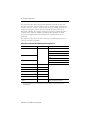
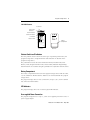
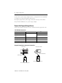
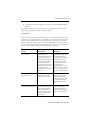
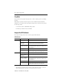
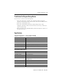
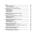
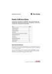
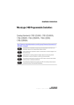
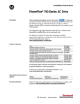
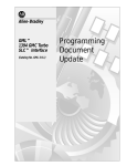
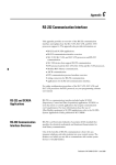
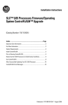
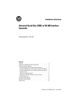
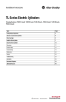
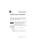
Installation Instructions
Program Storage Device
Catalog Number 1747-PSD, Series D
Topic
Page
Important User Information
2
Safety Considerations
3
Environnements dangereux
3
Overview
3
Selector Switch and Pushbutton
5
Battery Compartment
5
LED Indicators
5
User-supplied Power Connection
5
Connect the Program Storage Device
6
Apply Power to the Program Storage Device
7
Use the Program Storage Device
7
Program Transfer Mode between the Program Storage Device and Controller
7
Program Transfer Mode between the Program Storage Device and Industrial
Programming Station
13
Memory Module Mode
15
Clear Memory Mode
16
Off/Next Command - All Modes
17
Sleep Mode
18
Interpret the LED Indicators
18
Troubleshoot the Program Storage Device
19
Specifications
19
Additional Resources
20
Publication 1747-IN001C-EN-P - May 2006
2
Program Storage Device
Important User Information
Solid state equipment has operational characteristics differing from those of electromechanical equipment.
Safety Guidelines for the Application, Installation and Maintenance of Solid State Controls (publication
SGI-1.1 available from your local Rockwell Automation sales office or online at
http://literature.rockwellautomation.com) describes some important differences between solid state
equipment and hard-wired electromechanical devices. Because of this difference, and also because of the
wide variety of uses for solid state equipment, all persons responsible for applying this equipment must
satisfy themselves that each intended application of this equipment is acceptable.
In no event will Rockwell Automation, Inc. be responsible or liable for indirect or consequential damages
resulting from the use or application of this equipment.
The examples and diagrams in this manual are included solely for illustrative purposes. Because of the many
variables and requirements associated with any particular installation, Rockwell Automation, Inc. cannot
assume responsibility or liability for actual use based on the examples and diagrams.
No patent liability is assumed by Rockwell Automation, Inc. with respect to use of information, circuits,
equipment, or software described in this manual.
Reproduction of the contents of this manual, in whole or in part, without written permission of Rockwell
Automation, Inc., is prohibited.
Throughout this manual, when necessary, we use notes to make you aware of safety considerations.
WARNING
IMPORTANT
ATTENTION
Identifies information about practices or circumstances that can cause an explosion in
a hazardous environment, which may lead to personal injury or death, property
damage, or economic loss.
Identifies information that is critical for successful application and understanding of
the product.
Identifies information about practices or circumstances that can lead to personal injury
or death, property damage, or economic loss. Attentions help you to identify a hazard,
avoid a hazard, and recognize the consequences.
SHOCK HAZARD
Labels may be located on or inside the equipment, for example, a drive or motor, to
alert people that dangerous voltage may be present.
BURN HAZARD
Labels may be located on or inside the equipment, for example, a drive or motor, to
alert people that surfaces may be at dangerous temperatures.
Publication 1747-IN001C-EN-P - May 2006
Program Storage Device
3
Safety Considerations
This equipment is suitable for use in Class I, Division 2, Groups A, B, C, and D, or
non-hazardous locations only. The following attention statement applies to use in
hazardous locations.
WARNING
EXPLOSION HAZARD
• Substitution of components may impair suitability for Class I, Division 2.
• Do not replace components or disconnect equipment unless power has been switched
off and the area is known to be non-hazardous.
• Do not connect or disconnect connectors or operate switches while circuit is live unless
the area is known to be non-hazardous.
• All wiring must comply with N.E.C. article 501-4(b).
Environnements dangereux
Cet équipement est conçu pour être utilisé dans des environnements de Classe 1,
Division 2, Groupes A, B, C, D, ou non dangereux. La mise en garde suivante
s’applique à une utilisation dans des environnements dangereux.
MISE EN GARDE
DANGER D’EXPLOSION
• La substitution de composants peut rendre cet équipement impropre à une utilisation en
environnement de Classe 1, Division 2.
• Couper le courant ou s’assurer que l’emplacement est désigné non dangereux avant de
remplacer les composants.
• Couper l’alimentation ou s’assurer que l’environnement est classé non dangereux avant
de brancher ou débrancher des connecteurs ou de faire fonctionner des commutateurs.
Overview
The 1747-PSD Program Storage Device (PSD) is a hand-held program-transfer
device. The PSD provides one-program storage and retrieval for SLC 5/03, 5/04, and
5/05 and MicroLogix 1000, 1100, 1200, and 1500 controllers.(1) The PSD connects to
the RS-232 serial port running DF1 full-duplex communications protocol.
(1)
The names SLC, PLC, and controller are used interchangeably to describe a programmable controller. Industrial
programming station is an industrial-hardened PC-based programming station located in the factory production area.
Publication 1747-IN001C-EN-P - May 2006
4
Program Storage Device
The program storage device supports DF1 full-duplex with CRC or BCC error
detection, 8 data bits, 1 stop bit, and no parity at communication rates 1200 bps,
2400 bps, 4800 bps, 9600 bps, 19200 bps, and 38400 bps. During operation, the
program storage device matches the DF1 communication rate of the SLC or
MicroLogix controller. The program storage device will not communicate with a
controller if the channel is configured for DH485, DF1 half-duplex or ASCII
protocol. Embedded responses and simultaneous communications are not
supported.
The program storage device checks for 19200 bps communication rate first. Use
19200 bps for fastest recognition.
Controllers used with 1747-PSD Program Storage Device
Controller
Series
Operating System
SLC 5/03
Not applicable
OS300
OS301
OS302
SLC 5/04
OS400
OS401
SLC 5/05
OS500
OS501
MicroLogix 1000 Analog
A
MicroLogix 1000 Discrete
A, B, C, D, E, and F
MicroLogix 1100(1)
A
MicroLogix 1200
A, B, and C
MicroLogix 1500, 1764-LSP
MicroLogix 1500, 1764-LRP
A, B, and C
(1)
PC-based industrial programming
station
(1)
Not applicable
B and C
Not applicable
RSLogix 500, A.I. 500 Series, SLC 500
Advanced Programming Software
Recipe data and/or Data Logs stored in Data Log Memory cannot be uploaded or downloaded by the 1747-PSD
programming device.
Publication 1747-IN001C-EN-P - May 2006
Program Storage Device
5
1747-PSD Features
Power Supply
Connector
Red LED Indicator
Green LED Indicator
Push Button
7-30 VDC
250mA max
RS-232 Port
DANGER
EXPLOSION
HAZARD
DO NOT DISCONNECT CONNECTORS
OR OPERATE SWITCHES
UNLESS AREA IS NON-HAZARDOUS
CAT.
SER.
1747-PSD
Error
Complete - OK
Linking
Executing
C
FRN.
3
LISTED IND. CONT. EQ.
C
R
US FOR HAZ. LOC. A196
OPERATING TEMPERATURE
CODE T3C
N223
CLASS I, GROUPS A, B, C, AND D, DIV. 2
EXECUTE
For Class I, Division 2 applications use batteries
only. See Installation Instructions.
Selector Switch
MADE IN U.S.A.
RUN
PROG
TO PLC
MODE CHANGE
FROM PLC
Battery
Compartment
OFF/NEXT CMD
Program Storage Device
For use with the PLC communication protocol of
DF1 Full Duplex only
1747-PSD
Front View
Back View
Selector Switch and Pushbutton
The four-position selector switch selects the type of operation performed by the
program storage device. Program Transfer mode functions are labeled on the
program storage device.
The pushbutton executes the selected function. Memory Module mode, Clear
Memory mode, Program Transfer mode, and Secondary Industrial Programming
Station functions are available using the pushbutton in conjunction with the switch.
Battery Compartment
The battery compartment in the back of the program storage device holds two AAA,
1.5V dc standard or alkaline batteries. Batteries are not included with the program
storage device.
The program storage device is Class I, Division 2, Groups A, B, C, and D certified
only when used with batteries.
LED Indicators
The program storage device has a red and a green LED indicator.
User-supplied Power Connection
The program storage device accepts 7...30V dc user-supplied power from a Class 2
power supply adapter.
Publication 1747-IN001C-EN-P - May 2006
6
Program Storage Device
A 9V dc, Class 2 power supply adapter (120V ac), catalog number 1787-USADPTR,
is available for use with the program storage device.
The adapter plugs into the power supply connection at the top of the module.
For permanent installations, use a power supply adapter.
Connect the Program Storage Device
Connect the program storage device to the controllers with the appropriate cable.
1747-PSD Cable Connection
Controller
Serial Port
With Cable(1)
SLC 5/03, SLC 5/04, and SLC 5/05
Channel 0 RS-232
1747-CP3
MicroLogix 1000, 1100, 1200, and
1500
1761-CBL-PM02
MicroLogix 1500
Channel 1 RS-232
1747-CP3
MicroLogix 1200
PROG/HMI RS-232
1761-CBL-PM02
Industrial Programming Station
COM1 or COM2
1747-CP3
(1)
The cables are not supplied with the program storage device.
Program Storage Device Connected to Controllers
SLC Controller
MicroLogix Controller
1761-CBL-PM02 Cable
1747-CP3 Cable
RUN
RUN
PROG
TO PLC
MODE
FROM PLC
OFF
PROG
TO PLC
MODE
FROM PLC
OFF
Program Storage Device
1747-PSD
Program Storage Device
1747-PSD
1747-PSD Programming Device
Publication 1747-IN001C-EN-P - May 2006
1747-PSD Programming Device
Program Storage Device
7
Apply Power to the Program Storage Device
To apply power, move the selector switch from the OFF/NEXT CMD position to any
desired function selection.
LED Indicators when Applying Power
Red LED Indicator
Green LED Indicator
Indicates
On
Off
an error at power-up.
Flashing
Off
the program storage device is trying to communicate.
Off
On
the program storage device is able to communicate.
Off
Off
the program storage device is in Sleep mode.
Use the Program Storage Device
The program storage device has five modes.
• Program Transfer mode - between program storage device and controller
• Program Transfer mode - between program storage device and industrial
programming station
• Memory Module mode
• Clear Memory mode
• Off/Next Command mode
• Sleep mode
IMPORTANT
When an error occurs during operation, the red LED indicator illuminates
steadily for 30 seconds before the module enters the Sleep mode.
Program Transfer Mode between the Program Storage Device and
Controller
Program Transfer mode allows a program to be transferred between the program
storage device and controller.
Publication 1747-IN001C-EN-P - May 2006
8
Program Storage Device
Program Transfer between the Program Storage Device and Controller
Download
Industrial Programming Station with
RSLogix 500 software,
A.I. 500 software, or Advanced
Programming Software.
Upload
To PLC
PSD
SLC 5/03, 5/04, and 5/05 controller
MicroLogix 1000, 1100, 1200, and 1500 controller
From PLC
Program Transfer between the Program Storage Device and Controller
Switch Position
Function
To PLC
Transfers a new program from the program storage device to the controller. The
controller must be in Remote Program mode or an error will occur.
Mode Change
Toggles the controller mode between Remote Program and Remote Run. When the
program storage device switches the controller to Remote Program, the error bits are
cleared.
From PLC
Transfers a program from the controller to the program storage device. The program
storage device can receive a program regardless of the controller’s operating mode.
If you want to transfer a program to the controller and the controller is not in
Remote Program mode, follow the steps using the mode change command.
1. Without pressing the pushbutton, slide the selector switch from the
OFF/NEXT CMD position to the desired command.
2. Wait until the green LED indicator illuminates steadily.
3. Within 10 seconds after the green LED indicator illuminates steadily, press
the pushbutton.
4. Release the pushbutton within 10 seconds.
While the command is executing, the green LED indicator flashes.
If the green LED indicator and red LED indicator flash simultaneously, refer
to the Incompatibilities section.
When execution is complete, either the green or the red LED indicator
illuminates steadily for 30 seconds. Green indicates a successful transfer and
red indicates a failed transfer.
After 30 seconds, the illuminated LED indicator turns off, and the program
storage device enters the Sleep mode.
Publication 1747-IN001C-EN-P - May 2006
Program Storage Device
9
5. To maximize battery life, slide the selector switch to the OFF/NEXT CMD
position.
To return the controller to the Remote Run mode following a program transfer,
repeat these steps using the mode change command.
Incompatibilities
When a download from the program storage device is commenced, and the target
controller is of an earlier firmware version (Series or OS) than the stored program,
the green and red LED indicators flash simultaneously. This indicates a possible
program incompatibility. Pressing and releasing the EXECUTE pushbutton within 10
seconds after the LED indicators begin flashing allows the possible incompatibility
to be accepted, and the program download operation commences.
If a downloaded program
contains
Then the program storage
device indicates
Use the tables in this section
to determine
file types that are not supported
by the controller
that the download has failed and
after the controller Edit
Resource/Owner Timeout expires
(60 seconds by default), the
controller Fault LED indicator will
flash and the out-of-box default
program will be loaded into
controller memory. (Until the Edit
Resource/Owner Timeout expires,
the controller remains in
download mode and the Fault LED
indicator is off.)
if new file types in the series of
controller file to be downloaded by
the program storage device
causes the download to an earlier
series target controller to fail.
If security, multi-point and F8
floating point files are present,
they can’t be deleted.
Programmable Limit Switch and
String files are optional, so if they
don’t exist in the user program,
they won’t cause the download to
fail.
instructions that are not supported
by the target controller
that the download has completed,
but the controller faults when
attempting to go to Run mode.
if new instruction types in the
series of controller file to be
downloaded by the program
storage device causes an earlier
series target controller to fault
when attempting to go to Run
mode.
a communication driver that is not
supported by the target controller
that the download has completed,
and the controller goes into Run
mode, but that communication
channel configuration remains
unchanged. Message instructions
targeting this communication
channel may fail.
if the communication driver in the
series of controller file to be
downloaded by the program
storage device is supported by the
earlier series target controller.
Publication 1747-IN001C-EN-P - May 2006
10
Program Storage Device
RSLogix 500 software may be used to determine the source of the incompatibility.
In Offline mode, set the controller series/revision to that of the target controller and
observe the errors indicated by the program verification routine.
Refer to Additional Resources for a listing of where you can go to find more
information regarding file types, instructions, and controllers.
Incompatible Controllers
Controller
Controller
OS/Series
File Types
Supported
Instructions
Supported
Comms Supported
SLC 5/03
OS302, Series C,
FRN 10 and later
Security(1)
CEM, DEM, RPC
—
OS302, Series C,
FRN 3...8
—
BTR, BTW, RHC, TDF,
ENC, RMP, FBC, DDT
DF1 Radio Modem
(FRN 6+)
OS302, Series B
—
—
—
DF1 Half-duplex
Master
SLC 5/04
OS302, Series A
Multi-point
SIN, COS, TAN, ASN,
ACS, ATN, LN, LOG,
ABS, DEG, RAD, XPY,
CPT, SWP, SCP
OS301, Series A
Float(2), String
ABL, ACB, ACI, ACL,
ACN, AEX, AHL, AIC,
ARD, ARL, ASC, ASR,
AWA, AWT
—
OS300, Series A
—
—
—
CEM, DEM, RPC
—
(1)
OS401, Series C,
FRN 10 and later
Security
OS401, Series C,
FRN 3...8
—
BTR, BTW, RHC, TDF,
ENC, RMP, FBC, DDT
DF1 Radio Modem
(FRN 6+)
OS401, Series B
—
—
—
OS401, Series A
Multi-point(1)
SIN, COS, TAN, ASN,
ACS, ATN, LN, LOG,
ABS, DEG, RAD, XPY,
CPT, SWP, SCP
DF1 Half-duplex
Master
OS400, Series A
—
—
—
Publication 1747-IN001C-EN-P - May 2006
(1)
Program Storage Device
11
Incompatible Controllers
Controller
Controller
OS/Series
File Types
Supported
Instructions
Supported
Comms Supported
SLC 5/05
OS501, Series C,
FRN 10 and later
Security(1)
CEM, DEM, RPC, EEM
—
OS501, Series C,
FRN 3...8
—
BTR, BTW, RHC, TDF,
ENC, RMP, FBC, DDT
DF1 Radio Modem
(FRN 6+)
OS501, Series B
—
—
—
OS500, Series A
—
—
—
Series F
—
—
—
Series E
—
—
—
Series D
—
—
DF1 Half-duplex Slave
Series C
—
MSG
DH-485
Series B
—
—
—
Series A
—
—
—
MicroLogix 1000
Analog
Series A
—
—
—
MicroLogix 1100
Series A
—
—
—
MicroLogix 1200
Series C, FRN 4+
Pls, Float(2)
CPW, RTA, GCD, ABS,
SCP with FP (FRN 6+)
MicroLogix 1000
Discrete
• DF1 Half-duplex
Master (FRN 7+)
• DF1 Radio
Modem (FRN 7+)
• Modbus RTU
Master (FRN 8+)
Series B, FRN 3
—
ABL, ACB, ACI, ACN,
AEX, AHL, ARD, ARL,
ASC, ASR, SWP
—
Series A, FRN
1...2
—
—
—
Publication 1747-IN001C-EN-P - May 2006
12
Program Storage Device
Incompatible Controllers
Controller
Controller
OS/Series
File Types
Supported
Instructions
Supported
MicroLogix 1500
LSP
Series C, FRN 6+
Pls, Float(2)
CPW, RTA, GCD, ABS,
RCP, SCP with FP (FRN
7+)
Comms Supported
• DF1 Half-duplex
Master (FRN 8+)
• DF1 Radio
Modem (FRN 8+)
• Modbus RTU
Master (FRN 9+)
MicroLogix 1500
LRP
Series B, FRN
4...5
String
—
Modbus RTU Slave
Series A, FRN
1...3
—
—
—
Series C, FRN 6+
Pls, Float(2)
CPW, RTA, GCD, ABS,
RCP, SCP with FP (FRN
7+)
• DF1 Half-duplex
Master (FRN 8+)
• DF1 Radio
Modem (FRN 8+)
• Modbus RTU
Master (FRN 9+)
Series B, FRN
4...5
—
(1)
File cannot be deleted.
(2)
F8 file cannot be deleted by RSLogix 500 software.
Publication 1747-IN001C-EN-P - May 2006
—
—
Program Storage Device
13
Program Transfer Mode between the Program Storage Device and
Industrial Programming Station
Program Transfer mode allows a program to be transferred between the program
storage device and the industrial programming station.
Program Transfer between the Program Storage Device and Industrial
Programming Station
Download
Industrial Programming Station with
RSLogix 500 software,
A.I. 500 software, or Advanced
Programming Software.
Upload
To PLC
PSD
SLC 5/03, 5/04, and 5/05 controller
MicroLogix 1000, 1100, 1200, and 1500 controller
From PLC
Program Transfer between the Program Storage Device and Industrial
Programming Station
Switch Position
Function
To PLC
Transfers a program from the industrial programming station to the program storage
device (DOWNLOAD).
From PLC
Transfers a program from the program storage device to the industrial programming
station (UPLOAD).
IMPORTANT
There are two unique operating sequences defined for program
upload/download between the industrial programming station and the program
storage device. The primary operational sequence used with RSLogix software,
V5.20 or later varies slightly from the secondary procedure (typically) used with
earlier RSLogix software versions, and with other programming software
packages.
The primary sequence allows for convenient, unconditional transfer of the program,
but does not guarantee OS revision control upon transfer to the target controller.
Transfer of an incompatible program to the controller will result in loss of the
resident user program, and may result in a failed download or a controller fault
when the controller is placed in Run mode.
The secondary sequence, designed for use with earlier programming packages
(also functional with RSLogix software, V5.20 or later), uses a stored controller
identity to guarantee OS revision control and will disallow program transfer
operations that could result in improper controller operation (due to unsupported
functions included in the user program).
Publication 1747-IN001C-EN-P - May 2006
14
Program Storage Device
New program storage device units are loaded with the 5/04 controller identity as
default. If the program storage device is to be used with a different controller and
the secondary procedure will be used, the desired controller identity must be
transferred to the program storage device (using the Program Transfer Mode Controller From PLC command) from the desired controller type (5/03 controller,
for example). The program storage device maintains the stored controller identity
even when the program storage device is cleared. The only way to change the
program storage device identity is to execute a program transfer operation from the
desired controller (Program Transfer Mode - Controller From PLC command).
To transfer a program to the industrial programming station:
1. Start the applicable programming software on the Industrial Programming
Station. Configure for RS-232, DF1 full-duplex communications. Select 19200
baud and CRC error checking. If applicable, disable autobrowsing (RSWho).
2. Primary - for RSLogix software, V5.20 or later: Without pressing the
pushbutton, slide the selector switch from the OFF/NEXT CMD position to
the desired command.
The red LED indicator may blink while the program storage device attempts
to connect. When the program storage device detects RSLinx software as the
connected device, the green LED indicator will illuminate steadily.
Secondary - for RSLogix software, A.I. 500 software or Advanced
Programming software.
a. With the pushbutton depressed, slide the selector switch from the
OFF/NEXT CMD position to the desired command.
Continue holding down the pushbutton while the program storage
device attempts to establish communications (the red LED indicator may
blink during this process).
b. When the green LED indicator illuminates steadily, release the
pushbutton (within 10 seconds).
3. Within 10 seconds after the green LED indicator illuminates steadily, depress
the pushbutton.
4. Release the pushbutton within 10 seconds. Wait for the green LED indicator
to illuminate steadily.
5. Within 30 seconds, the upload or download transfer must begin. Issue the
upload or download command from the industrial programming station.
Publication 1747-IN001C-EN-P - May 2006
Program Storage Device
WARNING
15
In all cases, executing a download command will clear the program currently
stored in the program storage device.
While the command is executing, the green LED indicator flashes.
Completion of the transfer is indicated by the programming software
package, or by a steadily illuminated LED indicator on the program storage
device. Green indicates a successful transfer and red indicates a failed
transfer.
After 30 seconds, the illuminated LED indicator turns off and the program
storage device enters the Sleep mode.
6. To maximize battery life, slide the selector switch to the OFF/NEXT CMD
position.
Memory Module Mode
Memory Module mode allows a program to be transferred between the memory
module and controller. The Memory Module mode cannot be used with the
MicroLogix 1000 controller because the controller does not have a memory module
feature.
Memory Module Mode
Switch Position
Function
To PLC
Transfers a program from the memory module to the controller.(1) The controller must
be in Remote Program mode or an error will occur.
Mode Change
Reserved for Clear Memory mode indication.
From PLC
Transfers a program from the controller to the memory module.
(1)
Write-only protection is not supported. The memory module can be reprogrammed with another update.
If you want to transfer a program to the controller and the controller is not in
Remote Program mode, first follow the Program Transfer Mode - Controller
procedure using the mode change command.
1. Hold the pushbutton down and move the selector switch from the
OFF/NEXT CMD position to the desired command, either to PLC or from
PLC.
Publication 1747-IN001C-EN-P - May 2006
16
Program Storage Device
Continue holding the pushbutton until the green LED indicator turns on.
2. Within 10 seconds after the green LED indicator illuminates steadily, release
the pushbutton.
The green LED indicator turns off.
3. Within 10 seconds, press the pushbutton again.
4. Release the pushbutton within 10 seconds.
While the command is executing, the green LED indicator flashes.
When execution is complete, either the green or the red LED indicator
illuminates steadily for 30 seconds. Green indicates a successful transfer and
red indicates a failed transfer.
After 30 seconds, the illuminated LED indicator turns off and the program
storage device enters the Sleep mode.
5. To maximize battery life, slide the selector switch to the OFF/NEXT CMD
position.
To return the controller to the Remote Run mode following a memory module
transfer, follow the Program Transfer Mode - Controller procedure using the Mode
Change command.
Clear Memory Mode
Clear Memory mode allows a program to be cleared in the controller or program
storage device.
Clear Memory Mode
Switch Position
Function
To PLC
Clears the program from the controller’s memory. The controller must be in Remote
Program mode or an error will occur.
Mode Change
Reserved for Clear Memory mode indication.
From PLC
Clears the program from the program storage device’s memory. Maintains stored
controller identity.
Publication 1747-IN001C-EN-P - May 2006
Program Storage Device
17
If you want to clear the controller’s memory and the controller is not in Remote
Program mode, first follow the Program Transfer Mode - Controller procedure using
the mode change command.
1. Hold the pushbutton down and slide the selector switch from OFF/NEXT
CMD to mode change to select Clear Memory mode.
Continue holding down the pushbutton until the green LED indicator
illuminates steadily to indicate program storage device readiness.
2. Release the pushbutton within 10 seconds.
3. Wait for the green LED indicator to turn off.
4. Within 10 seconds, press the pushbutton.
5. Release the pushbutton within 10 seconds.
6. Slide the selector switch to the desired command, either To PLC or From
PLC.
7. Within 10 seconds, press the pushbutton.
8. Release the pushbutton within 10 seconds.
The green LED indicator flashes while the command is executing.
When execution is complete, either the green or the red LED indicator
illuminates steadily for 30 seconds. Green indicates a successful transfer and
red indicates a failed transfer.
After 30 seconds, the LED indicator will turn off, and the program storage
device enters the Sleep mode.
9. To maximize battery life, slide the selector switch to the OFF/NEXT CMD
position.
To return the controller to the Remote Run mode following a clear memory
function, follow the Program Transfer Mode - Controller procedure using the mode
change command.
Off/Next Command - All Modes
Off/Next Command turns off the program storage device or readies it for the next
command.
Publication 1747-IN001C-EN-P - May 2006
18
Program Storage Device
Sleep Mode
Sleep mode lets the program storage device conserve battery power by shutting
itself off.
Following an operation, either the green or the red LED indicator illuminates
steadily for 30 seconds before the program storage device enters the Sleep mode.
To exit Sleep mode:
1. Turn the switch to OFF/NEXT CMD position.
2. Follow procedure for next command.
Interpret the LED Indicators
The program storage device has a red and a green LED indicator.
LED Indicators
LED Indicator
Status
Indicates
Red
On at power-up
Power-up error.
Flashing(1) (green LED
indicator off)
Linking. The program storage device is attempting to
Flashing(1) (coincident
with green LED indicator)
Download of program to earlier Series/OS level controller has
been requested. Program storage device is waiting for user
acknowledgement.
On after operation
Unsuccessful operation.
Off after 30 s
Program storage device is in Sleep mode. To exit Sleep mode,
Turn the program storage device off and apply power.
On at power-up
Program storage device is ready.
Flashing(1) (red LED
indicator off)
Operation is in progress.
Flashing(1) (coincident
with red LED indicator)
Download of program to earlier Series/OS level controller has
been requested. Program storage device is waiting for user
acknowledgement.
On after operation
Successful operation.
Off after 30 s
Program storage device is in Sleep mode. To exit Sleep mode,
turn the program storage device off and apply power.
Green
communicate.(2) Check communication parameters.
(1)
The on/off flashing rate of the LED indicator could range from approx. 0.1 to 1 second.
(2)
While applying power, the program storage device attempts to establish communication for approx. 10 seconds, after
which the red LED indicator turns solid for approx. 30 seconds and the unit enters the Sleep mode.
Publication 1747-IN001C-EN-P - May 2006
Program Storage Device
19
Troubleshoot the Program Storage Device
If an error has occurred, try the following items.
• Check the mode of the controller. The controller should be in Remote
Program or Remote Run mode. The keyswitch must be in the REM position.
• Check the communication cable.
• Check the communication parameters. Target settings must be DF1
full-duplex with CRC or BCC, at rates from 1200 to 38400 bps, 8 data bits, 1
stop bit, and no parity.
• Move the switch to the OFF/NEXT CMD position and begin the sequence of
operation from step 1.
Specifications
Program Storage Device - catalog number 1747-PSD
Attribute
Value
Memory Size, Max
64 K
Supported Communication Rates
38400, 19200, 9600, 4800, 2400, and 1200 bps
Memory Module
EEPROM
Operating Power, Max
7...30V dc, 250 mA, or (2) AAA batteries
Dimensions (HxWxD), Approx.
116 x 66 x 28 mm (4.58 x 2.60 x 1.10 in.)
Weight
0.45 kg (1 lb)
Environmental Specifications
Attribute
Value
Temperature, operating
0...60 °C (32...140 °F)
Temperature, storage
-40...85 °C (-40...185 °F)
Humidity, non-condensing
5 to 95%
Vibration
10 to 57 Hz, 0.3 mm (0.012 in.) peak-to-peak displacement
57 to 500 Hz, 2.0 g
Shock, operating
30.0 g
Shock, non-operating
50.0 g
Free Fall (drop test)
Portable, 2.0 kg (4.4 lb) or less at 1.0 m (39.37 in.) (two drops)
Noise Immunity
NEMA Standard ICS 2-230
Publication 1747-IN001C-EN-P - May 2006
Certifications
Certification(1)
Agency Certification
(when product or packaging is
marked)
(1)
Value
• UL and C-UL Listed
• Class I, Division 2, Groups A, B, C, D (with batteries only)
• CE/C-Tick compliant for all applicable directives
See the Product Certification link at http://ab.com for Declaration of Conformity, certificates, and other certification details.
Additional Resources
Additional resources related to the Program Storage Device are available.
For
Refer to
Publication Number
A reference manual that contains status file
data and instruction set information your
modular SLC 500 system.
SLC 500 Instruction Set
Reference Manual
1747-RM001
A reference manual that contains status file
data and instruction set information for your
MicroLogix 1000 controller.
MicroLogix 1000 Programmable
Controllers User Manual
1761-UM003
A reference manual that contains status file
data and instruction set information for your
MicroLogix 1100 controller.
MicroLogix 1100 Programmable
Controllers Instruction Set
Reference Manual
1763-RM001
A reference manual that contains status file
data and instruction set information for
MicroLogix 1200 and 1500.
MicroLogix 1200 and 1500
Instruction Set Reference
Manual
1762-RM001
You can view or download publications at
http://literature.rockwellautomation.com. To order paper copies of technical
documentation, contact your local Rockwell Automation distributor or sales
representative.
Allen-Bradley, ControlLogix, SLC, PLC, MicroLogix, and RSLinx are trademarks of Rockwell Automation, Inc.
Trademarks not belonging to Rockwell Automation are property of their respective companies.
Publication 1747-IN001C-EN-P - May 2006
Supersedes Publication 1747-IN001B-EN-P - November 2001
PN 40071-080-01(3)
Copyright © 2006 Rockwell Automation, Inc. All rights reserved. Printed in the U.S.A.