1
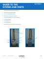
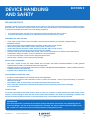
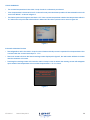
ORBIS I SCALP COOLER
INSTRUCTIONS FOR USE
BEFORE OPERATING THE SCALP COOLER, IT IS
IMPORTANT THAT THIS MANUAL BE FULLY READ AND
UNDERSTOOD BY ALL OPERATORS OF THE SYSTEM.
0473
IFU Orbis I
Issue 3 May 2013
1
INDEX
SECTION NO.
1
INTRODUCTION TO SCALP COOLING
2
DEVICE DESCRIPTION
3
INTENDED USE/INDICATIONS FOR USE
4CONTRAINDICATIONS
5
WARNINGS AND PRECAUTIONS
6
SIDE EFFECTS
7
EQUIPMENT SUPPLIED
8
GUIDE TO THE SYSTEM AND PARTS
9
DEVICE HANDLING AND SAFETY
10
QUICK RELEASE COUPLINGS
11
COOLING CAPS INFORMATION
12
PATIENT CAP SIZE SELECTION
13
SYSTEM PREPARATION PROCEDURE
14
CAP PRE-COOLING
15
PATIENT PREPARATION
16
CAP FITTING TO THE PATIENT
17
PRE-INFUSION SCALP COOLING
18
POST INFUSION COOLING
19
TEMPORARY DISCONNECTION DURING COOLING: BATHROOM VISITS
20
COMPLETION OF POST INFUSION SCALP COOLING
21
CAP REMOVAL
22
CAP AND COVER CLEANING
23
CAP STORAGE
24
DISPOSAL OF DAMAGED OR CONTAMINATED COMPONENTS
25
PERIODIC MAINTENANCE
26
THE INBUILT HELP FUNCTION
27
MATERIAL SAFETY AND DATA
28
MANUFACTURER CONTACT DETAILS
IFU Orbis I
Issue 3 May 2013
PAGE NO.
3
4
5
6
7
8
9
10
11
14
15
16
18
20
21
22
24
26
28
29
30
31
32
33
34
35
36
37
2
INTRODUCTION TO
SCALP COOLING
SECTION 1
Hair loss (alopecia) is recognised as one of the most common and distressing side-effects of chemotherapy.
Chemotherapy drugs rely for their effectiveness in treating cancer on their ability to attack rapidly dividing
malignant cells. However, these drugs will also attack healthy hair follicle cells (around 85 – 90% of which are
normally in a state of rapid growth at any one time), causing partial or total atrophy of the hair root, which can
result in weakening or fracture of the hair shaft.
Preventing or reducing hair loss can result in increased self-confidence and positive attitude in patients – which
are widely recognised as beneficial in the fight against cancer. Scalp cooling aims to reduce chemotherapyinduced hair loss by causing constriction of the blood vessels in the scalp, thereby reducing the amount of
chemotherapy drugs delivered to the hair follicles. There is also a reduction in the local metabolic rate, which
reduces cellular uptake of the drug at the hair follicle. It is important for the effectiveness of this technique that
the scalp remains cold during the time that the drugs are at their highest concentration in circulating blood.
In a single treatment session the scalp is cooled for a short period before chemotherapy infusion, during infusion
and over a specific period following infusion. The user has the option of beginning the pre-infusion scalp cooling
with fitting a warm cap or a pre-cooled cap to the scalp. This decision can be made upon personal preferences.
It is important to note that there are subtle differences between the procedures which should be followed when
the user is starting with a warm cap compared to a pre-cooled cap and therefore care should be taken to
ensure that the correct section of this user manual is being referred to in each case. When the user begins the
treatment session wearing a warm cap the cap cools down whilst fitted to the scalp which increases the amount
of time it takes for the scalp to cool down. Consequently a slightly longer pre-infusion scalp cooling duration is
recommended for treatment sessions in which a warm cap is initially fitted to the user. Although not proven, it
is expected that the success of the treatment is not be affected by whether the cooling treatment commences
with the fitting of a warm cap or a pre-cooled cap if the correct recommended procedure is followed.
IFU Orbis I
Issue 3 May 2013
3
DEVICE DESCRIPTION
SECTION 2
The Orbis I Scalp Cooler is a compact, mobile refrigeration unit, which circulates a refrigerated liquid coolant,
at low pressure, through a special cooling cap that is positioned on the patient’s head. The circulation of the
refrigerated coolant through the cap extracts heat from the patient’s scalp and maintains it at the optimum
temperature for scalp cooling.
IFU Orbis I
Issue 3 May 2013
4
INTENDED USE/
INDICATIONS FOR USE
SECTION 3
The Orbis I Scalp Cooler is indicated for use to reduce chemotherapy-induced hair loss in cancer patients
receiving systemic chemotherapy with alopecia causing chemotherapy agents.
The Orbis I Scalp Cooler is intended for use by appropriately qualified healthcare professionals who have been
trained in correct operation of the device by a representative of Paxman Coolers.
Patients and users/operators should be aware of the following:
•Hair loss is a possible side effect of chemotherapy.
•The treatment success rates vary from patient to patient and with different drug regimens
being administered.
•Patients cannot be guaranteed they will not lose any or all of their hair.
•Patients may experience a headache during treatment
•Some patients may experience feeling cold during the treatment
•Some patients may experience feeling light headed after the cooling cap has been removed
•Patients may visit the bathroom during the treatment
Information on the above indications is available for users and patients
IFU Orbis I
Issue 3 May 2013
5
CONTRAINDICATIONS
SECTION 4
• Haematological malignancies (leukaemia, non Hodgkins and other generalised lymphomas)
• Cold allergy
• Cold agglutinins
• Manifest scalp metastases – see section
• Imminent bone marrow ablation chemotherapy
• Imminent skull irradiation
IFU Orbis I
Issue 3 May 2013
6
WARNINGS AND
PRECAUTIONS
SECTION 5
• It cannot be guaranteed that scalp cooling will prevent all patients undergoing chemotherapy from losing
any or all of their hair. The success rate of scalp cooling in reducing chemotherapy-induced hair loss varies
from patient to patient and according to the chemotherapy regime administered.
• The Orbis I Scalp Cooler should only be used by appropriately qualified healthcare professionals who have
been trained in operation of the device.
• DO NOT ALLOW ANY LIQUIDS TO BE PLACED ON THE SCALP COOLER OR NEAR THE TOUCH SCREEN
CONTROLLER, INCLUDING THE COOLING CAPS.
• AVOID USE IN AMBIENT TEMPERATURES OF OVER 30°C
NOTE: Warnings and precautions concerning specific aspects of the operation of the Orbis I Scalp Cooler are
described within the relevant sections of this user manual.
IFU Orbis I
Issue 3 May 2013
7
SIDE EFFECTS
SECTION 6
Known side-effects associated with scalp cooling therapy include:
• discomfort due to feeling cold;
• headache;
• light-headedness or dizziness;
• nausea.
IFU Orbis I
Issue 3 May 2013
8
EQUIPMENT SUPPLIED
SECTION 7
Equipment consists of:
1. Electronically operated refrigeration unit complete with power cable.
2. 1 sets of coolant lines with quick release couplings, covered with insulation and neoprene shroud.
3. Three standard cooling caps. 1 x small, 1 x medium and 1 x large* complete with insulation covers and quick release couplings.
4. Single adjustable coolant line support arm complete with cap support.
5. 1 litre of coolant (top up).
6. Plastic storage bin (UK only).
7. Instructions for use.
8. Quick guidance for use notes.
9. Recommended cooling times information sheets.
10. Patients information leaflets.
* It is optional to have any combination of caps
IFU Orbis I
Issue 3 May 2013
9
GUIDE TO THE
SYSTEM AND PARTS
SECTION 8
1. Coolant line inlet and outlet connections
2. Power Switch (illuminates green)
3. Pump Switch (illuminates green)
4. Mains Power Connection Connection
5. Coolant line support arm – height adjustment
6. Coolant Sight Glass
7. Coolant Level Line
8. Coolant Filling Point
9. System Touch Screen Controller – Home Screen
5
1
9
2
8
3
7
4
IFU Orbis I
6
Issue 3 May 2013
10
DEVICE HANDLING
AND SAFETY
SECTION 9
MOVING THE DEVICE
The Orbis I Scalp Cooler is provided with 4 swivel castors on the base of the refrigeration unit to enable mobility
between uses. The two sets of castors at the front of the device both feature a foot-operated brake lever designed
to prevent unwanted movement of the unit during operation.
• To activate the brake, use the foot to depress the lever on both front sets of castors.
• To release the brake, use the foot to raise the lever on both front sets of castors.
WARNINGS AND PRECAUTIONS
• If the Orbis I Scalp Cooler has to be lifted, it should only be lifted by two people, using the lifting
handles provided.
• Ensure the brakes are engaged before switching on the Orbis I Scalp Cooler.
• When moving the Orbis I Scalp Cooler, always push it from the rear.
• Always disconnect the power cable, before moving the Orbis I Scalp Cooler.
• During operation, ensure the power lead is easily accessible.
• Exercise care when moving the Orbis I Scalp Cooler over uneven floors or surfaces with obstructions, undulations, ramps or slopes. A slow manoeuvre is recommended.
• Do not move the Orbis I Scalp Cooler using the support arm.
• Ensure Orbis II Scalp Cooler is always kept upright.
DEVICE SAFETY STANDARDS
• The Orbis I Scalp Cooler has been tested and complies with British Standard EN60601-1-2006 general
requirements for safety for Medical Electrical Equipment.
• The Orbis I Scalp Cooler has been tested and complies with British Standard EN60601-2: 2007 for EMC emissions
of Medical Electrical Equipment.
• Applied parts Classification: Type BF.
TOUCHSCREEN CONTROLLER CARE
• DO NOT ALLOW LIQUIDS TO BE SPILLED ON THE TOUCHSCREEN.
• Lightly wipe the surface with absorbent cotton or other soft material. Always wipe horizontally or vertically
and not in a circle.
• Immediately wipe off water drops to prevent damage to the touchscreen.
• When using the touchscreen controller press gently, use of excessive pressure may damage
the touchscreen.
OVERCOOLING
It is nearly impossible for the Orbis I Scalp Cooler to overcool. However, for added safety, the Orbis I Scalp Cooler
employs visual warnings to alert the user if the coolant temperature is not within the operating conditions and
has an automatic shutdown feature to prevent significantly cold temperatures being reached.
INFORMATION
Each time the device is switched on the Status Symbols will remain red and the accompanying text will
read “NOT READY” until the set point temperature is reached. The status symbols will not turn green when
the coolant is 5oC above the set point during this initial cooling down process.
IFU Orbis I
Issue 3 May 2013
11
VISUAL WARNINGS
•The coolant temperature in the Orbis I Scalp Cooler is continuously monitored.
•If the temperature is observed to be 5°C above the set point the Status Symbols will be red and the text will
read “NOT READY” as shown in figure 3.
•The Status Symbol will be green and state “OK” if the coolant temperature is below the temperature which is
5°C above the set point and sufficient flow is detected. This status symbol can be seen in figure 24.
Figure 3
Automatic Shutdown Feature
• The refrigeration unit in the Orbis I Scalp Cooler will automatically cease to operate if the temperature of the
coolant inside the coolant tank drops to -15°C.
• The touch screen will show the black warning screen displayed in figure 5, the red border will flash to further
alert the attention of the user.
• Touching this warning screen will cause the Orbis I Scalp Cooler to restart; the warning screen will reappear
upon restart if the temperature of the coolant temperature is -15°C or lower.
IFU Orbis I
Issue 3 May 2013
Figure 4
12
TEMPERATURE SENSOR TECHNICAL ERROR
• In the event of a technical fault with the temperature sensor the black warning screen in figure 5 will
appear on the touch screen. The red border will flash to further alert the attention of the user.
• Touching the screen will cause the Orbis I Scalp cooler to restart; a message on the start up screen will
indicate if the fault still persists (figure 6).
• The operational set up screen shown in figure 8 will automatically appear on the touchscreen display if the
technical fault still persists.
Figure 5
Figure 6
Figure 7
INSUFFICIENT FLOW WARNING
•
•
The coolant flow rate in the Orbis I Scalp Cooler is continuously monitored. Visual and audible signals
are employed to alert the user if the flow of the coolant becomes obstructed during the scalp
cooling treatment.
The red Action Required box shown in figure 8 will appear on the screen if the flow of the coolant
becomes obstructed.
Figure 8
•
•
•
•
•
A selection does not need to be made in this instance. The Action Required box will automatically
disappear when the flow of the coolant increases to a sufficient rate.
Check if the coolant line has become obstructed/kinked anywhere as this could affect the flow rate.
Disconnect and reconnect the couplings following the procedure in section 10 if the coolant line does not
appear to be trapped.
If the Action Required box has not disappeared check the coolant level by using the sight glass on the
back of the unit (figure 1) as a low coolant level can affect the flow rate. Top up the coolant via the
coolant filling port until the coolant is level with the coolant level line.
If the fault persists please contact the service help desk.
WARNING
The visuals on the touch screen display will begin to flash and an audible signal will sound once the
Action required box has been on the screen for 10 minutes. Selecting “no” will silence the sound and
cause the Action Required Box to disappear.
IFU Orbis I
Issue 3 May 2013
13
QUICK RELEASE
COUPLINGS
SECTION 10
The system is designed for ease of use when connecting and disconnecting caps and coolant lines. The
system incorporates simple to operate, quick release couplings. The design of the couplings is such that no
spillage of coolant will occur.
• When connecting the couplings, the male and female connectors should be held with one in each
hand, and simply pushed firmly together to connect as shown in figure 9. A click will be heard when the
couplings are successfully connected.
Figure 9
• When disconnecting the couplings, simply hold the couplings in both hands and press the white release button as shown I figure 10. The couplings will spring apart. Continue to pull the couplings apart to
complete the disconnect procedure.
IFU Orbis I
Figure 10
Issue 3 May 2013
14
COOLING CAP
INFORMATION
SECTION 11
Patients’ heads vary enormously in shape and size. We have developed a number of different sized caps to
accommodate these varying sizes. For ease of identification the silicone caps have been colour coded with a
coloured crown as shown in figure 11.
•
•
•
•
•
extra small, XS, yellow
small, S, red
medium, M, purple
large, L, blue
extra large, XL, green
Each silicone cap has a serial number on the cap which can also be used to identify the size of the cap as
the first letter(s) of this serial number will be either XS, S, M, L or XL depending upon the size of the cap.
The caps are made from medical grade soft silicone tubing. They are light in weight but flexible and strong to
withstand multiple use.
The silicone caps are supplied with a neoprene cover. The purpose of this cover is to absorb condensation
from external surface of the cap during use, and prevent it from running down the back of patients’ necks.
The neoprene cover also acts as an excellent insulator helping with the efficiency of the cooling cap.
The Velcro strap and chin strap also ensure a snug, tight fit of the cooling cap. The cap covers are also colour
co-ordinated for size via the Paxman logo to match the caps in their corresponding colours as shown in
figure 12.
IFU Orbis I
Figure 11
Issue 3 May 2013
Figure 12
15
PATIENT CAP
SIZE SELECTION
SECTION 12
Below are listed the key points in ensuring patients are wearing the correct sized cooling cap to help avoid
any patchy areas of hair loss and bald spots following scalp cooling treatment.
PRECAUTION
Good all-over contact of the cap with the scalp is essential for a successful outcome.
CAP MEASURING AND FITTING
• It is recommended to allow time in the pre consultation appointment prior to the commencement of
chemotherapy treatment for fitting of the correct cap size.
• Selection of cap size should always be performed with the cap cover removed as shown in figure 13 and
14. It is important that the top of the cap is touching the crown of the patient’s head.
Figure 13
Figure 14
WARNING
The following are indicative of use of an incorrect cap size –
Crown hair loss – CAP TOO SMALL: USE A LARGER CAP.
Hair loss from the back of the head – CAP TOO BIG: USE A SMALLER CAP.
Hair loss around hairline – INSUFFICIENT HAIR COVERAGE: USE A LARGER CAP WITH A SMALLER COVER.
•
•
Position the front of the cap approximately 2mm below the hair line on the patient’s forehead. The cap
needs to fit around the entire hairline at the back and needs to be tight; otherwise the patient would suffer
hair loss at the back and/or sides.
If the cap is too large you will be able to put your hand up the back of the cap.
• If the patient is in between sizes, for example a small cap is too small and a medium cap is too big, then
we recommend that the medium cap is used with a small cap cover to achieve a tighter fit. This method
can be used with all cap sizes.
• Likewise if a cap does not reach the whole hairline – use the larger cap with a smaller cap cover to again
ensure full coverage!
IFU Orbis I
Issue 3 May 2013
16
CAP COVER APPLICATION
INFORMATION
The coolant lines join the cooling cap at the back of the silicone cooling cap.
The Paxman logo is in line with the front of the cap cover.
•
•
•
Place the silicone cap over your knee so that the front of the cap is facing directly towards you and line
up the front of the cap cover with the front of the silicone cooling cap. (figure 15)
Pull the cap cover down over the silicone cooling cap so that the cover fully covers the external surface of
the silicone cooling cap (figure 16).
Ensure that there is a snug fit between the cap cover and silicone cooling cap. (fig 17)
WARNING
Never use the cap without the appropriate size cap cover
IFU Orbis I
Figure 17
Figure 15
Issue 3 May 2013
Figure 16
17
SYSTEM PREPARATION
PROCEDURE
SECTION 13
• The following checks should be performed before switching on the Orbis I Scalp Cooler:
Check coolant level is with the black line (figure 18). If not, add coolant via the
coolant filling port to the level of the black line.
Check the power cable is firmly inserted into the back of the machine (figure 19)
Check the plug is inserted into a wall socket and the socket is SWITCHED ON.
•
•
•
•
Figure 18
Figure 19
Switch on the system by pressing the Power switch located at the rear of the machine the switch will
illuminate green.
The touchscreen display will show the start up screen shown in figure 20 whilst the system is initiating. This
will take approximately 15 seconds. The Home Screen will then load automatically and the refrigeration
system will start.
The Status Symbols on the home screen will be red and the text will read “WAIT” (figure 21) for
approximately 15 seconds before changing to read “NOT READY” (figure 22), the symbol will have a
diagonal line through the centre to show that the coolant is not flowing.
When system has cooled down to the operating temperature the System Status Symbols will turn green
and the text will read “START PUMP” (figure 23).
IFU Orbis I
Figure 20
Figure 21
Figure 22
Figure 23
Issue 3 May 2013
18
•
•
If the user is starting the scalp cooling treatment by wearing a warm cap it is appropriate to skip the next
section (section 14) and prepare for the treatment by following the instructions in section 15.
If the user is starting the scalp cooling treatment with a pre-cooled cap it is appropriate to continue to
follow the instructions in section 14.
IMPORTANT NOTES
It is not necessary to attach the caps or switch on the pump whilst the system is cooling the coolant to its
operating temperature.
If the pump is turned on with no cooling caps attached, the Home Screen will display the ‘attach cap’ status
symbols when the device has cooled down to the operating temperature.
It will take approximately 20 minutes for the Orbis I Scalp Cooler to cool down to the operating temperature
with the pump switched off.
The user may decide to start the treatment with a warm cap or a pre-cooled cap based upon personal
preferences. For more information about the differences between starting with a warm cap or a pre-cooled
cap see Section 1.
IFU Orbis I
Issue 3 May 2013
19
CAP PRE-COOLING
SECTION 14
PATIENT USE
•
•
•
•
•
•
•
When the system has cooled the coolant to its operating temperature, the system status symbol on the
Home Screen will be green with a cross through it and the Home Screen will display ‘Start Pump’
(figure 23).
Attach the cooling cap to the coolant line by following the procedure described in section 10 and cover
the connectors with the coolant line Velcro sleeve.
Place the connected cooling cap on the cap stand with a towel inside the cap; the towel is used to
prevent condensation and frost from building up inside the cap.
Switch on the pump using the pump ON/OFF switch on the back of the Orbis I Scalp Cooler (figure 2).
The unit will register that it has a cap attached.
The cap must now be left connected to the system for a minimum of 5 minutes to pre-cool.
Once cap pre-cooling is complete and the cap is ready for use, the Home Screen will display the System
Status Symbol in green and the message “OK” as shown in figure 24.
Figure 24
PRECAUTION
• Please ensure the System Status Symbols turn green before you commence pre-cooling.
• DO NOT PLACE CAPS ON TOP OF ORBIS SYSTEM - USE CAP STANDS.
INFORMATION
When you attach a warm cap to the system, the System Status Symbol for that cap may temporarily turn
red and state NOT READY. The ATTACH CAP Status Symbol will turn red and an audible signal will sound until
the operating temperature is reached. The Status Symbols should not turn red for more than 10 minutes.
IFU Orbis I
Issue 3 May 2013
20
PATIENT PREPARATION
•
•
•
•
•
SECTION 15
It is recommended to perform any required canulation of patients prior to commencement of scalp
cooling, since vasoconstriction caused by scalp cooling can impair venous access.
Place a towel around the patient’s shoulders.
Lightly dampen the patients’ hair using lukewarm water.
Apply a small amount of conditioner to the dampened hair.
Comb the patient’s dampened hair back using a wide tooth comb or fingers so that the patient’s front
hair line is visible. This is especially important for patients with a fringe.
Figure 27
Figure 28
Figure 29
Figure 30
INFORMATION
If patients have long hair you do not need to wet the full length of the hair, just the hair covering the
scalp area.
It is recommended to use a low alkaline or organic conditioner.
IFU Orbis I
Issue 3 May 2013
21
CAP FITTING TO
THE PATIENT
SECTION 16
The user may decide to start the treatment session with a warm cap or a pre-cooled cap based upon personal
preferences. For more information about the differences between starting with a warm cap or a pre-cooled
cap see Section 1.
PRECAUTION
It is recommended to prevent direct contact between the cap and bare skin. This is in order to reduce
discomfort from the cold during scalp cooling. The user’s hair, medical gauze, a head band or other
material could be used to prevent the silicone from directly touching the skin.
The cap cover must be fitted to the cap before fitting the cap to the patient. Do not attempt to fit a cap
cover while the cap is placed on a patient’s head.
• Before fitting the cap to the patient for scalp cooling, ensure that the appropriate size cap and cap cover
have been selected and that the cap cover has been fitted to the cap (see section 12).
•
If a pre-cooled cap is being fitted to the user it is appropriate at this point to switch off the pump using the
pump ON/OFF switch on the back of the Orbis I Scalp Cooler (figure 2) and disconnect the cap following
the procedure in section 10; this will result in deflation of the cap prior to application to the patient.
The Home Screen will display the red Action Required box. A selection does not need to be made in
this instance.
• Undo the Velcro strap around the cap cover sides and loosen the chin strap to the maximum limit before
placing the cap on the patient’s head.
• Fit the cap to patient’s head whilst stood directly in front of them to ensure the cap is on straight. The
Paxman logo should be facing directly forward.
• Once the cap is positioned on the patient’s head, lift up the black rim of the cap cover to ensure that the
cap is in the correct position - i.e. not too far forward so that it is touching the forehead and not too far
back over the hairline. Replace the cap cover rim in position once you are happy with the cap position.
• Tighten the chin strap (figure 33) to a comfortable setting, ensuring that the top of the cap is in full contact
with the patient’s crown.
Figure 31
IFU Orbis I
Issue 3 May 2013
Figure 32
Figure 33
22
• Tighten the Velcro strap around the cap cover sides as tight as possible without causing patient
discomfort, to ensure full contact of the cap with the patient’s scalp.
•
It is recommended to create a barrier between the cap and the user’s skin to reduce the discomfort
which can occur as a result of the cold silicone being in direct contact with bare skin. Medical gauze
could be placed over both ears and on the forehead to create a barrier between the cap and skin, the
user’s hair could also be used for this purpose. Alternatively, a cloth headband could be put on the user
in such a way to cover the forehead and ears before the cap is fitted.
• Connect the cap to the coolant lines using the corresponding male and female connectors, pushing
them together firmly until a loud ‘click’ is heard. Cover the connectors with the Velcro sleeve.
•
The user is now ready to begin pre-infusion scalp cooling. It is important to note that that this stage in the
treatment varies depending on whether the user is starting the treatment with a warm or cold cap. Please
ensure that the correct procedure is followed; it is appropriate to follow the instructions in section 17.1 at
this point if a pre-cooled cap has been fitted to the user and section 17.2 if a warm cap has been fitted to
the user.
IFU Orbis I
Issue 3 May 2013
23
PRE-INFUSION
SCALP COOLING
SECTION 17
• Before commencing scalp cooling, the Orbis I Scalp Cooler should be positioned, with the castor brakes
engaged, in close proximity to the patient, but not in such a manner as to interfere with the patient’s comfort
or with access to the patient.
• Adjustment of the support arm can be made by simply unlocking the clamp (figure 34) and adjusting the
height and position accordingly.
• Pre-infusion scalp cooling is recommended to ensure that the user’s scalp is cooled to an appropriate
temperature before the infusion of chemotherapy agents; this takes longer to achieve when the user starts
the treatment wearing a warm cap. To ensure that the scalp is cooled for the correct length of time please
ensure that the instructions in section 17.1 are followed when the treatment session begins with a pre-cooled
cap being fitted to the user and section 17.2 when the treatment session begins with a warm cap being fitted
to the user.
Figure 34
17.1 PRE-INFUSION SCALP COOLING STARTING WITH A PRE-COOLED CAP
•
•
•
•
•
Switch on the pump using the pump ON/OFF switch located on the back of the Orbis I Scalp Cooler
immediately after the pre-cooled cap has been fitted correctly following the instructions given in
section 16.
The user should wear the cooled cap for 30 minutes before the infusion of chemotherapy agents. The
inbuilt timer function can be used to assist in timing the pre-infusion cooling period.
To set the timer function for pre-infusion cooling press the central box on the bottom of the Home Screen
labelled “Cooling Times” to enter the selection screen shown in figure 35.
Select time 2 (30 minutes) as shown in figure 36.
Indicate which user the timer is intended for use by selecting Patient 1 at the bottom of
the screen.
Figure 35
IFU Orbis I
Issue 3 May 2013
Figure 36
24
• The screen will exit cooling time and return to the Home Screen where the Timer Display box will be
green and show the time that has been selected (figure 37)
• To activate the countdown timer press the green Timer Display box on the Home Screen, this will cause
the Timer Display box to turn grey and the time to start decreasing (figure 38).
• When 30 minutes has elapsed the Timer Display box will turn red and a buzzer will sound (figure 39).
• Press the Timer Display box to cancel the audible buzzer; the Timer Display box will turn grey.
• Chemotherapy infusion can now commence.
Figure 37
Figure 38
Figure 39
IMPORTANT
At the end of pre-infusion cooling, the system will continue to operate in cooling mode. Functionality of
the system is not controlled by the countdown timer or the audible buzzer – these are purely an indicator
to the user that the set pre-infusion-cooling time has been reached.
PRE-INFUSION SCALP COOLING STARTING WITH A WARM CAP
•
•
•
•
•
•
•
•
•
•
•
•
•
Once the warm cap has been fitted correctly, the user should wear the cap as it cools down to operating
temperature and then for a further 30 minutes before the infusion of chemotherapy agents.
Switch on the pump using the pump ON/OFF switch on the back of the Orbis I Scalp Cooler; the patient
will feel the cap inflate on their head.
The Status Symbol will turn red shortly after the pump is switched on to indicate that the temperature of
the cap is above the standard operating temperature.
It should take approximately 5 minutes for the temperature of the cap to cool down to be within the
operating temperature range from when the pump it switched on when a single warm cap is being
connected to the system. When the status symbol turns green and the accompanying text reads “OK”
the user should wear the cap for a further 30 minutes.
The inbuilt timer function can be used to assist in timing the pre-infusion cooling period.
To set the timer function for pre-infusion cooling press the central box on the bottom of the Home Screen
labelled “Cooling Times” to enter the selection screen shown in figure 35.
Select time 2 (30 minutes) as shown in figure 36.
Indicate which user the timer is intended for use by selecting Patient 1 at the bottom
of the screen.
The screen will exit cooling time and return to the Home Screen where the Timer Display box will be
green and show the time that has been selected (figure 37).
To activate the countdown timer press the green Timer Display box on the Home Screen, this will cause
the Timer Display box to turn grey and the time to start decreasing (figure 38).
When 30 minutes has elapsed the Timer Display box will turn red and a buzzer will sound (figure 39).
Press the Timer Display box to cancel the audible buzzer; the Timer Display box will turn grey.
Chemotherapy infusion can now commence.
IFU Orbis I
Issue 3 May 2013
25
POST INFUSION COOLING
SECTION 18
PRECAUTION
To minimise the risk of hair loss, the recommended post-infusion cooling time for the chemotherapy
agent administered must be followed.
• Post-infusion cooling should be performed according to the recommendations for each chemotherapy
agent detailed in the ‘Recommended Cooling Times’ booklet. A selection of regimen with corresponding
cooling times can be found in table 1.
• It is recommended to inform the patient of the minimum recommended post-infusion cooling
time required.
Table 1: Recommended Post Infusion Cooling Times
Drug Regimen (numbers represent the
dosage in mg m-2)
Minimum Recommended Post
infusion cooling time
D<30 (monotherapy)
1½ hours
D75-100 (monotherapy)
2 hours
Irinotecan<350
1½ hours
F500D50C500
1½ hours
F500E<100C500
1½ - 2 hours
P<175 (monotherapy and combination therapy) 1½ hours
CMF
2 hours
CMF D
2 hours
D60C600
1½ hours
ABOI - EC
2 hours
MMM
2 hours
DT <100 (monotheapy or combination therapy)* 45 min
DT <100 (combination therapy)†
1½ hours
DT110-160 (monotherapy)
2 hours
E50 (monotherapy)
1½ hours
E75-100 (monotherapy)
2 hours
DT75D50C500
1½ hours
Carbo<6
1½ hours
* DT monotherapy or in combination with Liposomal Doxorubicin, Herceptin, Capecitabine and
Carboplatin.
† Gemcitabine, Methotrexate or Cyclophosphamide
C = Cyclophosphamide, Carbo = Carboplatin, D = Doxorubicin, DT = Docetaxel, E = Epirubicin, F=
5-Fluorouracil, P = Paclitaxel
IFU Orbis I
Issue 3 May 2013
26
Setting the Timer for Post Infusion Cooling
• Press the central box on the bottom of the Home Screen labelled “Cooling Times” to enter the cooling time
selection screen shown in figure 42.
•
Select the appropriate post-infusion cooling time for the chemotherapy agent administered (figure 40
shows an example in which the post-infusion time is 1 hour). The buttons on the right hand side of the
screen can be used to scroll up and down to find the required entry. There are 40 time entries which can
be selected ranging from 15 minutes to 6 hours.
• Confirm the displayed post-infusion cooling time by pressing Patient 1 at the bottom of
the screen - this is dependent on which patient you are setting the time for.
• The screen will exit the Cooling Time Screen and return to the Home Screen where the Timer Display box
will now be green and display the time selected (figure 41 shows an example in which the post-infusion
time is 1 hour).
• To activate the countdown for post-infusion cooling, press the green Timer Display box. The Timer Display
box will turn grey and the time will begin to decrease (figure 42).
• Post-infusion cooling can now proceed unattended by healthcare personnel.
Figure 40
Figure 41
Figure 42
INFORMATION
During unattended post-infusion cooling it is recommended that periodic checks are made to ensure
the patient is comfortable and the Orbis I Scalp Cooler is operating correctly (i.e. System Status Symbol is
green and rotating and Home Screen displays ‘OK’.)
IFU Orbis I
Issue 3 May 2013
27
TEMPORARY DISCONNECTION
DURING COOLING:
SECTION 19
BATHROOM VISITS
Scalp cooling may be temporarily interrupted for patient bathroom visits. This involves disconnecting
the cooling cap from the coolant line. The patient is then free to visit the bathroom while wearing the
cooling cap.
PRECAUTION
It is recommended a maximum of 10 minutes is taken for a bathroom visit or disconnection, any longer
than this could lead to increased chance of hair loss.
It is recommended that disconnection is not carried in the pre-infusion cooling time. If disconnection is
carried out in the pre-infusion cooling time then a further 10 minutes of scalp cooling should be added
prior to chemotherapy infusion to ensure that the scalp is at the appropriate temperature.
If disconnection is carried out in the post-infusion cooling time then no additional scalp cooling time is
required, scalp cooling can be terminated at the end of the timer countdown.
•
•
Disconnect the cap from the coolant line following the procedure in section 10 for disconnecting the
couplings. Leave the pump switched on.
The red Action Box will appear on the screen as shown in figure 43. The countdown timer will continue
to run
Figure 43
• The user can either:
a)Not make a selection, in which case the box will disappear automatically when the cap is reconnected.
If the cap is not reconnected within 10 minutes the buzzer will sound to alert the user or patient; or,
b)Select YES, in which case the screen will then prompt the user to “Attach Cap”. Once the cap is
reconnected, the display will change to ‘OK’. If the cap is not reconnected within 8 minutes the buzzer
will sound to alert the user or patient.
• When ready, reconnect the cooling cap, making sure that an audible ‘click’ is heard.
IFU Orbis I
Issue 3 May 2013
28
COMPLETION OF POST
INFUSION SCALP COOLING
SECTION 20
• When the post-infusion cooling timer has completed its countdown, the Timer Display box will turn red and
a buzzer will sound (figure 39).
• Press the Timer Display box to silence the buzzer; this will also cause the Timer Display box to turn grey.
IMPORTANT
At the end of post-infusion cooling, the system will continue to operate in cooling mode. Functionality of
the system is not controlled by the countdown timer or the audible buzzer - these are purely an indicator
to the user that the set post-infusion cooling time has elapsed.
CAP DISCONNECTION
•
•
•
•
Switch off the pump using the pump ON/OFF switch on the back of the unit.
Disconnect the cap from the coolant line following the procedure in section 10.
The Home Screen will appear with the Status Symbol in green with a line through it and the message
“Start Pump”.
If the Orbis I Scalp Cooler is not required for use for some time, switch off the unit using the power ON/
OFF switch on the back of the unit.
IFU Orbis I
Issue 3 May 2013
29
CAP REMOVAL
SECTION 21
WARNING
Only remove the cooling cap following the procedure described below.
• With the patient now disconnected from the Orbis I Scalp Cooler system, loosen the cooling cap chin
strap and undo the Velcro strap round the sides of the cap.
• Do not remove the cooling cap at this stage.
• With the cap loosened, leave it in place on the patient’s head for 5 minutes before removing the cap to
allow the cap to warm up. This makes it easier to remove the cap and more comfortable for the patient.
• Remove the cap from the patient’s head by gently rocking it from side to side, so as not to pull the
patient’s hair.
• If the patient can feel the hair pulling during cap removal, stop the cap removal process and leave the
cap on the patient’s head for 5 more minutes, before re-attempting cap removal.
PRECAUTION
Do not lift the cap straight upwards to remove it. This will pull the patient’s hair which is
very uncomfortable.
• When the cap has been removed, allow the patient to acclimatise for 5 minutes, before encouraging
them to stand up.
WARNING
The patient may feel dizziness or light-headedness following scalp cooling.
• Advise the patient to refer to the Patient Information Leaflets for general hair-care information during scalp
cooling treatment.
IFU Orbis I
Issue 3 May 2013
30
CAP AND COVER
CLEANING
SECTION 22
• Upon completion of scalp cooling and when the cap has been removed from the patients head, the
following procedure should be used to clean the cap:
• Remove the cap cover from the silicone cap.
• Wash the internal and external surfaces of the cap with warm soapy water.
• Dry the cap thoroughly.
• Wipe over the internal and external surface of both the silicone cap and the cap cover (including the chin
strap) with a sanitising wipe.
• In the event of the cap cover becoming soiled, the cap cover can be hand washed in water no warmer
than 40oC using standard mild detergent.
INFORMATION
Do not tumble dry the cap or the cap cover. Allow to dry naturally.
WARNING
The silicone cap and cap cover are supplied non-sterile and are not intended for user disinfection or
sterilisation. The effects of user disinfection or sterilisation on the cap and cap cover have not
been evaluated.
IFU Orbis I
Issue 3 May 2013
31
CAP STORAGE
SECTION 23
• When the caps are not in use they should be stored in the plastic box provided. A cap can also be
stored on the cap support stand.
PRECAUTION
It is NOT advisable to store caps hooked from the support arm by the chin strap.
IFU Orbis I
Issue 3 May 2013
32
DISPOSAL OF DAMAGED
OR CONTAMINATED COMPONENTS
SECTION 24
• In the event of the silicone cap or the coolant lines becoming damaged or contaminated such that the
user deems the component unfit for use, the component should be removed from use, drained of
coolant and incinerated.
• The coolant should be disposed of according to local regulations. Containers should be cleaned by
appropriate methods and then re-used or disposed of in the same manner as the contents.
• If the whole device is to be taken out of use please contact Paxman to arrange for the unit to be
collected from the site.
IFU Orbis I
Issue 3 May 2013
33
PERIODIC MAINTENANCE
SECTION 25
GENERAL MAINTENANCE
Check coolant level regularly and top up as necessary to the maximum level via the filling port at the back of
the unit.
PRECAUTION
It is recommended that users wear surgical gloves when handling coolant.
•
•
•
•
•
•
Check cooling caps and connectors regularly for wear and tear, including bulges in the silicone tubing of
the caps and cracking around the couplings.
Check coolant lines for wear and tear. It is recommended that coolant lines be replaced every
24 months.
Ensure caps are cleaned only in accordance with the cleaning procedure recommended in section 21.
Keep the rear grill of the Orbis I Scalp Cooler clear and free from dust. Use a vacuum cleaner to remove
any build up of dust or dirt.
Clean the connector couplings with liquid detergent and check they are free from obstructions.
Clean the external surfaces of the Orbis I Scalp Cooler using wipes dampened with warm soapy water,
ensuring that liquid DOES NOT come into contact with the touchscreen display.
WARNING
The Orbis I Scalp Cooler unit is not intended for user disinfection or sterilisation. The effect of user
disinfection and/or sterilisation on the unit has not been evaluated. In the event the user deems that
disinfection and/or sterilisation of the unit is required, please first contact Paxman for advice.
ANNUAL SERVICING
• It is recommended that the Paxman Scalp Cooling System is annually serviced. Paxman can
provide a comprehensive annual service and maintenance contract for UK users.
Information is available upon request.
RECOMMENDED SPARES
ANNUAL SERVICING
•
•
•
•
•
•
• The mains fuse in the Orbis II Scalp Cooler is rated at 10A. In
the event of fuse failure, please call Paxman service help
desk for instructions. Only qualified service personnel should
carry out this procedure.
• All other internal components can only be serviced or
replaced by a Paxman authorised service representative.
• WARNING: Isolate mains power before removing front cover.
• WARNING: Do not modify this equipment without a prior
authorisation of the manufacturer.
Silicone Caps
Cap insulation covers
Couplings male and female.
Coolant.
Coolant Line Assembly.
10 amp fuses.
SERVICE HELP DESK
Telephone number: +44 (0)1484 349444
International users please see Section 28 for local distributors contact details.
IFU Orbis I
Issue 3 May 2013
34
THE INBUILT HELP FUNCTION
SECTION 26
• A description of all the Status Symbols can be accessed by selecting “Help” on the bottom left of the
touchscreen display Home Screen.
• The help screen shown in figure 44 will automatically load when the “Help” button is pressed. The display will revert to the main screen when “Back” or “Exit” is selected. A second help information screen
(figure 45) can be accessed by selecting “Next”.
• The touchscreen display will revert back to the first help information screen if “Back” is selected and the
Home Screen if “Exit” is selected on the second help information screen and a third help information
screen (figure 46) can be accessed by selecting “Next”.
• Similarly, the touchscreen display will revert back to the second help information screen if “Back” is
selected and the Home Screen if “Exit” is selected on the third help information screen.
Figure 44
IFU Orbis I
Issue 3 May 2013
Figure 45
Figure 46
35
MATERIAL SAFETY
AND DATA
SECTION 27
COOLANT
Spillage
• Should spillage of coolant occur wipe affected area with a disposable cloth or absorbent paper and
place in suitable waste container. Wash affected area with soap and water or suitable floor cleaner. The
product is biodegradable and no special handling is required.
Disposal
• Coolant can be disposed of by following the manufacturer’s instructions detailed in the Materials Safety
Data Sheets or returned to Paxman for disposal.
MSDS
• Listed below is an abbreviated version of the Material Safety Data Sheet. The manufacturer’s complete
version is provided in the Technical Data & Specification File.
• This product is NOT classified as dangerous or hazardous under EC criteria and is deemed completely
safe for use in its intended purpose.
Product Name: OrbisC
Composition: Solution of organic salts and corrosion inhibitors
Formula: C3H802
Hazard Classification Information Secondary Risk
Risk Phrases: NONE Conveyance Class: NOT ALLOCATED
Safety Phrases: NONE ADR HIN: NONE
Primary Risk: NON-HAZARDOUS EINECS No.: 209-677-9
S.I. Number: NOT ALLOCATED IMCO Class: NONE
ADR Class: NONE Packing Group: NOT CLASSIFIED
Tremcard No.: NONE
IATA Special Provisions: NOT REGULATED UN Number: NOT REGULATED
CAS Number: 590-29-4 Hazchem Code: NOT REGULATED
Further information can be found in the publication ‘Technical Data & Specifications’.
IFU Orbis I
Issue 3 May 2013
36
MANUFACTURER
CONTACT DETAILS
SECTION 28
UK CONTACT
Paxman Coolers Limited,
International House,
Penistone Road,
Fenay Bridge,
Huddersfield HD8 0LE
ENGLAND
Telephone : +44 (0)1484 349444
Fax : +44 (0)1484 346456
Website : www.paxman-coolers.co.uk
E.mail : [email protected]
OVERSEAS CONTACT - DISTRIBUTOR
Cold Comfort Canada Ltd
605-386 Broadway
Winnipeg, Manitoba
R3C 3R6
Canada
Tel: 204 942 7294
Fax: 204 942 7295
Email: [email protected]
Contact: Linda Minuk
IFU Orbis I
Issue 3 May 2013
37