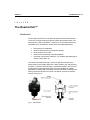
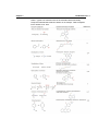
1
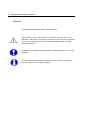
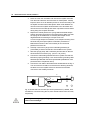
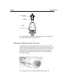
ReactorCell User manual Antec .... Proven Performance! 210.7014, Edition 2, 2011 Antec, Industrieweg 12, 2382 NV Zoeterwoude, The Netherlands T: +31 71 5813333, F: +31 71 5813334, E: [email protected], W: www.myantec.com Copyright ©2010 Antec Leyden. All rights reserved. Contents of this publication may not be reproduced in any form or by any means (including electronic storage and retrieval or translation into a foreign language) without prior agreement and written consent from the copyright of the owner. The information contained in this document is subject to change without notice. ROXY potentiostat, DECADE II, DECADE, INTRO, Sencell, Reactor cell, Reactor, ISAAC, HyREF, LINK, ADF, DECADE Dialogue, DECADE II Dialogue are trademarks of Antec Leyden BV. Whatman™ (word and device) and Whatman™ (word only) are trademarks of Whatman lnternational Ltd. SOLVENT IFD™ and AQUEOUS IFD™ are trademarks of Arbor Technologies, Inc. Clarity®, DataApex® are trademarks of DataApex Ltd. Microsoft® and Windows™ are trademarks of Microsoft Corporation. The information provided herein is believed to be reliable. Antec Leyden shall not be liable for errors contained herein or for incidental or consequential damages in connection with the furnishing, performance, or use of this manual. All use of the hardware or software shall be entirely at the user’s own risk. INTRODUCTION Table of contents WEEE directive All equipment of Antec Leyden which are subjected to the WEEE directive shipped after August 13, 2005 are compliant with the WEEE marking requirements. Such products are labelled with the “crossed out wheelie”, depicted on the left site. The symbol on the product indicates that the product must not be disposed as unsorted municipality waste. Collection & recycling information Please ship the part back to the manufacturer (Antec Leyden, the Netherlands) at the end-of-life time of the product. The manufacturer will take care of the proper disposal and recycling of the instrument at its facilities. Shipping address for the end-of-life products: Antec Leyden Industrieweg 12 2382NV Zoeterwoude The Netherlands In case of questions, or if further information is required about the collection & recycling procedure, please contact your local distributor. ROHS directive Our instruments are currently exempt from the RoHS directive because they fall under WEEE Annex IA categories 8 and 9, which includes medical devices and monitoring and control instruments. Nevertheless, we have taken steps to eliminate all restricted substances from our products. Intended use For research purposes only. While clinical applications may be shown, this instrument /part is not tested by the manufacturer to comply with the In Vitro Diagnostics Directive. Antec Leyden is an ISO 9001:2000 certified company. 1 2 ReactorCell user manual, edition 2 Symbols The following pictograms are used in this user manual: Warning/caution sign. It calls attention to a procedure or practice which, if not adhered to, could result in severe injury or damage to parts or all of the equipment. Do not proceed beyond a warning sign until the indicated conditions are fully understood and met. The attention sign signals relevant information. Read this information, as it might be helpful. The note sign signals additional information. It provides advice or a suggestion that may support you in using the equipment. INTRODUCTION Table of contents Safety practices Perform periodic leak checks on LC tubing and cell connections. Do not allow flammable and/or toxic solvents to accumulate. Follow a regulated, approved waste disposal program. Never dispose of such products through the municipal sewage system. LC equipments should be used by trained laboratory personnel only. Use proper eye and skin protection when working with solvents. Additional safety requirements or protection may be necessary depending on the chemicals used in combination with this equipment. Make sure that you understand the hazards associated with the chemicals used and take appropriate measures with regards to safety and protection. Use of this product outside the scope of this guide may present a hazard and can lead to personal injury. Spare parts and service availability Manufacturer provides operational spare parts of the instrument and current accessories for a period of five years after shipment of the final production run of the instrument. Spare parts will be available after this five years period on an ‘as available’ basis. Manufacturer provides a variety of services to support her customers after warranty expiration. Repair service can be provided on a time and material basis. Contact your local supplier for servicing. Technical support and training can be provided by qualified chemists on both contractual or as-needed basis. 3 4 ReactorCell user manual, edition 2 Table of contents I N T R O D U C T I O N WEEE directive 1 ROHS directive 1 Intended use 1 Symbols 2 Safety practices 3 Spare parts and service availability 3 Table of contents 4 The ReactorCell™ 5 Introduction 5 Three-electrode configuration 10 HyREF™ reference electrode 11 I/E curves 11 Example 12 Working electrodes 12 Installation 14 General precautions 14 Installation of the ReactorCell 14 Maintenance 17 HyREF 17 Working electrode maintenance 17 Decreased ReactorCell performance 18 Disassembly of the ReactorCell 18 Polishing 19 Assembly of the ReactorCell 20 TM Maintenance Magic Diamond electrode 21 Activation of the electrode using pulse mode 22 Activation of the electrode using scan mode in acidic conditions 24 Storage 26 Chapter 3 The ReactorCell™ 5 C H A P T E R 1 The ReactorCell™ Introduction The thin-layer ReactorCell™ has been developed for the electrochemical conversion of target compounds upfront a Mass Spectrometer (MS). The ReactorCell is a part of the ROXY™ systems for on-line Electrochemistry (EC)/MS and can be utilized for a wide variety of EC/MS applications: fast synthesis of metabolites rapid risk assessments of drug-protein binding signal enhancement in MS electrochemical cleavage of proteins/peptides mimicking natures redox reactions, e.g. oxidative stress/damage of proteins, DNA, lipids, etc The reactor cell is delivered with a set of four different electrode discs: Glassy Carbon (GC), Magic Diamond™ (MD), platinum (Pt), and gold (Au). A HyREF™ reference electrode (REF) is standard supplied. The use of an exchangeable working electrode offers maximum flexibility for multiple applications requiring different working electrode materials. Exchanging the working electrode only takes a minute. The Reactor cell has an effective volume of only 0.7 µL. Fig. 1. ReactorCell. 6 ReactorCell user manual, edition 2 Table 1 summarizes the reactions that can be simulated in the ReactorCell™ or µ-PrepCell™. The electrochemical oxidation reactions are among others: S-oxidation, N-dealkylation, hydroxylation and dehydrogenation. For successful and efficient conversion, the parameters as the potential, mobile phase composition (organic solvent concentration, pH), and flow rate need to be optimized depending on the type of the analyzed compound. In general, the samples can be oxidized in the solutions containing supporting electrolyte at concentrations of 10mM or higher. The higher concentration of supporting electrolyte, ca. 100mM, can improve conversion, but from the other hand it can also affect the ESI response (ionization suppression). An additional concern focuses on whether the mobile phase is compatible with ESI MS and to fulfill this requirement ammonium acetate, ammonium formate, formic acid or acetic acid can be used (It is not recommended to use acetic acid and its derivatives with Magic Diamond electrode). pH should be considered when optimizing the mobile phase composition. Although, in the most cases pH is adjusted to 7.4 (physiological value) with ammonium hydroxide, the oxidation reactions are pH dependent. E.g., N-oxidation can occur only under basic conditions but some desalkylation reactions happen only in the acidic medium. An optimization of the mobile phase composition requires the addition of an organic solvent. Acetonitrile or methanol can be added depending on the solubility of the sample. Furthermore, the higher % of acetonitrile can diminish the adsorption of the most hydrophobic compounds. For the samples that are difficult to soluble in the aqueous buffer the non-aqueous solution as 0.1M tetrabutylammonium perchlorate (TBAP) dissolved in ACN/H2O 99/1 (v/v) can be used. The examples of the mobile phases in relation to the specific compound are presented in the Table 2. The flow rate is another factor that can influence the conversion rate. In general lowering the flow rate will increase the conversion efficiency. The recommended flow rate for µ-PrepCell™ is 20-50µL/min, for ReactorCell™ the optimal flow rate is in the range of 5-20µL/min. The driving force of the electrochemical reaction is potential applied between the working and counter electrodes. The ROXY™ Potentiostat allows using cell potentials in the range from -4.9V to +4.9V. To optimize the potential it is recommended to run the MS Voltammogram (ramp the potential within specified range) and estimate the optimum value for the desired metabolite formation. Furthermore, the MS Voltammogram is the fingerprint of the compound itself and provides the information about oxidative processes occurring in the cell. In the ROXY™ potentiostat the DC and Scan mode are available for efficient metabolite synthesis. The DC mode is based on applying a static (single) potential during the whole conversion process. Note that the synthesis of different metabolites of one compound may require operation at different potential settings. In the Scan mode stabile oxidation conditions are obtained by continuous scanning between two preset potentials values (E1 and E2) with a certain scan rate (unit: mV/s). Chapter 3 The ReactorCell™ 7 Table 1.Typical CYP reactions that can be simulated electrochemically. Compound indicated with asterisk is drawn as an example. Table is adapted from Lohmann et al. 2010. 8 ReactorCell user manual, edition 2 Table 2. Examples of mobile phases used for electrochemical oxidation. Compound Mobile phase Electrode Acetaminophen 20mM ammonium acetate in 25% methanol Amodiaquine (1) Glassy Carbon, Magic 20mM ammonium formate (pH 7.4 adjusted with ammonium hydroxide) in Diamond 50% acetonitrile 50% methanol Glassy Carbon and 50% 10 mM aqueous formic acid Amodiaquine (2) Irinotecan Angiotensin Adenosine Tetrazepam Lidocaine Toremifene LYL, LWL (peptides) Glassy Carbon, Magic Diamond 20mM ammonium formate with 0.1% Glassy Carbon, Magic formic acid (pH 3.3) in 50% acetonitrile Diamond (on both different oxidation profiles were obtained) 0.1% formic acid in 50% acetonitrile Magic Diamond 20mM ammonium formate (pH 7.3 adjusted with ammonium hydroxide) in 50% acetonitrile 10mM formic acid (pH 3.1) Magic Diamond Platinum Gold 0.1 M TBAP dissolved in ACN or ACN/H2O 99/1 (v/v) Glassy Carbon 20mM ammonium formate (pH 7.4 adjusted with ammonium hydroxide) in 50% methanol 90/10/1 (v/v/v) water/acetonitrile/formic Glassy Carbon acid The information how to acquire the MS Voltammogram and use the Scan or DC mode for metabolite synthesis are described in the ROXY Potentiostat User manual (210.7010) and Dialogue for ROXY user guide (210.7017). References: 1. A. Baumann et al., J. Chromatogr. A, 121 6, 3192–3198 (2009). 2. T. Johansson, L. Weidolf and U. Jurva, Rapid Commun. Mass Spectrom., 21, 2323–2331 (2007). 3. S.M. van Leeuwen et al., Anal. Bioanal. Chem., 382, 742–750 (2005). 4. W. Lohmann and U. Karst, Anal. Chem., 79, 6831–6839 (2007). 5. K.G. Madsen et al., Chem. Res. Toxicol., 21, 1107–1119 (2008). 6. S.M. van Leeuwen, H. Hayen and U. Karst, Anal. Bioanal. Chem., 378, 917–925 (2004). 7. B. Blankert et al., Electroanalysis, 17, 1501–1510 (2005). 8. W. Lohmann et al., Anal. Bioanal. Chem., 386, 1701–1708 (2006). Chapter 3 The ReactorCell™ 9 Note that for use of a Magic DiamondTM electrode a ROXY potentiostat DCC or QCC (p/n 210.0050 or 210.0060, respectively). with an extended Ec range (-5 / +5 V) is required. Please contact you local supplier for additional information or advice. The construction of the ReactorCell is such that both fluid connections can be used as in- or outlet. 10 ReactorCell user manual, edition 2 Three-electrode configuration In the Reactor cell a three-electrode configuration is used (Fig. 2). The working potential is set between the working electrode and the auxiliary electrode (AUX). The auxiliary electrode is kept at a precisely defined reference electrode potential by means of the so-called voltage clamp. This is an electronic feedback circuit that compensates for polarisation effects at the electrodes. At the working electrode, which is kept at virtual ground, the electrochemical reaction takes place, i.e. electrons are transferred at the working electrode. This results in an electrical current to the I/E converter, which is a special type of operational amplifier. The output voltage can be measured by an integrator or recorder. Fig. 2. Schematic representation of an electrochemical cell with a threeelectrode configuration. Essentially, for the oxidation or reduction reaction it would be sufficient to use only two electrodes. However, the three-electrode configuration has several advantages over a two-electrode configuration. If the working potential would be applied only over an auxiliary electrode versus the working electrode (without reference electrode), the working potential would continuously change due to polarisation effects at the electrodes, resulting in highly unstable working conditions. If the working potential would be applied only over the reference electrode versus the working electrode (without auxiliary electrode), the working Chapter 3 The ReactorCell™ 11 potential would be very well defined. However, the potential of a reference electrode is only well defined if the current drawn is extremely low (picoamperes) resulting in a very limited dynamic range. A three-electrode configuration combines the best of both configurations. The reference electrode stabilises the working potential and the auxiliary electrode can supply high currents. This results in the tremendous dynamic range of a three-electrode system. HyREF™ reference electrode The Reactor cell is standard equipped with a maintenance free HyREF. The HyREF is fully comparable with the standard Ag/AgCl REF as to baseline stability and S/N ratio. An important characteristic of the HyREF is the pH dependence of the reference potential. It is important to realise that if the pH of the mobile phase is changed, also the optimum working potential changes. In such case it is advisable to construct a hydrodynamic or scanning voltammogram. I/E curves The reference potential of an Ag/AgCl or HyREF are different (Fig. 3). pH 3.3 6.2 7.5 11.8 400 E (V) 300 E (V) 232 130 90 0 200 100 0 0 5 10 15 pH Fig. 3. Potential difference between HyREF and Ag/AgCl REF versus pH. 12 ReactorCell user manual, edition 2 So, if an Ag/AgCl REF is replaced by a HyREF, the pH effect on HyREF, compared to Ag/AgCl must be taken into account. The pH-voltage relation is described by: EHyREF = EAg/AgCl - 328 + 29.9 pH (1) Example If an Ag/AgCl REF is exchanged for a HyREF a working potential of 800 mV (vs. Ag/AgCl) at pH 3, has to be changed to: EHyREF = 800 - 328 + 29.9*3 = 560 mV (vs. HyREF) As a rule of thumb, the working potential should be chosen such that a similar background signal (I-cell) is measured with the HyREF as in using the Ag/AgCl REF. Working electrodes Electrochemical conversion puts high demands on the working electrode material. The working electrode should be made of a (electro-)chemically inert material. Furthermore, to avoid an irregular flow profile over the electrode, it should have a very well defined surface. In the Table 3 the working potential limits are listed of the WE materials available for ReactorCell. The values presented in the table are only the estimation and will depend on mobile phase composition (pH, supporting electrolyte) and the analyzed compound itself. At high positive working potentials the water in the mobile phase electrolyses and results in decrease in metabolites formation. In case of electrolysis of the water/mobile phase the cell current (Icell) readout will display the message “overload” and auxiliary potential (Eaux) will have the extreme value (-9.9V) (With the default range value of 200 µA). Furthermore, the electrospray signal will become very unstable because of gas formed in the cell and loss of the signal can be observed. When such a phenomenon is observed it is recommended to adjust the potential to a lower value. Formation of metal oxides, resulting in an increase in background current is a limiting factor for metal electrodes. For negative potentials the use of platinum electrodes is strongly limited by the ease of reducing hydrogen ions to hydrogen gas. Chapter 3 The ReactorCell™ 13 Table 3. Working potential limits for electrodes (WE) used with µ-PrepCell. WE material Glassy carbon Magic diamond Gold Platinum potential limits vs. HyREF (V) Oxidation Reduction +2.5V +3.5V +2.0V +2.0V -1.5V -2.5V -2.0V -2.0V Magic DiamondTM is a new working electrode material available for the ReactorCell. The MD electrode consisting of an ultra-thin film of doped diamond material deposited on a Si wafer. The special properties of doped diamond electrodes, such as a large potential window, their inertness and excellent response stability, makes them well suited for a wide variety electro-analytical application aa well as for ROXY EC system. 14 ReactorCell user manual, edition 2 C H A P T E R 2 Installation General precautions 1. Always make sure that the surfaces of the spacer and working electrode are dry and free from particulate matter before assembling the cell. Clean fingerprints from spacer and electrode surfaces with acetone or methanol. 2. If the auxiliary electrode needs to be cleaned, wipe the surface careful with a soft tissue soaked in acetone or methanol. Do not apply force you may damage the electrode surface. 3. Make sure that the working electrode has a mirror-like appearance before re-assembling the ReactorCell. The Magic Diamond electrode is an exception. This particular WE electrode has a crystalline blue/gray surface structure. This electrode must not be polished mechanically. Polishing the MD electrode surface will damage the electrode and lead to loss of performance. Follow the specific maintenance instructions in chapter 3. 4. If the ReactorCell is not in use and removed out of the LC system, we recommend that you disassemble the cell and clean all surfaces (turn off the cell first). Installation of the ReactorCell The ReactorCell is assembled properly when it arrives. Make sure that all marked items on the checklist are included. Never switch on the ReactorCell if: the (black, red and blue) cell cable is not correctly connected, the cell is only partly (or not at all) filled with mobile phase containing the supporting electrolyte (e.g., ammonium formate, ammonium acetate, formic acid), because damage to the working electrode or the electronics may occur. Use proper eye and skin protection when working with solvents. Chapter 3 Installation 15 To install the µ-PrepCell in your ROXY EC system follow the steps below: Fig. 4. Schematic drawing of the ReactorCell in a ROXY EC system. Top part: Phase I configuration, bottom part: Phase II configuration. 1. Have some tissues ready and wear protective gloves as you probably will spill some mobile phase during the mounting procedure. 2. Connect the syringe filled with mobile phase to the inlet of the ReactorCell using tubing assembly Q’’ (p/n 180.0230A) and tighten it carefully. Make sure that the syringe and tubing is air-bubble free when connecting it to the cell. The mobile phase should contain the supporting electrolyte (e.g., ammonium formate, ammonium acetate, formic acid) to provide proper working conditions and to prevent the damage of the working electrode or the electronics. 3. Connect tubing assembly H’’ (p/n 180.0219) to the outlet of the cell but not yet to the MS. Flush ReactorCell with the mobile phase and ensure that all air bubbles are removed. Keep it under an angle of 45 degree to clear out the air in the cell. During clearing tick against the cell to promote removal of air bubbles. 16 ReactorCell user manual, edition 2 4. Place the cell in the cell holder and unscrew the HyREF electrode from the AUX inlet block at low flow rate of mobile phase. Visually inspect if there are no air bubbles present. It can be necessary to fill the HyREF chamber with mobile phase. When all air bubbles are removed mount the HyREF electrode back in the AUX block and remove the excess mobile phase which is pushed out the chamber during fixing of the HyREF electrode. 5. Replace the mobile phase in the syringe with the desired sample solution and place the syringe in the syringe pump. Make sure that the syringe is air bubble free. If necessary the sample can be degassed before introducing the sample to the cell. In case of high sample concentration, more frequent cleaning of the electrode may be required (See the activation procedures in Maintenance section of this User manual) to recover the full performance of the cell. 6. Carefully connect the syringe to the inlet tubing assembly Q’’ (180.0230A), avoid the introduction of air bubbles in the system. 7. Start the syringe pump with a sufficiently low flow rate for efficient electrochemical conversion (e.g. 1µL/min - 20 µL/min). 8. Connect the outlet tubing with the MS source (make sure that the MS inlet is proper grounded). If not use the ROXY grounding cable 250.0035 provided with the ROXY potentiostat (available for units purchased after 1 September 2010). 9. Connect the cell cable to the ReactorCell as illustrated in the Fig. 5. The red connector should be connected to the Working electrode, the black one to the HyREF reference electrode and the blue connector to the Auxiliary electrode. red LC out AUX blue WORK REF black LC in Fig. 5. ReactorCell and cell cable (for ROXY potentiostat™). WORK, AUX and REF are connected using the red, blue and black lead of the cell cable, respectively. Use only our factory-supplied fingertights in the flow cell, others may cause serious damage! Chapter 3 Maintenance 17 C H A P T E R 3 Maintenance HyREF The HyREF reference electrode is in principle maintenance free. If not in use they should be stored dry after disassembling the flow cell. Working electrode maintenance Cleaning of the working electrode is necessary if the electrode surface has been electrochemically changed. This may be due to fouling by oxidation (reduction) reaction products. Excessively high currents also may change the electrode surface. This is noticed by a strongly decreased sensitivity after prolonged use. Hy-REF reference electrode auxiliary electrode inlet block retaining ring 50 µm spacer working electrode disk Working electrode assembly electrode swivel nut Fig. 6. Exploded diagram of ReactorCell. 18 ReactorCell user manual, edition 2 Decreased ReactorCell performance Several actions can be taken at decreased flow cell performance. Avoid unnecessary polishing, take the next step only if the previous was not successful. 1. Wiping the electrode surface with a tissue wetted with methanol or acetone 2. Polishing the electrode surface. Only apply polishing on Metal and GC electrode only. Do not polish Magic Diamond electrodes, for Diamond electrodes follow the (re)activation procedure described in a separate section of this manual. Disassembly of the ReactorCell If the working electrode needs maintenance, the cell has to be disassembled (see Fig. 6). Before disassembling the flow cell read General precautions. 1. Switch off the flow cell and HPLC pump and disconnect both fingertights. 2. Unscrew the electrode swivel nut and take out the working electrode assembly. 3. Remove the retaining ring. 4. Take out the WE contact (Fig. 7). 5. Clean and dry the spacer. 6. Clean or polish the WE as described below. 7. Note that the WE has only 1 side with a mirror-like surface. This side is facing the LC liquid and should be polished. Fig. 7. Electrode assembly. The working electrode is fitted on the electrode shaft with electrode retaining ring (1) and held in place by a silicon holder (2). Use proper eye and skin protection when working with solvents. Chapter 3 Maintenance 19 Polishing The polishing procedure is for metal & GC working electrodes only. Do not polish the thin-film Magic Diamond electrodes, it will lead to damage of the electrode surface and a loss of performance. For Magic Diamond electrodes follow the activation procedure described in a separate section of this manual. 1. Shake diamond slurry thoroughly before use!! 2. Rinse the polishing disc with demi water before applying the diamond slurry! 3. Apply a small amount of slurry on the wetted polishing disc, usually one drop is sufficient. 4. Put the working electrode with the face down on the disc and polish the electrode with a ‘figure 8’ motion for about one minute. Apply only gentle pressure with one finger. 5. Clean the electrode with an ethanol-wetted tissue and check the surface visually; repeat the procedure if necessary. 6. Reassemble the cell. 7. Clean the polishing disc with demi water. 8. Store the polishing disc dust free in its plastic bag. There is a dedicated flattening and polishing kit for metal WE available (p/n 250.1045). This is a tailor-made kit to flatten and polish a metal Working Electrode (WE) disc of a Reactor cell. It consists of a three stage flattening-polishing procedure. Steps: [1] [2] [3] Flattening step, coarse (30 um flattening plate) Flattening step, fine (12 um flattening plate) Polishing step, fine (polishing disk with diamond slurry) The procedure enables the user to restore the flat metal WE surface again in a reproducible way. 20 ReactorCell user manual, edition 2 Assembly of the ReactorCell 1. Make sure that the surface of the spacer and inlet block is dry and free from particulate matter. Clean fingerprints from spacer with acetone or methanol. Always assemble the two halves of the cell body first, prior to fitting the working electrode assembly. To prevent the spacer from moving keep the ReactorCell with the inlet block down as illustrated in Fig. 7. 2. Take the working electrode disk and press it in its silicone holder 3. Make sure that the surface of the working electrode is dry and free from particulate matter. Clean fingerprints from electrode surface with acetone or methanol. 4. Put the spacer in position and install the retaining ring. 5. Install the working electrode assembly. 6. Close the outlet tubing (by finger) and force the mobile phase in the reference electrode reservoir. 7. Install the reference electrode without including bubbles. 8. Place the cell with the outlet on top to prevent entrapment of bubbles. Connect the cell cable as illustrated in Fig. 5. 9. Carefully tighten the fingertights. Overtightening will damage the inlet block. The surface of the inlet block, working electrode and spacer should be dry when assembling the ReactorCell. Chapter 3 Maintenance 21 Working electrode assembly electrode swivel nut retaining ring 50 µm spacer Fig. 8. Assembling the ReactorCell: first fit the spacer and the retaining ring, then WE assembly and the electrode swivel nut. TM Maintenance Magic Diamond electrode The Magic Diamond working electrode (see Fig. 9) consists of an ultra-thin crystalline Diamond layer deposited on top of a Si substrate. Therefore, such electrode cannot be polished to restore the electrode surface in case of loss of sensitivity due to fouling. An effective method to restore the detection performance is by electrochemically reactivation of the electrode surface under acidic conditions. Fig. 9. Working electrode assembly with Magic Diamond electrode . 22 ReactorCell user manual, edition 2 Activation of the electrode using pulse mode This activation procedure can be suitable for both MD and GC electrodes. 1. Refill the syringe with the mobile phase containing the supporting electrolyte, e.g., the same mobile phase used for oxidation of the sample and start the flow rate (10-20µL/min). 2. Go to the Options pull down menu and choose “Detection mode” (Fig. 10). Fig. 10. Pull down menu: Options Detection Mode. 3. Select Pulse mode (Fig. 11) and click OK. Fig. 11. Select mode window. Set the parameters in the cell control window (Fig. 12). It is recommended to set the Output Range to 200 µA). Parameter E1 E2 E3 t1 t2 t3 ts Value +2V -2V 0V 1000 ms 1000 ms 0 ms 20 ms Chapter 3 Maintenance 23 Fig. 12. The cell settings in the pulse mode for MD electrode activation. 4. Set Run time value to 5 min and turn on the cell. 5. Go to Options pull down menu and click Start Run (Fig. 20). Program will ask to save the data (The excel file will be created). And start the acquisition. Fig. 13. Start the activation procedure. After the activation procedure turn OFF the cell and leave the flow for additional 1-2min. The activation procedure is available also as a program (Activation_pulse_rev01.evt) and can be executed automatically via events window (Fig. 21). The method can be found in My Documents and in the subfolders: Dialogue\Templates. 24 ReactorCell user manual, edition 2 For the newest version of the Dialogue software check: www.myantec.com The detailed background information about the supplied events files and relevant Dialogue settings are provided in the Dialogue for ROXY User guide (210.7017). Fig. 14. Activation procedure event table. In case that no significant improvement of the cell performance is seen: A. For MD electrode use the additional procedure described in the next paragraph (Activation of the electrode using scan mode in acidic conditions). B. For GC electrode you can polish the electrode manually as described in the previous chapter (Polishing of the GC electrode). Activation of the electrode using scan mode in acidic conditions This activation procedure is suitable only for MD electrode. 1. Disassemble the Reactor cell as described on page 21. Keep the MD electrode disc fixed inside the working electrode assembly. 2. Wipe the electrode surface with a tissue wetted with methanol or acetone and subsequently with demi water to clean the electrode surface. Under all circumstances try to avoid direct contact of Chapter 3 Maintenance 25 the electrode surface with fingers. The skin contains fatty substances which will foul the electrode. 3. Assemble the ReactorCell as described in the previous section. 4. Prepare a mobile phase of 0.5 M Nitric acid (HNO3), install the ReactorCell and prime it with mobile phase to remove any air bubbles. 5. Set the flow rate of 10 µL/min (Ensure that syringe volume is enough to generate the flow for at least 1 h). Make sure that all parts that are not acid-resistant such as: nylon inlet filters, column are not connected in the system during this step. 6. Set the ROXY POTENTIOSTAT in SCAN mode with the following settings: E1 = -3.00 Volt, E2 = +3 Volt, Scan rate: 50 mV/s, scan cycle: continuous and range 200 µA/V. 7. Start scanning under acidic conditions for 1 hours. 8. After scanning switch off the cell and the flow rate, replace the mobile phase by HPLC grade water and flush the cell to remove the acidic solution. 9. You can start up measurements again. In the case there is no significant sensitivity improvement observed, repeat step 1 to 10 and increase the total scan time (step 7). One can also try to perform the activation procedure under the mobile phase conditions of the application. Furthermore, in literature anodic treatments are reported (for example the application of a static potential of + 3 Volt vs. Ag/AgCl for 5 – 10 minutes) to restore the electrode response. Such procedure could be executed as an alternative, if the above-mentioned procedure does not lead to satisfactory results. Electrochemical reactivation procedure for MD electrode is part of the ROXY potentiostat firmware and available via display panel (DiagActivate). The scan settings and the duration are as described in points 6 and 7, and only “push button” action is needed to execute it (See ROXY Potentiostat user manual (210.7010)). Replace the Magic Diamond electrode disc when no improvement is seen after repeated reactivation/conditioning attempts. 26 ReactorCell user manual, edition 2 Chemical compatibility: The MD electrode exhibit an excellent inertness and can be used with a large variety of mobile phase and chemicals. However it has been observed that the MD electrode operational lifetime is strongly reduced when exposed to fluorinated acids, such as tri-fluoroacetic acid. Even at relatively low concentrations (2% in aqueous solution) significant damage of the diamond electrode was seen within days of operation. Storage If the ReactorCell is not in use and uncoupled from the LC system, we recommend that you disassemble the cell and clean and dry all surfaces. Before removing the cell from the detector, turn off the cell first.