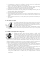
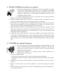
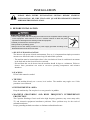
1
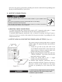
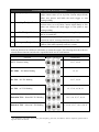
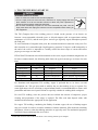
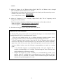
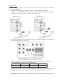
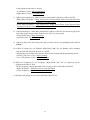
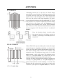
LOTOS LTPAC2500 5 IN 1 CUT/MMA/AC TIG/DC TIG/PULSE TIG 1 TABLE OF CONTENTS SAFETY...…………………………………………………………………………3 SPECIFICATIONS…….…………………………………………………………7 What’s Included………………………………………………………………..7 Power Supply Rating…..……………………………………………………....8 INSTALLATION…………………………………………………………………9 Before Installation……………………………………………………………9 Input Connection……………………………………………………………11 Output Connection…………………………………………………………..12 OPERATION...………………………………………………………………….15 Before Operation……………………………………………………………15 Operation……………………………………………………………………20 CUT (Plasma Cutting) Start Up……….……………………………………20 MMA (MMA Welding) Start Up……………………………………………21 TIG (TIG Welding) Start Up…………………..……………………………23 MAINTENANCE………………………………………………………………31 TROUBLESHOOTING………………………………………………………32 OTHER ACCESSORIES………………………………………………………35 APPENDIX………………………………..………………………………36 2 SAFETY PLEASE READ AND UNDERSTAND THE FOLLOWING SAFETY HIGHLIGHTS. BE SURE THAT ALL INSTALLATION, OPERATION, MAINTENANCE AND REPAIR PROCEDURES ARE PERFORMED ONLY BY QUALIFIED INDIVIDUALS. ARC AND TIG WELDING CAN BE HAZARDOUS. PROTECT YOURSELF AND OTHERS FROM POSSIBLE SERIOUS INJURY OR DEATH. KEEP CHILDREN AWAY. PACEMAKER WEARERS SHOULD CONSULT WITH THEIR DOCTOR BEFORE OPERATING. ELECTRIC AND MAGNETIC FIELDS may be dangerous Electric current flowing through any conductor causes localized Electric and Magnetic Fields (EMF). Welding current creates EMF fields around welding cables and welding machines. EMF fields may interfere with some pacemakers, and welders having a pacemaker should consult their physician before welding. Exposure to EMF fields in welding may have other health effects which are now not known. All welders should use the following procedures in order to minimize exposure to EMF fields from the welding circuit: Route the electrode and work cables together - Secure them with tape when possible. Never coil the electrode lead around your body. Do not place your body between the electrode and work cables. If the electrode cable is on your right side, the work cable should also be on your right side. Connect the work cable to the work piece as close as possible to the area being welded. Do not work next to welding power source. ELECTRIC SHOCK can be fatal The electrode and work (or ground) circuits are electrically “hot” when the welder is on. Do not touch these “hot” parts with your bare skin or wet clothing. Wear dry, hole-free gloves to insulate hands. Insulate yourself from work and ground using dry insulation. Make certain the insulation is large enough to cover your full area of physical contact with work and ground. In addition to the normal safety precautions, if welding must be performed under electrically hazardous conditions (in damp locations or while wearing wet clothing; on metal structures such as floors, gratings or scaffolds; when in cramped positions such as sitting, kneeling or lying, if there is a high risk of unavoidable or accidental contact with the work piece or ground) use the following equipment: Semiautomatic DC Constant Voltage (Wire) Welder. DC Manual (MMA) Welder. AC Welder with Reduced Voltage Control. 3 In semiautomatic or automatic wire welding, the electrode, electrode reel, welding head, nozzle or semiautomatic welding gun are also electrically “hot”. Always be sure the work cable makes a good electrical connection with the metal being welded. The connection should be as close as possible to the area being welded. Ground the work or metal to be welded to a good electrical (earth) ground. Maintain the electrode holder, work clamp, welding cable and welding machine in good, safe operating condition. Replace damaged insulation. Never dip the electrode in water for cooling. Never simultaneously touch electrically “hot” parts of electrode holders connected to two welders because voltage between the two can be the total of the open circuit voltage of both welders. When working above floor level, use a safety belt to protect yourself from a fall should you get a shock. ARC RAYS can burn Use a shield with the proper filter and cover plates to protect your eyes from sparks and the rays of the arc when welding or observing open arc welding. Use suitable clothing made from durable flame-resistant material to protect your skin and that of your helpers from the arc rays. Protect other nearby personnel with suitable, non-flammable screening and/or warn them not to watch the arc nor expose themselves to the arc rays or to hot spatter or metal. FUMES AND GASES can be dangerous Welding may produce fumes and gases hazardous to health. Avoid breathing these fumes and gases. When welding, keep your head out of the fume. Use enough ventilation and/or exhaust at the arc to keep fumes and gases away from the breathing zone. When welding with electrodes which require special ventilation such as stainless or hard facing or on lead or cadmium plated steel and other metals or coatings which produce highly toxic fumes, keep exposure as low as possible and below Threshold Limit Values (TLV) using local exhaust or mechanical ventilation. In confined spaces or in some circumstances, outdoors, a respirator may be required. Additional precautions are also required when welding on galvanized steel. Do not weld in locations near chlorinated hydrocarbon vapors coming from degreasing, cleaning or spraying operations. The heat and rays of the arc can react with solvent vapors to form phosgene, a highly toxic gas, and other irritating products. Shielding gases used for arc welding can displace air and cause injury or death. Always use enough ventilation, especially in confined areas, to insure breathing air is safe. Read and understand the manufacturer’s instructions for this equipment and the consumables to be used, including the material safety data sheet (MSDS) and follow your employer’s safety practices. MSDS forms are available from your welding distributor or from the manufacturer. 4 WELDING SPARKS can cause fire or explosion Remove fire hazards from the welding area. If this is not possible, cover them to prevent the welding sparks from starting a fire. Remember that welding sparks and hot materials from welding can easily go through small cracks and openings to adjacent areas. Avoid welding near hydraulic lines. Have a fire extinguisher readily available. Where compressed gases are to be used at the job site, special precautions should be used to prevent hazardous situations. When not welding, make certain no part of the electrode circuit is touching the work or ground. Accidental contact can cause overheating and create a fire hazard. Do not heat, cut or weld tanks, drums or containers until the proper steps have been taken to insure that such procedures will not cause flammable or toxic vapors from substances inside. They can cause an explosion even though they have been “cleaned”. Sparks and spatter are thrown from the welding arc. Wear oil free protective garments such as leather gloves, heavy shirt, cuff-less trousers, high shoes and a cap over your hair. Wear ear plugs when welding out of position or in confined places. Always wear safety glasses with side shields when in a welding area. Connect the work cable to the work as close to the welding area as practical. Work cables connected to the building framework or other locations away from the welding area increase the possibility of the welding current passing through lifting chains, crane cables or other alternate circuits. This can create fire hazards or overheat lifting chains or cables until they fail. CYLINDER may explode if damaged Use only compressed gas cylinders containing the correct shielding gas for the process used and properly operating regulators designed for the gas and pressure used. All hoses, fittings, etc. should be suitable for the application and maintained in good condition. Always keep cylinders in an upright position securely chained to an undercarriage or fixed support. Cylinders should be located: Away from areas where they may be struck or subjected to physical damage. A safe distance from arc welding or cutting operations and any other source of heat, sparks, or flame. Never allow the electrode, electrode holder or any other electrically “hot” parts to touch a cylinder. Keep your head and face away from the cylinder valve outlet when opening the cylinder valve. Valve protection caps should always be in place and hand tight except when the cylinder is in use or connected for use. 5 ELECTRICALLY POWERED EQUIPMENT can be dangerous Turn off input power using the disconnect switch at the fuse box before working on the equipment. Install equipment in accordance with the local codes and the manufacturer’s recommendations. Ground the equipment in accordance with the manufacturer’s recommendations. MOVING PARTS can cause injury Keep away from moving parts such as fans. Keep all doors, panels, covers, and guards closed and securely in place. 6 SPECIFICATIONS WHAT’S INCLUDED Power Supply Plasma Cutting Torch TIG Welding Torch MMA Electrode Holder Ground Clamp TIG Torch Accessories Foot Pedal Air Filter & Regulator Air Hose Air Hose Connections 7 POWER SUPPLY RATINGS LTPAC2500 Input Voltage Power Efficiency General Specification AC 220~240V±10%, 1-PH, 50/60Hz ≥80% 20.5” (530mm) L 8.7” (220mm) W 15.8” (400mm) H 73lbs (33kg) 60% 8.2’ (2.5m) Dimensions Weight Duty Cycle Power Cable Output Current Open Circuit Voltage Gas Supply Plasma Cutting Specification 10~40A 235V Clean, dry, oil-free air 0.25~0.3Mpa @15A 0.3~0.35Mpa @20A 0.35~0.4Mpa @30A 0.4~0.45Mpa @40A 5~10s High Frequency 0.5” (12.7mm) Recommended Pressure Recommended Post-flow Pilot Arc Start Mode Maximum Cutting Thickness AC TIG: 20~250A DC TIG: 10~250A 60~80V 50~70Hz Square Waves 30% ~ 70% Electrode Positive Clean, dry, oil-free argon or helium gas 14L/min @50~100A 20L/min @150~200A 25L/min @250A 0.3” (8mm) Output Current TIG Welding Specification Open Circuit Voltage AC TIG - Output Frequency AC TIG - AC Balance Gas Supply Recommended Gas Flow Rate Maximum Welding Thickness MMA Welding Specification Output Current Open Circuit Voltage ARC Force Pulse Mode Pulse Current Pulse Duty Pulse Frequency Base Current 20~200A 60~80V 0~50A 10~250A 10%~90% 0.5~200Hz 10~90% 8 INSTALLATION PLEASE READ ENTIRE INSTALLATION SECTION BEFORE STARTING INSTALLATION. BE SURE THAT ONLY QUALIFIED PERSONNEL SHOULD PERFORM THIS INSTALLATION. BEFORE INSTALLATION ELECTRIC SHOCK can kill Turn the input power OFF and unplug the machine from the receptacle before working on this equipment. Allow machine to sit for 5 minutes minimum to allow the power capacitors to discharge before working inside this equipment. Insulate yourself from the work and ground. Always wear dry insulating gloves. Always connect the welding machine to a power supply grounded according to the National Electrical Code and local codes. SELECT SUITABLE LOCATION The Inverter will operate in harsh environments. Even so, it is important that simple preventative measures are followed in order to assure long life and reliable operation. The machine must be located where there is free circulation of clean air such that air movement in the back and out the front will not be restricted. Dirt and dust that can be drawn into the machine should be kept to a minimum. Failure to observe these precautions can result in excessive operating temperatures and nuisance shutdown. STACKING LTPAC2500 cannot be stacked. TILTING Place the machine directly on a secure, level surface. The machine may topple over if this procedure is not followed. ENVIRONMENTAL AREA Keep the machine dry. Do not place it on wet ground or in puddles. MACHINE GROUNDING AND HIGH FREQUENCY INTERFERENCE PROTECTION The Capacitor Discharge Circuit used in the high frequency generator, may cause many radio, TV and electronic equipment interference problems. These problems may be the result of radiated interference. Proper grounding methods can reduce or eliminate radiated interference. 9 Radiated interference can develop in the following four ways: 1. Direct interference radiated from the welder. 2. Direct interference radiated from the welding leads. 3. Direct interference radiated from feedback into the power lines. 4. Interference from re-radiation of “pickup” by ungrounded metallic objects. Keeping these contributing factors in mind, installing equipment per the following instructions should minimize problems. Keep the welder power supply lines as short as possible and enclose as much of them as possible in rigid metallic conduit or equivalent shielding for a distance of 50 feet (15.2m). There should be good electrical contact between this conduit and the welder case ground. Both ends of the conduit should be connected to a driven ground and the entire length should be continuous. Keep the work and electrode leads as short as possible and as close together as possible. Lengths should not exceed 25 ft (7.6m). Tape the electrode and work leads together into one bundle when practical. Be sure the torch and work cable rubber coverings are free of cuts and cracks that allow high frequency leakage. Keep the torch in good repair and all connections tight to reduce high frequency leakage. The work terminal must be connected to a ground within ten feet of the welder, using one of the following methods. a) A metal underground water pipe in direct contact with the earth for ten feet or more. b) A 3/4” (19mm) galvanized pipe or a 5/8” (16mm) solid galvanized iron, steel or copper rod driven at least eight feet into the ground. The ground should be securely made and the grounding cable should be as short as possible using cable of the same size as the work cable, or larger. Grounding to the building frame electrical conduit or a long pipe system can result in re-radiation, effectively making these members radiating antennas. Keep all panels securely in place. All electrical conductors within 50ft (15.2m) of the welder should be enclosed in grounded, rigid metallic conduit or equivalent shielding. Flexible metallic conduit is generally not suitable. When the welder is enclosed in a metal building, several earth driven electrical grounds connected (as in 5b above) around the periphery of the building are recommended. Failure to observe these recommended installation procedures can cause radio or TV interference problems. 10 INPUT CONNECTIONS ELECTRIC SHOCK can be fatal Have a qualified electrician install and service this equipment. Turn the input power OFF and unplug the machine from the receptacle before working on this equipment. Allow machine to sit for 5 minutes minimum to allow the power capacitors to discharge before working inside this equipment. Do not touch electrically hot parts. Machine must be plugged into a receptacle that is grounded according to the National Electrical Code and local codes. Do not remove or defeat the purpose of the power cord ground pin. Be sure the voltage, phase, and frequency of the input power is as specified on the rating plate, located on the backboard of the machine. CONNECTION PROCEDURE The Inverter LTPAC2500 must be connected to AC220V±10%, 230V±10%, 240V±10%, 50/60Hz Single phase supply. 1 Fuse the input circuit with time delay fuses or delay type circuit breakers. Using fuses or circuit breakers smaller than recommended may result in “nuisance” shut-offs from welder inrush currents even if not welding at high currents. The Inverter LTPAC2500 are recommended for use on an individual branch circuit. 220V INPUT (Figure A.0) The equipment is provided with a 220V cable, 8.2ft. (2.5m) in length. The rated output of the LTPAC2500 is available when connected to a 40A branch circuit. When connected to a branch circuit with lower amp rating, lower welding current and duty cycle must be used. An output guide is provided on the right. The values are approximate and must be adjusted downward if the fuse or circuit breaker trips off. Other loads on the circuit and fuse/circuit breaker characteristics will affect the available output. Please do not exceed the welding conditions indicated in Table 1. Output Guide Under Lower Amp Rating 15A branch circuit 20A branch circuit 10% duty cycle MMA: 75A TIG: 105A CUT: 20A 10% duty cycle MMA: 90A TIG: 130A CUT: 25A Table 1 Failure to wire as instructed may cause personal injury or damage to equipment. To be installed or checked by an electrician or qualified person only. Also called “inverse time” or “thermal/magnetic” circuit breakers. These circuit breakers have a delay in tripping action that decreases as the magnitude of the current increases. 1 11 In all cases, the green or green/yellow grounding wire must be connected to the grounding pin of the plug, usually identified by a green screw. OUTPUT CONNECTIONS ELECTRIC SHOCK can be fatal Keep the electrode holder, TIG torch and cable insulation in good condition and in place. Do not touch electrically live parts or electrode with skin or wet clothing. Insulate yourself from work and ground. Turn the input line Switch on the Inverter welding machine “off” before connecting or disconnecting output cables or other equipment. GROUND CABLE CONNECTION To connect the ground cable, turn the Power Switch “OFF”. Connect the cable to the “+” output terminal by plugging the cable end directly into the front receptacle marked as “+”. To minimize high frequency interference, refer to Machine Grounding and High Frequency Interference Protection section of this manual for the proper procedure on grounding the work clamp and work piece. OUTPUT AND GAS CONNECTION FOR PLASMA CUTTING (Figure A.1) The plasma cutting torch and ground cable are supplied with the welder. To connect the cables, turn the Power Switch “OFF”. 1. Connect the gas inlet on the torch cable to the “CUT TORCH GAS OUTLET” on the front of the welder and turn it clockwise using the plastic safe protector until snug, do not over tighten. 2. Plug the 2-prong connector on the torch cable into “TORCH CONTROL” 2-pin socket, turn the outer metal shell clockwise to tighten. 3. Connect the ground cable to the “+” output terminal in the way indicated before. To minimize high frequency interference, refer to Machine Grounding and High Frequency Interference Protection section of this manual for the proper procedure on grounding the work clamp and work piece. To avoid receiving a high frequency shock, keep the plasma cutting torch and ground clamp & cable Insulation in good condition. 12 OUTPUT AND GAS CONNECTION FOR TIG WELDING (Figure A.2) The TIG torch and ground cable are supplied with the welder. To connect the cables, turn the Power Switch “OFF”. 1. Connect the gas inlet on the TIG torch cable to the “CUT TORCH GAS OUTLET” on the front of the welder and turn it clockwise using the plastic safe protector until snug, do not over tighten. 2. Plug the 2-prong connector on the torch cable into “TORCH CONTROL” 2-pin socket, turn the outer metal shell clockwise to tighten. 3. Connect the ground cable to the “+” output terminal in the way indicated before. To avoid receiving a high frequency shock, keep the TIG torch and ground clamp & cable insulation in good condition. OUTPUT AND GAS CONNECTION FOR TIG WELDING USING FOOT PEDAL (Figure A.3) The TIG torch, foot pedal and ground cable are supplied with the welder. To connect the cables, turn the Power Switch “OFF”. 1. Connect the gas inlet on the TIG torch cable to the “CUT TORCH GAS OUTLET” on the front of the welder and turn it clockwise using the plastic safe protector until snug, do not over tighten. 2. Plug the 3-prong connector on the foot pedal cable into “REMOTE CONTROL” 3-pin socket, turn the outer metal shell clockwise to tighten. 3. Plug the 2-prong connector on the foot pedal cable into “TORCH CONTROL” 2-pin socket, turn the outer metal shell clockwise to tighten. 4. Connect the ground cable to the “+” output terminal in the way indicated before. To avoid receiving a high frequency shock, keep the TIG torch and ground clamp & cable insulation in good condition. 13 OUTPUT CONNECTION FOR MMA WELDING (Figure A.4) 1. Determine the proper electrode polarity for the electrode to be used. Consult the electrode data for this information. 2. Connect the output cables of MMA electrode holder to the output terminals corresponding to this polarity. Insert the connector and rotate to tighten. 3. Connect the ground cable to the output terminal with opposite polarity in the same way. For instance, for DC (+) welding, connect the electrode cable (which is connected to the electrode holder) to the “+” output terminal and the ground cable (which is connected to the work clamp) to the “-” output terminal. SHIELDING GAS CONNECTION Obtain the necessary inert shielding gas. Connect the cylinder of gas with a pressure regulator and flow gage. Install a gas hose between the regulator and gas inlet (located on the rear of the welder). CYLINDER could explode if damaged Keep cylinder upright and chained to a support. Keep cylinder away from areas where it could be damaged. Never allow the torch or welding electrode to touch the cylinder. Keep cylinder away from live electrical circuits. 14 OPERATION PLEASE READ AND UNDERSTAND THIS ENTIRE SECITON BEFORE OPERATING YOUR MACHINE. ONLY QUILIFIED PERSONNEL SHOULD OPERATE THIS EQUIPMENT. OBSERVE ALL SAFETY INFORMATION THROUGHOUT THIS MANUAL. BEFORE OPERATION ELECTRIC SHOCK can be fatal Do not touch electrically live parts such as output terminals, electrode or internal wiring. Insulate yourself from the work and ground. Always wear dry insulating gloves. FUMES AND GASES can be dangerous Keep your head out of fumes. Use ventilation or exhaust to remove fumes from breathing zone. WELDING AND CUTTING SPARKS can cause fires or explosions Keep flammable material away. Do not weld, cut or gouge on containers that have held combustibles. ARC RAYS can burn Wear eye, ear and body protection. GENERAL DESCRIPTION LOTOS LTPAC2500 a 5 in 1 multi-functional plasma cutting and welding machine. It combines functions of CUT (plasma cutting), AC TIG welding, DC TIG welding, Pulsed AC/DC TIG welding, and DC MMA welding. The LTPAC2500 cutting function uses LOTOS’s latest high frequency inverter technology utilizes IGBT to deliver more constant, concentrated and precise current to the cutting surface. It can easily achieve smooth and clean cuts of wide range of surfaces and materials such as stainless steel, alloy steel, brass, aluminum and other conductive materials. The welding function can switch between AC/DC/Pulsed TIG welding and DC MMA welding quickly and easily. The square-waveforms inventor for AC TIG welding enables the user to accurately weld aluminum. A foot pedal can be used in the operation to increase ease and precision. The welding function is great for aluminum, steel, stainless steel, and copper materials. 15 LTPAC2500 has a duty cycle1 of 60% at 200 Amps and 18 Volts under TIG welding. It is capable of higher duty cycles at lower output currents (i.e. 100% at 105 Amps). APPLICATION LIMITATIONS The inverter LTPAC2500 is not recommended for pipe thawing. OUTPUT LIMITATIONS AC and DC (Pulsed) TIG Welding 250amps max. Plasma Cutting 40amps max. DC MMA Welding 200amps max. REAR CONTROL PANEL (Figure B.1) The unit is connected to the supply even if the Power Switch is in the “OFF” position, and therefore there are electrically live parts inside the power source. Carefully follow the instructions given in this manual. 1 Duty Cycle is percentage of 10 minutes that unit can weld at rated load without overheating. 16 CONTROLS AND SETTINGS (Figure B.2) All operator controls and adjustments are located on the case front of the LTPAC2500 machine. Refer to Figure B.2 and the corresponding explanations. 17 CONTROLS AND SETTINGS Connection for ground clamp & cable in CUT/TIG Electrode Connection (Positive) mode and DC (-) MMA welding. Connection for MMA electrode holder in DC (+) MMA welding. 2 pin socket for the control of CUT/TIG torch trigger Torch Control Connector or foot pedal. 3 pin socket for the remote control of foot pedal. Remote Control Connector Torch gas outlet for air used in CUT (plasma cutting) CUT Torch Gas Outlet and for protective gas used in TIG welding. Connection for ground clamp & cable in DC (+) MMA Electrode Connection (Negative) welding. Connection for MMA electrode holder in DC (-) MMA welding. 1 2 3 4 5 6 7 8 9 10 11 Digital Display Under-voltage Warning Light Over-current/Over-heating Warning Light TIG/MMA/CUT Changeover Switch AC/DC Changeover Switch Pulse/Non-Pulse Changeover Switch Displays the values of output current. Indicates that the machine is operating under voltage. Indicates over-current, over-heating or other electrical problems with the unit when the light is on. 1 Select the CUT, MMA or TIG mode.2 Select the AC or DC weld mode for TIG welding.4 Select the pulsed or non-pulsed current mode for TIG welding.4 12 Pulse Current Adjust Knob 13 Base Current Adjust Knob 14 Pulse Frequency Adjust Knob 15 16 Pulse Duty Adjust Knob ARC Force Adjust Knob Allows user to adjust the output current from 10A to maximum output current3 under different functions. In PULSE mode for TIG welding, it adjusts the output pulse peak current from 10A to 250A. Allows user to continuously adjust the minimum current value (base current value) in PULSE mode from 10% to 90% of the pulse peak current value. Adjusts the frequency of changeover between pulse current and base current. Adjusts the ratio of pulse width to pulse period. Adjusts the magnitude of ARC Force in MMA welding. Increasing the value of ARC Force helps to avoid insufficient arc penetration and sticking electrode caused by low welding current. 1 When current exceeds the limit, the machine will stop supplying power. If the unit is over heated, the light will stay on until the machine has sufficiently cooled down. Leave the power source on to allow the fan to cool the unit. 2 Do not change mode while welding/cutting, otherwise it will damage the unit. For the maximum output current value, please refer to Specifications or Operation – Output Limitations. The maximum value is scaled to “250A” on the knob mark. 3 For definitions of pulse current, base current, pulse frequency, pulse duty, pulse width, pulse period, and ARC force, please refer to Appendix in the last section. 18 17 18 19 20 21 CONTROLS AND SETTINGS (continued) Adjusts the time for output current increasing from zero to the Up-Slope Adjust Knob target current value (as set by Pulse Current Adjust Knob) when user presses and holds the torch trigger to start cutting/welding. Adjusts the time for output current decreasing from the target Down-Slope Adjust Knob current value (as set by Pulse Current Adjust Knob) to zero when user releases the torch trigger or foot pedal to stop cutting/welding. Adjusts the time duration for gas continuing flowing out after Post Flow Adjust Knob the arc is turned OFF. Adjusts the time percentage of positive electrodes (negative AC Balance Adjust Knob current) in one AC current period from 30% to 70%. AC Frequency Adjust Knob Adjusts the changeover frequency of current directions from 50Hz to 70Hz when operating under AC current. Different functions have different valid knobs to control the output. The following table shows how to select different functions and what the responsible knobs are for each function. Function Selection & Knob Combination Function Button Combination Valid Knobs CUT – Plasma Cutting 12, 17, 18, 19 DC MMA – DC MMA Welding 12, 16 DC TIG – DC TIG Welding 12, 17, 18, 19 AC TIG – AC TIG Welding 12, 17, 18, 19, 20, 21 Pulsed DC TIG – Pulsed DC TIG Welding 12, 13, 14, 15, 17, 18, 19 Pulsed AC TIG – Pulsed AC TIG Welding 12, 13, 14, 15, 17, 18, 19, 20, 21 For definitions of up-slope, down-slope, pulse frequency, post flow, AC balance, and AC frequency, please refer to Appendix in the last section. 19 OPERATION CUT (PLASM CUTTING) START UP ELECTRIC SHOCK can be fatal Have an electrician install and service this equipment. Turn the input power off at the fuse box, disconnect or unplug supply lines and allow machine to sit for five minutes minimum to allow the power capacitors to discharge before working inside this equipment. Do not touch electrically hot parts. Turn the input power OFF and unplug the machine from the receptacle before working on this equipment. 1) Connect up the air compressor using air filter and regulator. 2) Have LTPAC2500 ready for CUT function as Installation indicates, turn the power ON. 3) Set function buttons for CUT as Controls and Settings indicates, the LTPAC2500 plasma cutting function is ready to use. 4) Adjust the air pressure and make it is adequate to machine, open the valve of pressed air. The recommended air pressure is shown in table below: Cutting Current 15A 20A 30A 40A Air Pressure (MPa) 0.25 ~ 0.3 0.3 ~ 0.35 0.35 ~ 0.4 0.4 ~ 0.45 5) Adjust output current by “Pulse Current Adjust Knob” (12). The output current can be adjusted from 10A to current level set by the user. The maximum current is 40A. The scale of current value on the knob in CUT function is: 6) Adjust up-slope time, down-slope time and post flow time by corresponding knobs (17, 18, and 19). The recommended post flow time is 5~10s. 7) Press and hold the trigger to make a cut. 20 MMA (MMA WELDING) START UP 1) Have LTPAC2500 ready for MMA function as Installation indicated and turn the power ON. The following connections are for negative polarity and positive polarity a) DC Electrode Negative Polarity (Direct Current Straight Polarity) While welding, a continuous flow of electrons comes from the electrode to the work piece. The picture shows the theory of DC welding an electrode with negative polarity, which is mostly used. Since the majority of the heat concentrates on the anode (work piece), it ensures limited wear of the electrode. Narrow and deep welds are obtained with high travel speeds. Most materials, except aluminum and magnesium, can be welded with this polarity. b) DC Electrode Positive Polarity (Direct Current Reverse Polarity) The picture shows the theory of DC welding an electrode with positive polarity, which is usually alloy covered with a layer of refractory oxide. With this polarity the electrode functions as anode and is subjected to a high degree of heat; the work piece is bombardment by positive ions sent from the electrode which break the surface oxide. In electrode positive polarity, high currents cannot be used, since they would cause an excessive wear of the electrode. 21 2) Set function buttons for MMA as Controls and Settings indicates, the MMA function is ready to use. 3) Adjust output current by “Pulse Current Adjust Knob” (12). The output current can be adjusted from 10A to current level set by the user. The maximum output current is 200A. The scale of current value on the knob in MMA function is: 4) Adjust ARC force by “ARC Force Adjust Knob” (16). Increasing the value of ARC Force helps to avoid insufficient arc penetration and sticking electrode caused by low welding current. 5) Attach the welding rod to the work piece to start MMA welding. 22 TIG (TIG WELDING) START UP ELECTRIC SHOCK can be fatal Have an electrician install and service this equipment. Turn the input power off at the fuse box, disconnect or unplug supply lines and allow machine to sit for five minutes minimum to allow the power capacitors to discharge before working inside this equipment. Do not touch electrically hot parts. Do not touch electrically hot parts. Turn the input power OFF and unplug the machine from the receptacle before working on this equipment. The TIG (Tungsten Inert Gas) welding process is based on the presence of an electric arc between a non-consumable electrode (pure or alloyed tungsten with an approximate melting temperature of 3370°C) and the work piece. An inert gas (typically argon) atmosphere protects the weld pool. To avoid inclusions of tungsten in the joint, the electrode should not contact the work piece. For this reason the arc is started through a high frequency generator. To improve weld bead quality at the end of the weld it is important to carefully control the down slope of current and ensure proper gas coverage over the weld. LTPAC2500 TIG function can weld most metals such as steel, copper, aluminum, magnesium, etc. For these common metals, the following table shows the typical current type to choose for each kind. TIG Welding Common Materials & Typical Current Type Choice Material Current Type Electrode Polarity1 Protective Gas Carbon Steel DC Negative Argon Alloy Steel DC Negative Argon Copper DC Negative Argon Aluminum AC Negative and Positive Argon, Helium, Argon-Helium Magnesium AC Negative and Positive Argon, Helium, Argon-Helium For aluminum and magnesium TIG welding, Argon is preferred due to its lower cost and consumption rate. This gas also tends to stabilize the arc, thus making it easy to operate. For some applications, the use of helium or argon-helium blends is recommended due to better weld penetration and faster travel speed. Helium is especially suitable for welding thick workpieces. For steel TIG welding, since the process does not include the removal of impurities, proper cleaning and preparation of the edges is required. The filler rods must deposit welds with mechanical characteristics appropriate for the application. For copper TIG welding, considering the fluidity of molten copper, the use of backup support may prove useful. In order to avoid the oxidation of molten materials, filler materials containing phosphorus, silicon or other deoxidizing materials are typically used. The mechanical properties can also be improved through the use of silver. 1 LTPAC2500 cannot be used for Electrode Positive TIG welding without special adaptors. 23 DC (Non-pulsed) TIG WELDING 1) Connect up the shielding gas – typically argon – using an appropriate regulator. 2) Connect the torch and ground clamp & cable to power source as Installation indicates. Connect the foot pedal if necessary. Turn the power source ON. 3) Set function buttons for DC TIG (non-pulsed) as Controls and Settings indicates, the LTPAC2500 plasma cutting function is ready to use. 4) Adjust the gas pressure and make it is adequate to machine, open the valve of pressed gas. The recommended gas pressure is shown in table below. Current 50~100A 150~200A 200~250A Protective Gas 29cfh (14L/min) 42cfh (20L/min) 53cfh (25L/min) 5) Adjust output current by “Pulse Current Adjust Knob” (12). The output current can be adjusted from 10A to current level set by the user. The maximum current value is 250A. 6) Adjust up-slope time, down-slope time and post flow time by corresponding knobs (17, 18, and 19). 7) Hold the torch trigger or press foot pedal then initiate the arc. 24 AC (Non-pulsed) TIG WELDING 1) Connect up the shielding gas – typically argon – using an appropriate regulator. 2) Connect the torch and ground clamp & cable to power source as Installation indicates. Connect the foot pedal if necessary. Turn the power source ON. 3) Set function buttons for AC TIG (non-pulsed) as Controls and Settings indicates, the LTPAC2500 plasma cutting function is ready to use. 4) Adjust the gas pressure and make it is adequate to machine, open the valve of pressed gas. The recommended gas pressure is shown in table below. Current 50~100A 150~200A 200~250A Protective Gas 29cfh (14L/min) 42cfh (20L/min) 53cfh (25L/min) 5) Adjust output current by “Pulse Current Adjust Knob” (12). The output current can be adjusted from 10A to current level set by the user. The maximum current value is 250A. 6) Adjust up-slope time, down-slope time and post flow time by corresponding knobs (17, 18, 25 and 19). 7) Adjust AC balance by “AC Balance Adjust Knob” (20). The AC Balance can be changed from 30%EP (EP=Electrode Positive) to 70%EP. Changing the wave balance alters the ratio between the cleaning and the penetrating current. Greater % EP (Less % EN) = More Cleaning Less % EP (Greater % EN) = More Penetration 8) Adjust AC frequency by “AC Frequency Adjust Knob” (21). The AC frequency can be changed from 50Hz to 70Hz. The AC frequency controls the width of the arc cone comes out from the torch head. Higher Frequency = More Focused Arc, Narrower Bead Lower Frequency = Less Focused Arc, Wider Bead 9) Hold the torch trigger or press foot pedal then initiate the arc. TIPS FOR AC TIG WELDING AC Inverter TIG power sources offer two significant advantages over conventional Silicon Controlled Rectifier (SCR) / transformer power sources: 1. The AC wave balance can be set to a higher percentage electrode negative (lower percentage electrode positive) which minimizes tungsten heating and erosion. 2. The AC frequency can be varied to "focus" the arc. The AC frequency above 60Hz will narrow the cone shape arc from the tungsten’s tip. This benefit can be used to maintain a tight focus of the arc for precise heat control and tight joint access. Because of the AC inverters abilities in these areas the following recommendations are made as a starting point: A 2% Thoriated tungsten is recommended instead of the pure tungsten that is normally recommended for AC welding. Thoriated tungsten emits electrons more easily and therefore will improve starting. Sharpen the tungsten to a point. Normally it is recommended to pre-ball a pure tungsten when AC welding with a conventional power source. However, the AC inverter with it is extended AC balance control minimized tungsten heating thus allowing for a pointed tungsten to be used. 26 DC (Pulsed) TIG WELDING The use of pulsed direct current allows better control of the weld pool during certain operating conditions. Comparing with the traditional TIG welding performed at the same average current, pulsed welding results in a smaller heat affected zone which results in fewer deformations and reduced chance of cracking and gas entrapment. Increasing the frequency constricts the arc, increases stability and improves weld quality. 1) Connect up the shielding gas – typically argon – using an appropriate regulator. 2) Connect the torch and ground clamp & cable to power source as Installation indicates. Connect the foot pedal if necessary. Turn the power source ON. 3) Set function buttons for DC TIG (pulsed) as Controls and Settings indicates, the LTPAC2500 plasma cutting function is ready to use. 4) Adjust the gas pressure and make it is adequate to machine, open the valve of pressed gas. The recommended gas pressure is shown in table below. Current 50~100A 150~200A 200~250A Protective Gas 29cfh (14L/min) 42cfh (20L/min) 53cfh (25L/min) 27 5) Adjust output current by “Pulse Current Adjust Knob” (12). The output pulse current can be adjusted from 10A to current level set by the user. The maximum current value is 250A. 6) Adjust base current by “Base Current Adjust Knob” (13). The base current can be 10%~90% of the pulsed current value as desired. Lower Base Current = More Pulse Effect Higher Base Current = Less Pulse Effect 7) Adjust pulse frequency by “Pulse Frequency Adjust Knob” (14) from 0.5Hz to 200 Hz. Higher Pulse Frequency = More Focused Arc, Narrower Bead, Faster Travel Speed, Easier Directional Control, More Productivity, Less Heat Effect Lower Pulse Frequency = Less Focused Arc, Wider Bead, Slower Travel Speed, Easier Directional Control, Less Productivity, More Heat Effect 8) Adjust pulse duty by “Pulse Duty Adjust Knob” (15) to set the time for current staying in the peak value (pulse current value). It can be 10%~90% of a pulse period. Greater Pulse Duty = More Penetration Less Pulse Duty = More Cleaning 9) Adjust up-slope time, down-slope time and post flow time by corresponding knobs (17, 18, and 19). 10) Hold the torch trigger or press foot pedal then initiate the arc. 28 AC-Pulsed TIG When AC welding, a pulsed current can be used, with similar effects to those described in pulsed direct current welding. 1) Connect up the shielding gas – typically argon – using an appropriate regulator. 2) Connect the torch and ground clamp & cable to power source as Installation indicates. Connect the foot pedal if necessary. Turn the power source ON. 3) Set function buttons for AC TIG (pulsed) as Controls and Settings indicates, the LTPAC2500 plasma cutting function is ready to use. 4) Adjust the air pressure and make it is adequate to machine, open the valve of pressed air. The recommended a pressure is shown in table below. Current 50~100A 150~200A 200~250A Protective Gas 29cfh (14L/min) 42cfh (20L/min) 53cfh (25L/min) 5) Adjust output current by “Pulse Current Adjust Knob” (12). The output pulse current can be adjusted from 10A to current level set by the user. The maximum current value is 250A. 6) Adjust base current by “Base Current Adjust Knob” (13). The base current can be 10%~90% 29 of the pulsed current value as desired. Lower Base Current = More Pulse Effect Higher Base Current = Less Pulse Effect 7) Adjust pulse frequency by “Pulse Frequency Adjust Knob” (14) from 0.5Hz to 200 Hz. Higher Pulse Frequency = More Focused Arc, Narrower Bead, Faster Travel Speed, Easier Directional Control, More Productivity, Less Heat Effect Lower Pulse Frequency = Less Focused Arc, Wider Bead, Slower Travel Speed, Easier Directional Control, Less Productivity, More Heat Effect 8) Adjust pulse duty by “Pulse Duty Adjust Knob” (15) to set the time for current staying in the peak value (pulse current value). It can be 10%~90% of a pulse period. Greater Pulse Duty = More Penetration Less Pulse Duty = More Cleaning 9) Adjust up-slope time, down-slope time and post flow time by corresponding knobs (17, 18, and 19). 10) Adjust AC balance by “AC Balance Adjust Knob” (20). The AC Balance can be changed from 30%EP (EP=Electrode Positive) to 70%EP. Changing the wave balance alters the ratio between the cleaning and the penetrating current. Greater % EP (Less % EN) = More Cleaning Less % EP (Greater % EN) = More Penetration 10) Adjust AC frequency by “AC Frequency Adjust Knob” (21). The AC frequency can be changed from 50Hz to 70Hz. The AC frequency controls the width of the arc cone comes out from the torch head. Higher Frequency = More Focused Arc, Narrower Bead Lower Frequency = Less Focused Arc, Wider Bead 11) Hold the torch trigger or press foot pedal then initiate the arc. 30 MAINTENANCE PLEASE READ AND UNDERSTAND THIS ENTIRE SECTION BEFORE DOING MAINTENANCE FOR YOUR MACHINE. ONLY QUALIFIED PERSONNEL SHOULD OPERATE THIS EQUIPMENT. OBSERVE ALL SAFETY INFORMATION THROUGHOUT THIS MANUAL. ELECTRIC SHOCK can be fatal Have a qualified electrician install and service this equipment. Turn the input power off at the fuse box, disconnect or unplug supply lines and allow machine to sit for five minutes minimum to allow the power capacitors to discharge before working inside this equipment. Allow machine to sit for 5 minutes minimum to allow the power capacitors to discharge before working inside this equipment. Do not touch electrically hot parts. INPUT FILTER CAPACITOR DISCHARGE PROCEDURE The machine has internal capacitors which are charged to a high voltage during power-on conditions. This voltage is dangerous and must be discharged before the machine can be serviced. Discharging is done automatically by the machine each time the power is switched off. However, the user must allow the machine to sit for at least 5 minutes to allow time for the process to take place. ROUTINE MAINTENANCE Routine maintenance will prevent metal powder from accumulating near the aeration fins and over them. Carry out the following periodic controls on the power source: Clean the power source inside by means of low pressure compressed air. Check the electric connections and all the connection cables. Always use gloves in compliance with the safety standards. 31 TROUBLESHOOTING PLEASE READ AND UNDERSTAND THIS ENTIRE SECTION. SERVICE AND REPAIR SHOULD ONLY BE PERFORMED BY TRAINED PERSONNEL FOR YOUR SAFE, PLEASE OBSERVE ALL SAFETY INFORMATION THROUGHOUT THIS MANUAL. ELECTRIC SHOCK can kill Service and Repair should only be performed by Trained Personnel. Have a qualified electrician install and service this equipment. HOW TO USE TROUBLESHOOTING GUIDE This Troubleshooting Guide is provided to help you locate and repair possible machine malfunctions. Simply follow the three-step procedure listed below. Step 1. LOCATE PROBLEM (SYMPTOM). Look under the column labeled “PROBLEM (SYMPTOMS)”. This column describes possible symptoms that the machine may exhibit. Find the listing that best describes the symptom that the machine is exhibiting. Step 2. POSSIBLE CAUSE. The second column labeled “POSSIBLE CAUSE” lists the obvious external possibilities that may contribute to the machine symptom. Step 3. RECOMMENDED COURSE OF ACTION This column provides a course of action for the Possible Cause. If you do not understand or are unable to perform the Recommended Course of Action safely, contact your sales agency. 32 PROBLEMS IN PLASMA CUTTING TROUBLESHOOTING PLASMA CUTTING PROBLEMS PROBLEM CAUSE RECOMMENDED (SYMPTOMS) COURSE OF ACTION The fan winds, and no Connections are not well connected in HF electricity-releasing, the machine. cannot start the arc. The output current is not The 2.2KΩ potentiometer is broken, stable, or out of the renew it in time. If all recommended control of the The connections are not well possible areas of potentiometer. connected, esp. the plug-ins. misadjustment have been The input voltage is too low. checked and the problem The cable is too long or not well persists, Contact your connected. sales agency. The cutting ability is The air pressure is too high or too low. insufficient, and the arc The nozzle and electrode of the torch is not constant. doesn’t match well, or not good enough, and the given current is too small. PROBLEMS IN MMA WELDING TROUBLESHOOTING MMA WELDING PROBLEMS PROBLEM CAUSE RECOMMENDED (SYMPTOMS) COURSE OF ACTION Long arc Excessive spatter High current Fast movement of the electrode away Craters from piece. Poor cleanliness or distribution of the Inclusions Welding passes. Improper movement of the electrode. If all recommended High progression speed. possible areas of Insufficient penetration Welding current too low. misadjustment have been Narrow chamfering. checked and the problem Arc too short. persists, Contact your Sticking Current too low. sales agency. Humidity in electrode. Porosity Long arc. Current too high. Dirty materials. Cracks Hydrogen in weld (present on electrode coating). 33 PROBLEMS IN TIG WELDING PROBLEMS (SYMPTOMS) Oxidation Tungsten inclusions Porosity Hot cracking TROUBLESHOOTING TIG WELDING PROBLEM CAUSE RECOMMENDED COURSE OF ACTION Insufficient gas. No protection on the back side. Incorrect electrode sharpening. Electrode too small. If all recommended Operating failure (contact of the tip possible areas of with the work piece). misadjustment have been Dirt on the edges. checked and the problem Dirt on the filler material. persists, Contact your Excessive travel speed. sales agency. Current intensity too low. Unsuitable filler material. High heat supply. Dirty materials. ELECTRICAL FAILURES TROUBLESHOOTING ELECTRICAL FAILURES PROBLEM CAUSE RECOMMENDED COURSE OF ACTION No Input Voltage. Machine fails to come Faulty supply plug or cable. on (Power Light off) Internal fuse blown. Power output incorrect Low mains supply voltage. If all recommended (Power Light on) possible areas of misadjustment have been Instantaneous error relating to input voltage or output current. checked and the problem Equipment Overheat. persists, Contact your No output current Allow machine to cool. The power sales agency. (Power Light on) should remain on so the fan can maintain airflow and cool the machine Input supply voltage too high or too low. PROBLEMS (SYMPTOMS) 34 OTHER ACCESSORIES The following accessories and consumables can be purchased on www.uwelding.com, or call 408-739-2329 to order. CONSUMABLES ACCESSORIES WARRANTY 35 APPENDIX AC CURRENT Alternating current (AC) is the flow of electric charge periodically reverses direction. Usually the waveform of an AC power circuit is a sine wave, but LTPAC2500 provides square waves as the left figure shows. The current starts from zero and reaches to the target magnitude (+I); then it reserves direction but keeps the same magnitude (-I). T is the time period for AC current to complete one direction change and go back to the former state. AC frequency is the frequency of the oscillation of AC current, can be calculated by 1/T. In one AC Time Period, the time duration for current to stay in negative is T2. The ratio of T2 to T is called AC balance. Since the electrode polarity is positive when the current is positive, AC balance can also be viewed as a percentage of electrode positive in one period. PULSE CURRENT When LTPAC2500 operates under pulse current, the output current changes its magnitude periodically. As shown in left Figure, once the current reaches the maximum current value, the output current jumps between the maximum and minimum values. The maximum current value (Ip) is called pulse current, or pulse peak current. The minimum current value (Ib) is the base current. For LTPAC2500, the base current is adjusted by percentage of the pulse current. The time for pulse current and base current to complete one exchange is a pulse period (T). The pulse frequency of pulse current and base current exchange is 1/T. The time duration that the current stays in the state of pulse peak current in a pulse period is the pulse width (T1). The ratio of T1 to T is pulse duty. 36 UP SLOPE, DOWN SLOPE, POST FLOW The “current type” above can be any of the four types shown on the right. For every circuit, when the user presses and holds the torch trigger, the time for current to rise from zero to the desired value is the up-slope time. After the user releases the trigger, the time for current to decrease to zero is the down-slope time. The air supply does not cut off immediately as current becomes zero. The time for air continuing flowing is the post flow time. 37