1
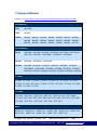
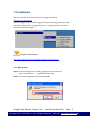
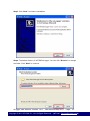
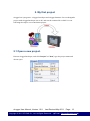
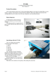
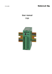
eLogger User Manual Version 1.0.0, Jun 2011 Table of Contents 1. Introduction .............................................................................. 4 1.1 Features............................................................................ 4 1.2 Support Module ............................................................... 7 1.3 Installation ........................................................................ 9 2. My first project ...................................................................... 12 2.1 Open a new project. ....................................................... 12 2.2 Interface description...................................................... 13 2.3 System Setting ............................................................... 13 2.4 Add Driver ...................................................................... 14 2.5 Add Device ..................................................................... 15 2.6 Add Tags ........................................................................ 16 2.7 Edit Page ........................................................................ 17 2.8 Run eLogger Runtime on PAC ...................................... 17 2.9 Upload project frome eLogger Developer .................... 19 3. Support Driver ...................................................................... 20 3.1 Module on slot ............................................................... 20 3.2 Modbus TCP ................................................................... 23 3.3 Modbus Serial ................................................................ 28 4.Tag Mapping ........................................................................... 33 4.1 Add new Tags ................................................................ 34 4.2 Edit Tag (support batch edit) ........................................ 35 4.3 Scaling ............................................................................ 36 4.4 Delete Tag ...................................................................... 36 5.Layout Pages .......................................................................... 37 5.1 Page Menu ...................................................................... 37 5.2 Design Page ................................................................... 38 5.3 Button type ..................................................................... 39 1. Introduction eLogger is a free charge and easy-to-use software to implement HMI and data logger on our Windows CE.NET 5.0 based PACs (WinPAC and ViewPAC) for simple I/O monitoring and controlling systems. It can save your money and shorten time-to-market. eLogger can quickly and easily develop an application with flexible I/O configuration. The developing can be completed in just 5 simple steps: configuring I/O modules, configuring data logger, designing HMI layout pages, uploading the project to WinPAC/ViewPAC, running it. In the simple steps, there is no need of software programming knowledge. And if you want to add more powerful functions, eLogger also provides a flexible “shared memory” interface to allow your VS.NET and ISaGRAF programs co-work with it. 1.1 Features 1.1.1 PAC Support Developer:Windows 2K、Windows XP、Windows Vista、Windows7 Runtime target: Windows CE.NET 5.0 platform WinPAC series, ViewPAC series Windows CE.NET 6.0 platform XP-8000-CE6, XP-8000-Atom-CE6 Windows XPE platform XP-8000, XP-8000-Atom 1.1.2 Support Driver Math Curve(For Demo) Module on slot Modbus serial master( Support Modbus RTU/Modbus ASCII) Modbus TCP master eLogger User Manual, Version 1.0.0. Last Revised:May 2011 Copyright © 2011 ICP DAS Co., Ltd. All Rights Reserved. Page:4 ★E-mail:[email protected]★ 1.1.3 HMI Components:Button、Text Box、Linear Gauge、Angular Gauge、LED、 Switch、Tank、Label、Plot、Seven Segment、Thermometer、Slider、Odometer Pages:Max of 32 pages. 1.1.4 Real Time Data Trend:Max. of 5 trend line in one plot. 1.1.5 Value Scaling: Set gain and offset can scale analog values from volt or amp unit to another physical unit. For example: rpm for rotation, kg for weight. 1.1.6 Account Management 3 levels operating management: Admin, Power User, User Admin Power User User Open project Start/Stop project Set AO/DO values Switching group pages . : allowed : not allowed eLogger User Manual, Version 1.0.0. Last Revised:May 2011 Copyright © 2011 ICP DAS Co., Ltd. All Rights Reserved. Page:5 ★E-mail:[email protected]★ 1.1.7 Remote Maintenance You can use eLogger Developer’s remote control function to Upload / Run / Stop the project through the Ethernet. 1.1.8 Database Local database. Remote database(not avalible): SQL server on windows platform. 1.1.9 Logic Control Programming Via the " shared memory " , you can choose ISaGRAF or VS.Net to develop a logic control program and co-work with the elogger. Your programs can access the data of I/O module and exchange other temporary data through the "shared memory". You can focus on the logic control programming. ISaGRAF (IEC61131-3 standard PLC languages) (Refer to ISaGRAF FAQ-115) Visual Studio .NET (C#, VB.NET) for Window CE.NET 5.0 eLogger User Manual, Version 1.0.0. Last Revised:May 2011 Copyright © 2011 ICP DAS Co., Ltd. All Rights Reserved. Page:6 ★E-mail:[email protected]★ 1.2 Support Module Support List :http://www.icpdas.com/products/PAC/winpac/io_support_list.htm 8K I/O Module 8K AI I8017HW 8K AO I8024W 8K DIO I8040W、I8041W、I8042W、I8046W、I8050W、I8051W、I8052W、 I8053W、I8054W、I8055W、I8056W、I8057W、I8058W、I8060W、 I8063W、I8064W、I8065W、I8066W、I8068W、I8069W、I8077W 87K I/O Module 87K AI I87005W、I87013W、I87015W、I87015PW、I87017RW、I87017RCW、 I87017A5、I87018W、I87018RW、I87018ZW、I87019RW 87K AO I87024W、I87024CW、I87028CW 87K DIO I87040W、I87041W、I87046W、I87051W、I87052W、I87053W、 I87053WA5、I87053WE5、I87054W、I87055W、I87057W、I87058W、 I87059W、I87063W、I87064W、I87065W、I87066W、I87068W、I87069W ET-7000 ET-7005、ET-7015、ET-7016、ET-7017、ET-7017-10、ET-7018Z、ET-7019、 ET-7026、ET-7042、ET-7044、ET-7050、ET-7051、ET-7052、ET-7053、ET-7060、 ET-7065、ET-7066、ET-7067 PET-7000 PET-7005、PET-7015、PET-7016、PET-7017、PET-7017-10、PET-7018Z、 PET-7019、PET-7026、PET-7042、PET-7044、PET-7050、PET-7051、PET-7052、 PET-7053、PET-7060、PET-7065、PET-7066、PET-7067 WISE WISE-7105、WISE-7115、WISE-7117、WISE-7118Z、WISE-7119、WISE-7126、 WISE-7144、WISE-7151、WISE-7152、WISE-7160、WISE-7167 eLogger User Manual, Version 1.0.0. Last Revised:May 2011 Copyright © 2011 ICP DAS Co., Ltd. All Rights Reserved. Page:7 ★E-mail:[email protected]★ M-7000 AI M7005、M7015、M7016、M7016D、M7017、M7017C、M7017R、 M7017RC、M7018、M7018R、M7019R、M7033、M7033D AO M7022、M7024 DIO M7041、M7041D、M7045、M7045D、M7050、M7050D、M7051、 M7051D、M7052、M7052D、M7053、M7053D、M7055、M7055D、 M7059D、M7060、M7060D、M7067、M7067D eLogger User Manual, Version 1.0.0. Last Revised:May 2011 Copyright © 2011 ICP DAS Co., Ltd. All Rights Reserved. Page:8 ★E-mail:[email protected]★ 1.3 Installation Please install .NET Framework 3.5 before eLogger installation. Microsoft.com downloads Execute eLogger setup to install eLogger Developer and eLogger Runtime. After installation, there will be “eLogger Developer”, “eLogger Runtime” shortcut in “Programs/ICPDAS/eLogger”. eLogger download path: http://ftp.icpdas.com/pub/cd/winpac/napdos/elogger/setup/ 1.3.1 Step by step Step1. Download eloggersetup_vAAA_yyyymmdd.exe, and execute it. AAA: Version number. yyyymmdd:Release date. Step2. Choose the language interface and click OK. eLogger User Manual, Version 1.0.0. Last Revised:May 2011 Copyright © 2011 ICP DAS Co., Ltd. All Rights Reserved. Page:9 ★E-mail:[email protected]★ Step3. Clcik “Next” to continue installation. Step4. The default folder is C:\ICPDAS\eLogger, You can click “Browser” to change the folder. Clcik” Next” to continue. eLogger User Manual, Version 1.0.0. Last Revised:May 2011 Copyright © 2011 ICP DAS Co., Ltd. All Rights Reserved. Page:10 ★E-mail:[email protected]★ Step5. Clcik “Install”. Step6. Click “Finish” to exit setup. eLogger User Manual, Version 1.0.0. Last Revised:May 2011 Copyright © 2011 ICP DAS Co., Ltd. All Rights Reserved. Page:11 ★E-mail:[email protected]★ 2. My first project eLogger has 2 programs:eLogger Developer and eLogger Runtime. You can designthe project with eLoggerDeveloper.exe on PC, and run the runtime file on PAC. You can following the steps to run a simulation project. 2.1 Open a new project. Execute eLoggerDeveloper, and click “Project”=>” New”, type the project name and choose open. eLogger User Manual, Version 1.0.0. Last Revised:May 2011 Copyright © 2011 ICP DAS Co., Ltd. All Rights Reserved. Page:12 ★E-mail:[email protected]★ 2.2 Interface description The left side of main interface is the project function list, the right side is the work area. 2.3 System Setting Click System and set the sampling time to 1 sec. eLogger User Manual, Version 1.0.0. Last Revised:May 2011 Copyright © 2011 ICP DAS Co., Ltd. All Rights Reserved. Page:13 ★E-mail:[email protected]★ 2.4 Add Driver Click Driver(New) , and choose a driver “Math Curve”, then click “Next”. Click “Install” to add the driver to project. eLogger User Manual, Version 1.0.0. Last Revised:May 2011 Copyright © 2011 ICP DAS Co., Ltd. All Rights Reserved. Page:14 ★E-mail:[email protected]★ 2.5 Add Device Click “Math Curve” and press the “+Device” button of the driver form. Choose “Sin” mode of the device. You will see a device was add in the list. The device has 2 simulation value “Sin” and “Rnd”. eLogger User Manual, Version 1.0.0. Last Revised:May 2011 Copyright © 2011 ICP DAS Co., Ltd. All Rights Reserved. Page:15 ★E-mail:[email protected]★ 2.6 Add Tags Click “AI Tag”, You will see the memory mapping on the right side. The device “MathCurvID1” used InputRegister 0~1 to save it’s “Sin” and “Rnd” values. You can click “New Tag” to add 2 tags. Then you can select the rows of the tag list, and set the memory address to 0.AI0’s memory address will be set to 0, and AI1’s will be 1. Now we have 2 tags (AI0, AI1), and they are point to Input Register [0] and [1]. eLogger User Manual, Version 1.0.0. Last Revised:May 2011 Copyright © 2011 ICP DAS Co., Ltd. All Rights Reserved. Page:16 ★E-mail:[email protected]★ 2.7 Edit Page Click “Page0”, click the textbox on the toolbar to add 2 textbox on the page. Select the textbox, and choose the tag name in property window. 2.8 Run eLogger Runtime on PAC Copy the runtime files to PAC. For_WinPAC support WinPAC series, ViewPAC series For_XP8000CE6 supports XP-8000-CE6, XP-8000-Atom-CE6 For_XP8000WES supports XP-8000, XP-8000-Atom eLogger User Manual, Version 1.0.0. Last Revised:May 2011 Copyright © 2011 ICP DAS Co., Ltd. All Rights Reserved. Page:17 ★E-mail:[email protected]★ Then execute RuntimeXXXX.exe. eLogger User Manual, Version 1.0.0. Last Revised:May 2011 Copyright © 2011 ICP DAS Co., Ltd. All Rights Reserved. Page:18 ★E-mail:[email protected]★ 2.9 Upload project frome eLogger Developer Click eLogger Developer’s “Project” => “Remote Machine”. Type PAC’s IP address, then click “Upload Project”. After the runtime program received the project, you can click “Run” to run the project. eLogger User Manual, Version 1.0.0. Last Revised:May 2011 Copyright © 2011 ICP DAS Co., Ltd. All Rights Reserved. Page:19 ★E-mail:[email protected]★ 3. Support Driver eLogger driver communicate with the IO modules, and save the IO values to the shared memory. Here are the eLogger support driver lists, and the chapter will show you how to setup the driver Module on slot Modbus TCP Modbus Serial 3.1 Module on slot This driver support the I-8K, I-87K module on PAC’s slot. Step1. Install Driver eLogger User Manual, Version 1.0.0. Last Revised:May 2011 Copyright © 2011 ICP DAS Co., Ltd. All Rights Reserved. Page:20 ★E-mail:[email protected]★ Step2. Add Device Choose a module, and set it’s slot number, then click “Add”. The device and it’s channels will be on the lists. eLogger User Manual, Version 1.0.0. Last Revised:May 2011 Copyright © 2011 ICP DAS Co., Ltd. All Rights Reserved. Page:21 ★E-mail:[email protected]★ You can edit the channel’s note. The channels will map to the shared memory. You can see them on “Tag Mapping”. eLogger User Manual, Version 1.0.0. Last Revised:May 2011 Copyright © 2011 ICP DAS Co., Ltd. All Rights Reserved. Page:22 ★E-mail:[email protected]★ 3.2 Modbus TCP This driver supports ICPDAS Modbus TCP modules, and standard Modbus TCP devices. The driver uses Modbus command : FC1 Read multiple coils status (0xxxx) for DO FC2 Read multiple input discretes (1xxxx) for DI FC3 Read multiple registers (4xxxx) for AO FC4 Read multiple input registers (3xxxx) for AI FC5 Write single coil (0xxxx) for DO FC6 Write single register (4xxxx) for AO Step1. Install Driver eLogger User Manual, Version 1.0.0. Last Revised:May 2011 Copyright © 2011 ICP DAS Co., Ltd. All Rights Reserved. Page:23 ★E-mail:[email protected]★ Step2. Add IP address. The driver will create a tcp connection for each IP address. Step3. Add Device. eLogger User Manual, Version 1.0.0. Last Revised:May 2011 Copyright © 2011 ICP DAS Co., Ltd. All Rights Reserved. Page:24 ★E-mail:[email protected]★ Select a connection IP, type a name for identification, and set the device’s station address (in other words ID or station ID). And then click “Add Register”. Choose a module, and the register will be filled automatically. eLogger User Manual, Version 1.0.0. Last Revised:May 2011 Copyright © 2011 ICP DAS Co., Ltd. All Rights Reserved. Page:25 ★E-mail:[email protected]★ Choose “Enter Number” for filling the registers manually. After the registers were added, click “Add” to add the device. eLogger User Manual, Version 1.0.0. Last Revised:May 2011 Copyright © 2011 ICP DAS Co., Ltd. All Rights Reserved. Page:26 ★E-mail:[email protected]★ You can edit the channel’s note. The channels will map to the shared memory. You can see them on “Tag Mapping”. eLogger User Manual, Version 1.0.0. Last Revised:May 2011 Copyright © 2011 ICP DAS Co., Ltd. All Rights Reserved. Page:27 ★E-mail:[email protected]★ 3.3 Modbus Serial This driver supports ICPDAS Modbus RTU modules, and standard Modbus RTU/ASCII devices. The driver uses Modbus command : FC1 Read multiple coils status (0xxxx) for DO FC2 Read multiple input discretes (1xxxx) for DI FC3 Read multiple registers (4xxxx) for AO FC4 Read multiple input registers (3xxxx) for AI FC5 Write single coil (0xxxx) for DO FC6 Write single register (4xxxx) for AO Step1. Install Driver eLogger User Manual, Version 1.0.0. Last Revised:May 2011 Copyright © 2011 ICP DAS Co., Ltd. All Rights Reserved. Page:28 ★E-mail:[email protected]★ Step2. Add COM port that connect to the Modbus serial devices. Step3. Add Device. eLogger User Manual, Version 1.0.0. Last Revised:May 2011 Copyright © 2011 ICP DAS Co., Ltd. All Rights Reserved. Page:29 ★E-mail:[email protected]★ Select a connection COM port, type a name for identification, and set the device’s ID (in other words ID address, station ID, or address). And then click “Add Register”. Choose a module, and the register will be filled automatically. eLogger User Manual, Version 1.0.0. Last Revised:May 2011 Copyright © 2011 ICP DAS Co., Ltd. All Rights Reserved. Page:30 ★E-mail:[email protected]★ Choose “Enter Number” for filling the registers manually. After the registers were added, click “Add” to add the device. eLogger User Manual, Version 1.0.0. Last Revised:May 2011 Copyright © 2011 ICP DAS Co., Ltd. All Rights Reserved. Page:31 ★E-mail:[email protected]★ You can edit the channel’s note. The channels will map to the shared memory. You can see them on “Tag Mapping”. eLogger User Manual, Version 1.0.0. Last Revised:May 2011 Copyright © 2011 ICP DAS Co., Ltd. All Rights Reserved. Page:32 ★E-mail:[email protected]★ 4.Tag Mapping The “Tag Mapping” lists channels of all devices added in the project, and automatically arrays them by Shared Memory addresses sequentially. You can add new tags and assign them to specific Shared Memory addresses. The following description will show you how to set Tag property. Shared Memory address starts from ”0” eLogger User Manual, Version 1.0.0. Last Revised:May 2011 Copyright © 2011 ICP DAS Co., Ltd. All Rights Reserved. Page:33 ★E-mail:[email protected]★ 4.1 Add new Tags Step1. Select the Tag list Step2. Press “New Tag” -> enter the number of new tags -> “OK” Step3. Select Tag(you also can drag to select all tags with left mouse button) Step4. Enter the Shared Memory address eLogger User Manual, Version 1.0.0. Last Revised:May 2011 Copyright © 2011 ICP DAS Co., Ltd. All Rights Reserved. Page:34 ★E-mail:[email protected]★ 4.2 Edit Tag (support batch edit) Tag Name: You can specify a name easy to identify. Description: You can edit the tag’s description. Data Type: Select the input/output type of channel Data Type Shared Memory address cost 16-bit Signed Integer 1 16-bit Unsigned Integer 1 32-bit Signed Long 2 32-bit Unsigned Long 2 32-bit Float 2 Gain, Offset: Set gain and offset can scale the memory value to another physical unit. To obtain these two values first find out two sets of value and do operation by the formula provided below.(Example: display the temperature -270~270) eLogger User Manual, Version 1.0.0. Last Revised:May 2011 Copyright © 2011 ICP DAS Co., Ltd. All Rights Reserved. Page:35 ★E-mail:[email protected]★ 4.3 Scaling The scaling tool helps you automatically get the “Gain” value and ”Offset” value. Press the “Scaling” button, select the “Channel Type” you need, and then press “OK” button. 4.4 Delete Tag eLogger User Manual, Version 1.0.0. Last Revised:May 2011 Copyright © 2011 ICP DAS Co., Ltd. All Rights Reserved. Page:36 ★E-mail:[email protected]★ 5.Layout Pages 5.1 Page Menu New: Add a new page to design. Rename: Select an exist page, and click “Rename”, and then enter new name. Remove: Select an exist page, and click “Remove”. Import: Import page file. Export: Export page file. eLogger User Manual, Version 1.0.0. Last Revised:May 2011 Copyright © 2011 ICP DAS Co., Ltd. All Rights Reserved. Page:37 ★E-mail:[email protected]★ 5.2 Design Page Step1. Select a page to edit. Step2. The default page size is 640X480, you can change size by “Layout Size”. Step3. In the component list, add a proper component into the page by “click”. Step4. Select the object and set its property (select “Tag Type” -> select “Tag Name”). eLogger User Manual, Version 1.0.0. Last Revised:May 2011 Copyright © 2011 ICP DAS Co., Ltd. All Rights Reserved. Page:38 ★E-mail:[email protected]★ 5.3 Button type Button type Description Run “Start” and “Stop” project. Simulation Simulation value. SwitchPage Switch the page, you have to assign the page name. Exit Return to eLogger Runtime menu. LogIn Enter password to log in “power user” or “Admin”. eLogger User Manual, Version 1.0.0. Last Revised:May 2011 Copyright © 2011 ICP DAS Co., Ltd. All Rights Reserved. Page:39 ★E-mail:[email protected]★