1
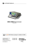
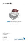
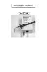
WWW.
.COM
Version 2.0
REF 75501
STANDARD IMAGING, INC.
3120 Deming Way
Middleton, WI 53562-1461
TEL 800.261.4446
TEL 608.831.0025
FAX 608.831.2202
July / 2008 ©2008 Standard Imaging, Inc.
DOC #80457-03
General Precautions
CAUTION:
Do not connect the electrometer’s RS-232 serial port to
the telephone line. This port is
for connection to equipment
where no risk of external voltage exists.
Warnings and Cautions alert users to
dangerous conditions that can occur if
instructions in the manual are not obeyed.
Warnings are conditions that can cause
injury to the operator, while Cautions can
cause damage to the equipment.
CAUTION:
This program is designed
for use with the MAX 4000
with firmware version 4.4
and higher and MAX 4001
with firmware 1.0 and higher
only.
CAUTION:
To minimize the potential for
computer issues, do not run
the MAX COMM Software concurrently with other software
programs.
CAUTION:
The MAX COMM Software
requires the input of data
with proper units to function
correctly.
Table of Contents
PAGE
2 General Precautions
3 Overview
4 Software Installation
4 MAX COMM Setup
6 Using Brachytherapy or External Beam Libraries
9 Performing Brachytherapy Measurements
12 Performing External Beam Measurements
15 Explanation of Use with Protocols
17 Explanation of Saved File Export
18 Software Requirements and Specifications
19 Service Policy
19 Customer Responsibility
20 Warranty
3120 DEMING WAY
MIDDLETON, WI 53562-1461 USA
WWW.STANDARDIMAGING.COM
Overview
MAX COMM Software is designed to be an
advanced communication and control application for use with the Standard Imaging
MAX 4000 and MAX 4001 Electrometers.
The user can create and store a large library
of Electrometers and Ionization Chambers
including the calibration factors that can
be applied to measurement data. Using
the measurement functions, the user can
remotely control their electrometer and
retrieve data on their computer. From here,
the calibration factors and temperature and
pressure corrections can automatically be
applied. The option to print the measurement
form also exists along with the ability to save
the measurement data to file.
Operating with this program requires a MAX
4000 with firmware version 4.4 or higher
or MAX 4001 with firmware 1.0 or higher
to take advantage of the communication
components in both library and measurement modes. To ensure your electrometer
is compatible with the MAX COMM Software, please contact Standard Imaging for
more information on how to upgrade your
electrometer’s firmware.
Software Installation
MAX COMM Software is distributed via CD-ROM directly from Standard Imaging. To use the
software, run the install program from the CD. Once the program has been installed to your
hard disk, a shortcut will be added to your desktop and Start menu. Ensure a MAX 4000 or
MAX 4001 Electrometer is properly connected to the serial port on the computer when utilizing the communication functions of this program.
Visit www.standardimaging.com for new MAX COMM Software version information and
availability.
MAX COMM Setup
Equipment Setup
Instructions for MAX 4000 (serial number
starting with E) and MAX 4001 units
Using the DB-9 adaptor and 4 wire phone
cable supplied with your electrometer, connect the adapter to an open serial port on
the PC on which you intend to install the
MAX COMM Software. Connect one end of
the phone cord to the adaptor and the other
end to the RJ-11 connector on the MAX 4000
or MAX 4001. It is not necessary to have
your PC powered down to either connect or
disconnect the electrometer from the serial
port. Refer to Figure 1.
Figure 1: Connecting a MAX 4000 (serial number starting with E) or MAX 4001 Electrometer
to a PC
NOTE: Use only the adaptor supplied with
the electrometer.
Instructions for MAX 4000 (serial number
starting with F)
Using the serial cable supplied with your
electrometer, connect the MAX 4000 to an
open serial port on the PC on which you
intend to install the MAX COMM Software.
It is not necessary to have your PC powered
down to either connect or disconnect the
electrometer from the serial port. Refer to
Figure 2.
Figure 2: Connecting a MAX 4000 Electrometer
(serial number starting with F) to a PC
MAX COMM Setup Continued
Main Menu
Upon first starting MAX COMM, you will have
four options available.
Setup - Select communication port settings,
and standard temperature and pressure.
Brachytherapy - This takes you to the
Brachytherapy Library for adding chambers,
electrometers, or systems to your library.
Once you have created your library, select
the chamber and calibration you want to
use, then proceed to the Measure screen
to collect measurements and perform calculations.
External Beam - This takes you to the External Beam Library for adding chambers,
electrometers, or systems to your library.
Once you have created your library, select
the chamber and calibration you want to
use, then proceed to the Measure screen
to collect measurements and perform calculations.
MAX COMM Main Menu
QUIT - Ends the current MAX COMM session.
The above options are available from the
menu bar located on the bottom of each
screen of MAX COMM for quick navigation.
In the setup menu of MAX COMM, confirm
the settings are appropriate for your system
configuration. Click [Auto] to attempt to configure your COM port settings automatically.
If the COM port cannot be automatically
determined, select the appropriate number
(COM 1-8) from the Select Communication
Port pull down menu. Click [Test] to confirm
if your MAX electrometer and MAX COMM
are communicating properly.
Select the standard temperature and standard pressure values to match the values
on your calibration report. These values will
vary depending on which country you are in
and its corresponding standards.
MAX COMM Setup Screen
These settings will be saved by the software
and, if you have not changed your operational parameters, do not need to be selected
each time the program is loaded.
Using Brachytherapy or External Beam Libraries
By choosing either Brachytherapy or External Beam from the main menu of MAX
COMM, the corresponding library screen
is opened. From here, the option to create
new library entries, edit existing chamber or
electrometer profiles, or create/edit systems
becomes available.
When clicking [new], a dialog box appears
prompting for the name of the chamber,
electrometer or system depending on which
was selected.
Brachytherapy Library Screen
Creating a New Chamber Profile
1.
Click [new] adjacent to Ion Chambers.
2.
Enter in the model name and serial
number of the chamber you wish to
add and click [OK]. If you are entering
a chamber within the Brachytherapy
Library, you will be prompted to choose
between an IVB or LDR/HDR source
type calibration. Likewise, if you are
entering a chamber within the External
Beam Library, you will be prompted to
choose between an air or water calibration type.
3.
Enter the required fields for
brachytherapy or external beam chambers. Click [save] to return to the library
interface screen.
2
From the main library screen you can edit
a chamber’s attributes by selecting it from
the list and clicking [edit]. All values can be
modified, excluding model name and serial
number.
NOTE: You are not required to enter all of the
calibration factors listed on the library screen.
Enter only those factors that you use.
Chamber Details
Using Brachytherapy or External Beam Libraries
Creating a New Electrometer Profile
1.
2.
Click [new] adjacent to Electrometers
on the Brachytherapy or External Beam
Library screen.
2
Select between MAX 4000 or MAX
4001, and enter the serial number of
the electrometer you wish to add to the
library.
NOTE: It is important to enter the electrometer serial number correctly. Measurements
can not be taken unless the electrometer serial number matches that from the library.
3.
Enter the calibration report number and
date, charge high range, charge low
range, current high range, and current
low range calibration factors. Click
[save] to store the entry and return to
the library interface screen.
NOTE: From the main library screen you can
edit an electrometer’s attributes by selecting
it from the list and clicking [edit]. All values
can be modified excluding model name and
serial number.
Electrometer Details
Get Attached Meter
If a MAX 4000 or MAX 4001 is attached, the
[Get Attached Meter] button can be clicked to
add it to the library. If it is new to the library,
MAX COMM will retrieve the model and serial
number from the electrometer and prompt
you for calibration information. Click [save]
to add to the library.
NOTE: If no electrometer or an incompatible
device is connected to the serial port, a warning will display aborting the operation.
Using Brachytherapy or External Beam Libraries
Creating a New System Profile
1.
Select [system library] on the top right
corner of the screen, and click [new]
adjacent to Systems.
2.
Enter a name for the system you wish
to create.
3.
Enter the chamber model and serial
number, electrometer model and serial
number, and system calibration factor.
The chamber and electrometer values
do not relate to the chambers and
electrometers already entered into the
library. These are independent entries
from the individual components library.
Click [save] to return to the library interface screen.
Brachytherapy System Factor Display
2
On the main library screen you can edit a
system’s attributes by selecting it from the list
and clicking [edit]. All values can be modified
excluding the system factor name.
NOTE: It is important to enter the electrometer serial number correctly. Measurements
can not be taken unless the electrometer serial number matches that from the library.
To Proceed to Measurement
From the library screen, select the chamber
and electrometer or system being used.
Select the calibration factor to apply to the
measurements, then proceed to the measure
screen by clicking [Measure] from the bottom
row of menu buttons. The selected values
will transfer to the measurement screen for
calculations.
Editing Brachytherapy System Factor
Performing Brachytherapy Measurements
The Brachytherapy Measurements screen
allows you to control and receive data from
the electrometer, calculate the average
measurement, and calculate M by applying
correction factors. Begin by confirming the
system factor or chamber and electrometer attributes that were selected from the
Brachytherapy Library.
1. If the correct system or chamber and
electrometer are displayed, set the
values for Range, Bias and select the
Rate or Charge Mode as desired.
If selecting Charge, choose the collection mode from the adjacent pull down
menu. There are three charge collection
modes:
•
•
•
2.
Brachytherapy Measurements Screen
for Ion Chamber and Electrometer Selection
Timed (select a collection interval
in 15 second increments)
Continuous “CON” (charge will
collect for an unlimited duration)
Triggered “TRG” (charge will
collect when the signal rises
above and drops below configured
thresholds, see MAX 4000 manual
for information on how to configure
threshold values)
Click on the [Set Meter] button to set the
electrometer to the values selected in
step 1.
N O T E : Yo u m u s t c l i c k t h e
[Set Meter] button to send the configuration to the electrometer each time you
make a change to the configuration. A
setting change will not be updated in
the electrometer until this is performed,
and no other MAX COMM electrometer
functions can be performed.
Brachytherapy Measurements Screen
for System Factor
3.
Allow the system to warm up and settle
for 10 minutes and then click “Zero
System”.
NOTE: A system zero can be performed
by clicking [Zero System] at any time. It
is advised to wait until the electrometer
and chamber combination is warmed
up before zeroing the electrometer.
A message is displayed on screen to
indicate the zero is taking place. Zeroing takes approximately 60 seconds to
complete.
Performing Brachytherapy Measurements Continued
4.
Additional Measurement Options
If desired, select additional options for the
measurement. The Set Meter command
does not need to be used when selecting
between these options.
Streaming
When performing a rate measurement,
Streaming can be checked which allows
selection between 2 Hz and 10 Hz acquisition rates.
2 Hz - default acquisition rate.
10 Hz - signal data is acquired unfiltered
NOTE: Depending on the capabilities of the
ion chamber used, 10 Hz operation may give
unexpected results.
When operating in rate streaming mode, a
duration must be entered. When measurement begins, a series of rate measurement
points will be collected.
Cumulative
When performing a charge measurement,
select Cumulative to capture a value each
second as charge collects.
Repeating
When performing a charge measurement,
select Repeating to capture a series of timed
charge collections. Enter a value in the collections box for the total charge collections
desired.
NOTE: Repeating mode only applies to a
timed charge collection. Continuous and
trigger modes do not apply.
Clicking [Retrieve] will request data
from the electrometer based on the settings entered in step 1 and display it in
the column below the retrieve button. In
Rate Mode, clicking [Retrieve] will display one collected value immediately,
while Charge Mode will collect charge
over the duration set in step 1 and then
return the value. The maximum collection time is 10 minutes (600 seconds).
If CON is chosen for a collection time, the
electrometer will collect charge until told to
stop. A dialog box will appear prompting
the user to stop the charge collection. Click
[Stop] to end the charge collection and return
the value. The total collection time will then
be displayed in seconds.
NOTE: Repeat this step as many times as
needed. You can omit values from the calculations by clicking the check box next to
the value. (Calculations will not be updated
until you click calculate again.)
Clicking [Clear Data] will delete all data
from the list.
5.
Enter the temperature and pressure of
the chamber at the time of measurements.
6. Click [Calculate] to determine the values for PTP and M. Mraw is the average
of the values retrieved in step 3 from
the electrometer.
NOTE: Brachytherapy calibrations are usually in units of Amperes and MAX COMM
uses Amperes for calibration factors and
calculations. Therefore when data is taken
in the Charge mode this data is divided by
the collection time when calculating M. If the
meter is set to MAX run instead of a timed
collection period, M will not be computed and
N/A will be displayed.
10
Performing Brachytherapy Measurements Continued
Clicking [Save] will give you a tabular file output of the information from this calculation.
An explanation of the format of this file can be
found on page 17 of this user manual.
Clicking [Print] will print a screen capture of
this screen to the current default printer.
11
Performing External Beam Measurements
The External Beam Measurements screen
allows you to control and receive data from
the electrometer, calculate the average
measurement, and calculate M by applying
correction factors. Begin by confirming the
system factor or chamber and electrometer
attributes that were selected from the External Beam Library.
1. If the correct system or chamber, and
electrometer are displayed, set the
values for Range, Bias and select the
Rate or Charge Mode as desired.
External Beam Measurements Screen for Ion
Chamber and Electrometer Selection
If selecting Charge, choose the collection mode from the adjacent pull down
menu. There are three charge collection
modes:
•
•
•
Timed (select a collection interval
in 15 second increments)
Continuous “CON” (charge will
collect for an unlimited duration)
Triggered “TRG” (charge will
collect when the signal rises
above and drops below configured
thresholds, see MAX 4000 manual
for information on how to configure
threshold values)
2.
Click on the [Set Meter] button to set the
electrometer to the values selected in
step 1.
NOTE: You must click the [Set Meter]
button to send the configuration to the
electrometer each time you make a
change to the configuration. A setting
change will not be updated in the electrometer until this is performed, and no
other MAX COMM electrometer functions can be performed.
3.
Allow the system to warm up and settle
for 10 minutes and then click “Zero
System”.
External Beam Measurements Screen
for System Factor
NOTE: A system zero can be performed
by clicking [Zero System] at any time. It
is advised to wait until the electrometer
and chamber combination is warmed
up before zeroing the electrometer.
A message is displayed on screen to
indicate the zero is taking place. Zeroing takes approximately 60 seconds to
complete.
12
Performing External Beam Measurements Continued
4.
Clicking [Retrieve] will request data
from the electrometer based on the settings entered in step 1 and display it in
the column below the retrieve button. In
Rate Mode, clicking [Retrieve] will display one collected value immediately,
while Charge Mode will collect charge
over the duration set in step 1 and then
return the value. The maximum collection time is 10 minutes (600 seconds).
If CON is chosen for a collection time,
the electrometer will enter a continuous
charge collection mode and collect
charge until told to stop. A dialog box
will appear prompting the user to stop
the charge collection. Click [Stop] to
end the charge collection and return
the value. The total collection time will
then be displayed in seconds.
If TRG is chosen for a collection time,
the electrometer will run in threshold
detection charge collection mode, using
the threshold levels set within the electrometer. The electrometer will start and
stop charge collections automatically
(see electrometer user manual). MAX
COMM will retrieve completed charge
collections continuously until the stop
button is pressed.
Additional Measurement Options
If desired, select additional options for the
measurement. The Set Meter command
does not need to be used when selecting
between these options.
Streaming
When performing a rate measurement,
Streaming can be checked which allows
selection between 2 Hz and 10 Hz acquisition rates.
2 Hz: default acquisition rate
10 Hz: signal data is acquired unfiltered
NOTE: Depending on the capabilities of the
ion chamber used, 10 Hz operation may give
unexpected results.
When operating in rate streaming mode, a
duration must be entered. When measurement begins, a series of rate measurement
points will be collected.
Cumulative
When performing a charge measurement,
select Cumulative to capture a value each
second as charge collects.
Repeating
When performing a charge measurement,
select Repeating to capture a series of timed
charge collections. Enter a value in the collections box for the total charge collections
desired.
NOTE: Repeating mode only applies to a
timed charge collection. Continuous and
trigger modes do not apply.
NOTE: Repeat this step as many times
as needed. You can omit values from
the calculations by clicking the check
box next to the value. (Calculations will
not be updated until you click calculate
again.)
Clicking [Clear Data] will delete all data
from the list.
5.
Enter the temperature and pressure for
the chamber at the time of measurement.
6. Click [Calculate] to determine the values for PTP and M. Mraw is the average
of the values retrieved in step 3 from
the electrometer.
13
Performing External Beam Measurements Continued
NOTE: External Beam calibrations are usually in units of coulombs and MAX COMM
uses coulombs for calibration factors and
calculations. Therefore when data is taken
in the Rate mode this data cannot be used
when calculating M. If the meter is set to Rate
mode, M will not be computed and N/A will
be displayed.
Clicking [Save] will give you a tabular file output of the information from this calculation.
An explanation of the format of this file can be
found on page 17 of this user manual.
Clicking [Print] will print a screen capture of
this screen to the current default printer.
14
Explanation of Use with Protocols
NOTE: The quantity called M as output
needs to be interpreted according to the
measurements being done by the user.
For example, if measurements are being made for chamber recombination, the
measurements should be manipulated by
the appropriate equation according to the
protocol being used. The interpretations
given below are for External Beam TG-21,
TRS-277, TG-51, or TRS-398 protocols. The
interpretations for brachytherapy are based
upon TG-43 or TG-60. If alternative protocols
are being used or if other measurements are
being done, the value of M needs appropriate
interpretation.
The quantity given by MAX COMM is “M”,
which is the average of the corrected measured value. This quantity is to be used in
the given protocol you are using to determine
absorbed dose in water. The symbols given
by MAX COMM correspond to the protocol in
use depending on the calibration value given,
e.g. NK. These uses are reviewed below.
I. EXTERNAL BEAM
For AAPM TG-21 or IAEA TRS-277, NX or NK
is used to find Ngas (TG-21) or ND (TRS-277).
See SI Tech Note 4532. Note that the value of
Ngas or ND also can be entered into the library
of MAX COMM, but these values will have to
be calculated from the calibration value of NK.
Note that the value of M is given as:
1. AAPM TG-21
The absorbed dose rate to water per U, monitor units or minutes, equation is given by:
where U is monitor units or minutes. For
interpretation of other symbols see the protocol. The M given by the MAX COMM is
with a value of N, which may be Ngas if it was
entered into the library. If Ngas was used the
equation above becomes:
If NK was used instead of Ngas, then
Therefore the equation to be used is re-expressed as:
2. IAEA TRS-277
The absorbed dose to water equation is
given by:
where N is the calibration value or the calculated value from the calibrated value. Refer
to the appropriate protocol for further details;
the equations for absorbed dose to water for
each protocol are given to the right:
For interpretation of other symbols see the
protocol. The M given by the MAX COMM is
Mu with a value of N, which may be ND if it
was entered into the library. If ND was used
the equation above becomes:
15
Explanation of Use with Protocols Continued
II. BRACHYTHERAPY
If NK was used instead of ND then
Therefore the equation to be used is reexpressed as:
3. AAPM TG-51 and TRS-398
The absorbed dose to water equation is
given by:
For interpretation of other symbols see the
appropriate protocol. The M given by the
MAX COMM is M with the value of
expressed as ND,w. Therefore the equation
above becomes:
1. For Photon Beams
The appropriate equation from AAPM protocol TG-43 or IAEA-TECDOC-1274 is:
where SK is measured directly and termed
M in MAX COMM.
2. For Beta Particles
The appropriate equation from AAPM protocol TG-60 or IAEA-TECDOC-1274 is:
where
is measured directly using
N2mm and termed M in MAX COMM.
16
Explanation of Saved File Export
When saving measurement data from the calculate portion of MAX COMM, the default file
type is a *.csv file, (comma separated value), that can be directly opened with any spread
sheet application. The resulting file will not have labels for the columns of data. Refer to this
chart to determine the identity of each data column.
Column Designation
Column Value
A (1)
Date of Calculation
B (2)
Time of Calculation
C (3)
M
D (4)
Aion
E (5)
PTP
F (6)
Chamber or System Calibration Factor
G (7)
Electrometer Calibration Factor (empty for systems)
H (8)
Mraw (average of measurements)
I (9)
Standard Temperature
J (10)
Chamber Temperature
K (11)
Standard Pressure
L (12)
Chamber Pressure
M (13)
Chamber Model
N (14)
Chamber Serial Number
O (15)
Electrometer Model
P (16)
Electrometer Serial Number
Q (17)
Range
R (18)
Bias
S (19)
Mode
T (20)
Collection Time
U (21)
Measurements
V (22)
Discarded Measurement Indicator
17
Software Requirements and Specifications
Hardware Configuration
Electrometer
MAX 4000 with firmware version 4.4 or
higher*, or MAX 4001 with firmware version 1.0 or higher.
Serial port
Intel-compatible Pentium 90 or higher
32MB of RAM
Minimum of 30 MB available
Connector Type
Processor
Memory
Hard Disk
Additional Hardware
4X CD-ROM Drive
RS-232 / Serial Port
Operating System
Windows 98/ME/2000/XP
* Depending on the age of your MAX 4000 Electrometer, firmware version may vary. Contact
Standard Imaging with your serial number for more information.
See www.standardimaging.com for applicable tech notes.
Specifications are subject to change without notice.
18
Service Policy
Customer Responsibility
If service, including recalibration, is required,
please contact Standard Imaging’s Customer
Service department by phone or email prior
to shipping the product. Standard Imaging’s
Customer Service and Technical Service
staff will attempt to address the product issue via phone or email. If unable to address
the issue, a return material authorization
(RMA) number will be issued. With the
RMA number, the product can be returned
to Standard Imaging. It is the responsibility
of the customer to properly package, insure
and ship the product, with the RMA number
clearly identified on the outside of the package. The customer must immediately file
a claim with their carrier for any shipping
damage or lost shipments. Return shipping
and insurance is to be pre-paid or billed to
the customer, and the customer may request
a specific shipper. Items found to be out of
warranty are subject to a minimum service
fee of 1 hour labor (excluding recalibrations)
for diagnostic efforts and require a purchase
order (PO) before service is performed. With
concurrence from customer, the product may
be replaced if it is unserviceable or if the
required service is cost prohibitive. Products
incurring service charges may be held for
payment. Standard Imaging does not provide
loaner products. See the Standard Imaging
Warranty and Customer Responsibility for
additional information.
This product and its components will perform
properly and reliably only when operated and
maintained in accordance with the instructions contained in this manual and accompanying labels. A defective device should not be
used. Parts which may be broken or missing
or are clearly worn, distorted or contaminated
should be replaced immediately with genuine
replacement parts manufactured by or made
available from Standard Imaging Inc.
Serialization Information
Standard Imaging products that are serialized contain coded logic in the serial number
which indicates the product, day and year of
manufacture, and a sequential unit number
for identification:
CAUTION: Federal law in the U.S.A.
and Canadian law restrict the sale,
distribution, or use of this product
to, by, or on the order of a licensed
medical practitioner. The use of
this product should be restricted
to the supervision of a qualified
medical physicist. Measurement of
high activity radioactive sources is
potentially hazardous and should be
performed by qualified personnel.
Should repair or replacement of this product
become necessary after the warranty period, the customer should seek advice from
Standard Imaging Inc. prior to such repair
or replacement. If this product is in need of
repair, it should not be used until all repairs
have been made and the product is functioning properly and ready for use. After repair,
the product may need to be calibrated. The
owner of this product has sole responsibility
for any malfunction resulting from abuse,
improper use or maintenance, or repair by
anyone other than Standard Imaging Inc.
The information in this manual is subject to
change without notice. No part of this manual
may be copied or reproduced in any form or
by any means without prior written consent
of Standard Imaging Inc.
A YY DDD X
A
YY
Unique product ID
Last two digits of the year
(e.g. 1999 = 99, 2000 = 00)
DDD Day of the year (1< DDD < 365)
X
Unique unit ID Number (1 < X < 9)
19
Warranty
Standard Imaging, Inc. sells this product under the warranty herein set forth. The warranty
is extended only to the buyer purchasing the product directly from Standard Imaging, Inc.
or as a new product from an authorized dealer or distributor of Standard Imaging, Inc.
For a period provided in the table below from the date of original delivery to the purchaser
or a distributor, this Standard Imaging, Inc. product, provided in the table is warranted
against functional defects in design, materials and workmanship, provided it is properly
operated under conditions of normal use, and that repairs and replacements are made in
accordance herewith. The foregoing warranty shall not apply to normal wear and tear, or
if the product has been altered, disassembled or repaired other than by Standard Imaging, Inc. or if the product has been subject to abuse, misuse, negligence or accident.
Product
Standard Imaging Ionization Chambers
Standard Imaging Well Chambers
Standard Imaging Electrometers
Standard Imaging BeamChecker Products
Standard Imaging Software Products
All Other Standard Imaging Products
Standard Imaging Custom Products
Standard Imaging Remanufactured Products
Standard Imaging Custom Select Products
Consumables
Serviced Product
Resale Products
ADCL Product Calibration
(Standard Imaging uses the UW-ADCL for
recalibrations required under warranty)
Warranty Period
2 years
2 years
2 years
2 years
1 year
1 year
1 year
180 days
90 days
90 days
90 days
As defined by the Original Equipment Manufacturer
0 - 90 days = 100% of ADCL Calibration Costs
91 - 182 days = 75% of ADCL Calibration Costs
183 – 365 days = 50% of ADCL Calibration Costs
366 – 639 days = 25% of ADCL Calibration Costs
(days from date of shipment to customer)
Standard Imaging’s sole and exclusive obligation and the purchaser’s sole and exclusive
remedy under the above warranties are, at Standard Imaging’s option, limited to repairing,
replacing free of charge or revising labeling and manual content on, a product: (1) which contains a defect covered by the above warranties; (2) which are reported to Standard Imaging,
Inc. not later than seven (7) days after the expiration date of the warranty period in the table;
(3) which are returned to Standard Imaging, Inc. promptly after discovery of the defect; and
(4) which are found to be defective upon examination by Standard Imaging Inc. Transportation
related charges, (including, but not limited to shipping, customs, tariffs, taxes, and brokerage
fees) to Standard Imaging are the buyer’s responsibility. This warranty extends to every part of
the product except consumables (fuses, batteries, or glass breakage). Standard Imaging, Inc.
shall not be otherwise liable for any damages, including but not limited to, incidental damages,
consequential damages, or special damages. Repaired or replaced products are warranted
for the balance of the original warranty period, or at least 90 days.
This warranty is in lieu of all other warranties, exclick or implied, whether statutory or otherwise,
including any implied warranty of fitness for a particular purpose. In no event shall Standard Imaging, Inc. be liable for any incidental or consequential damages resulting from the use, misuse
or abuse of the product or caused by any defect, failure or malfunction of the product, whether
a claim of such damages is based upon the warranty, contract, negligence, or otherwise.
This warranty represents the current standard warranty of Standard Imaging, Inc. Please refer
to the labeling or instruction manual of your Standard Imaging, Inc. product or the Standard
Imaging, Inc. web page for any warranty conditions unique to the product.
20