1
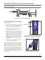
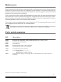
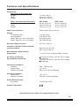
WWW. .COM DoseView 1D ™ REF 91800 / 91810 / 70800 STANDARD IMAGING, INC. 3120 Deming Way Middleton, WI 53562-2532 TEL 800.261.4446 TEL 608.831.0025 FAX 608.831.2202 Sep / 2012 ©2012 Standard Imaging, Inc. DOC #80487-05 General Precautions CAUTION: Proper use of this device depends on careful reading of all instructions and labels. CAUTION: Do not allow water or other liquids to enter the DoseView 1D Scanning Arm enclosure. Warnings and Cautions alert users to dangerous conditions that can occur if instructions in the manual are not obeyed. Warnings are conditions that can cause injury to the operator, while Cautions can cause damage to the device and internal electronics. CAUTION: Do not drop, mishandle, or disassemble this device. Refer all servicing to qualified individuals. CAUTION: Do not use the draining tube for filling the tank, as the components are not rated for high pressure throughput. CAUTION: Connector end of detector should not be submerged. 2 Table of Contents PAGE 2 General Precautions 3 Overview 4 Package Information 5 DoseView 1D Setup and Operation 8 Using the Hand Pendant 9 Maintenance 9 Parts and Accessories 10 Features and Specifications 11 Service Policy 11 Customer Responsibility 12 Warranty 3120 DEMING WAY MIDDLETON, WI 53562-1461 USA WWW.STANDARDIMAGING.COM Overview The DoseView 1D fulfills the requirements set forth by the AAPM TG-51 Protocol for a single dimension water scanning phantom. Determining the depth-dose curve and SAD measurements are easily done with the system. In addition, various points at various depths are quickly measured for the check of machine parameters and characterization. The DoseView 1D is a useful tool for dose assurance on a periodic basis. A rotary encoder (1000 pulses per revolution) is directly mounted to the leadscrew shaft. This prevents the problems typically associated with an encoder mounted to the motor shaft – which cannot take into account any backlash or elasticity in the mechanical linkage transferring the motion from the motor shaft to the leadscrew. An encoder directly mounted on the leadscrew is only sensing what is critically important – the direct movement of the leadscrew guiding the detector bracket. 3 Package Information This user manual covers the three packages in which Standard Imaging sells DoseView 1D components. See below for the list of the major components and accessories included with each REF number: REF 91800 Water tank (40x38x36 cm) REF 91810 REF 70800 X Water tank (32x28x36 cm) X Scanning arm X X X Hand pendant X X X Serial extension cable X X X AC power adapter X X X Draining tube X X Standard detector bracket X X X 4 DoseView 1D Setup and Operation 1 - Preparing the scanning arm Attach the AC power cable to the rear of the arm and plug the unit into a wall outlet. The two LEDs on the scanning arm indicate the following: Amber: Power indicator Green: Indicates successful self-test Attach the hand pendant directly to the serial cable attached to the scanning arm. The display will illuminate and initially show firmware versions for the arm "robot" and pendant. Next, "Not Initialized" will be displayed. CAUTION: Before initializing, ensure no obstructions will impede the detector carriage. To initialize, press and briefly hold the [ INITIALIZE ] button on the pendant until the detector carriage begins to move. The carriage will move to the top limit of arm travel and stop. The arm carriage is now free to move. Not Initialized Figure 1: DoseView 1D Scanning Arm rear status, hand pendant setup controls and display 2 - Aligning the water tank One side of the water tank does not have a black alignment line. This is the side on which the scanning arm mounts. Use the two black thumb screws to gently attach the arm approximately centered on the blank tank side. Place the tank and arm onto the treatment couch. Use the three vertical tank alignment lines to align the tank to isocenter, using available treatment room laser lines. Loosen the arm and move it until the light field or laser line matches the white line on the detector bracket. See Figure 2. Secure the scanning arm to the tank by tightening the two black thumb screws. Do not overtighten the screws, as a secure balance can be achieved without much force. Figure 2: Detector mount alignment line 5 DoseView 1D Setup and Operation Continued 3 - Attaching a detector 1 3 2 4 Figure 3: Attaching an ionization chamber For attaching a detector to the scanning arm, follow the instructions below and refer to Figure 3 above. 1. Select the desired detector and insert it into the hole in the blue detector bracket separated from the scanning arm. 2. Tighten the white thumb screw to secure the chamber into place. 3. Insert the black rod of the detector/ mount assembly into the scanning arm's blue bracket. Match the white alignment lines of both blue detector bracket pieces as shown in Figure 4. Align the detector with the light field adjusting the position from step 1 if necessary. 4. Alignment lines Figure 4: Detector mount alignment lines (stem shown transparent to show alignment) Tighten the white thumb screw to secure the assembly into place. Any thimble ion chamber should fit into the detector bracket holder, and most parallel plate chambers (which have a rigid stem) can be used with this detector bracket holder. For parallel plate chambers, simply insert the connector first into the holder, feed the cable through, and then tighten down the white thumbscrew when the chamber’s stem is in position. Figure 5: Fully mounted detector 6 DoseView 1D Setup and Operation Continued 4 - Filling the water tank Although the TG-51 protocol only requires a 20.0 cm travel depth, the Standard Imaging DoseView 1D scanning arm has 27.5 cm of end-to-end travel distance. The arm is intended to be used at a maximum of 25.0 cm depth, with added space at the top to match the chamber depth to the water surface and provide adequate spacing at the full depth of 25.0 cm. The tank label shown in Figure 6 shows the two minimum fill lines. If only 20.0 cm of depth travel is desired, simply fill water to at least the 20.0 cm fill line, and likewise for the 25.0 cm fill line. CAUTION: Do not use the draining tube for filling the tank, as the components are not rated for high pressure throughput. Figure 6: DoseView 1D tank minimum fill label 5 - Setting the Origin Using the hand pendant (see page 8), position the detector carriage at the desired origin position. To confirm the position, press and briefly hold the [ SET ORIGIN ] button. The display will show the current position as 0. NOTE: The carriage can be driven into either rail end without risk. However, for maximum longevity of the scanning arm, it is recommended that this be avoided other than during initialization. Also, if a rail end is hit at fast speed, the carriage must be moved away from the end at fast speed. If the end is hit at slow speed, either speed will move the carriage away from the rail end. 6 - Operating the scanning arm from outside of the treatment vault Disconnect the hand pendant from the scanning arm and in its place, attach the provided 9-pin serial extension cable. Run this cable outside of the treatment vault and re-connect the hand pendant. See Figure 7. The pendant will re-power on, display the current detector position and be ready for positioning the detector in the desired measurement location(s). Vault wall Figure 7: Hand pendant connection 7 DoseView 1D Setup Continued 7 - Draining the water tank Attach the included draining tube to the valve located at the bottom of the water tank. The water will drain automatically. Press the round button on the valve to release the draining tube. See Figure 8. Press to release draining tube Insert draining tube here NOTE: Water should be drained after each use to maximize the longevity and performance of the scanning arm and water tank. Figure 8: Water tank drain valve Using the Hand Pendant INITIALIZE button Press and hold to initialize the scanning arm. This will also reset the origin to the top of scanning travel. cm/mm button Toggles the units shown on the pendant diplay SET ORIGIN button Press and hold to set the current position as 0. Hand pendant display PROBE SPEED button Changes the speed of carriage motion between Fast, Slow and Step shown on the lower left of the pendant display. When Step is selected, the STEP SIZE buttons become enabled. STEP SIZE buttons When probe speed is set to Step, the + and - buttons will select between several step sizes shown on the lower right of the pendant display. GO TO ORIGIN button Press to move the carriage to the defined 0 position. Directional buttons When probe speed is set to Fast or Slow, press and hold either direction to move the carriage at the selected speed. When probe speed is set to Step, each button press will move carriage the selected step size distance. 8 Maintenance Exterior cleaning of the device can be done with a soft brush and a cloth. Gently brush all surfaces to remove dirt and dust. Be especially careful that this is an external cleaning only and do not permit any liquid to seep into the DoseView 1D Scanning Arm enclosure or hand pendant in any manner during cleaning. If the scanning arm will be stored while attached to the water tank, all water should be drained after each use in order to maximize the longevity and performance of the scanning arm. Damage or corrosion caused by leaving the DoseView 1D Scanning Arm submerged in water for extended periods of time is not covered under warranty. There are no user serviceable parts on the DoseView 1D. The warranty will become void if any component of the DoseView 1D is disassembled. If assistance is desired in the proper disposal of this product (including accessories and components), after its useful life, please return to Standard Imaging. Parts and Accessories REF Description 91800 91810 70800 80487 DoseView 1D Large Water Tank (LxWxH internal) 32 cm x 28 cm x 36 cm DoseView 1D Small Water Tank (LxWxH internal) 40 cm x 38 cm x 36 cm DoseView 1D Scanning Arm User's Manual 20193 20194 Serial Extension Cable, 100 ft, DB9 M+F Serial Extension Cable, 25 ft, DB9 M+F 70850 70851 PTW Markus® Detector bracket Vertical Diode Bracket - Min diameter: 6 mm (0.24 in) - Max diameter: 18.8 mm (0.74 in) Universal Power Supply, 12 VDC @ 1.25 A + International Power Cord Kit (UK, EU, Australia) 76011 Markus® is a registered trademark of PTW-Freiburg. 9 Features and Specifications Dimensions DoseView 1D Scanning Arm Length Width Height Water Tank Internal Dimensions Length Width Height 7.62 cm (3.0 in) 20.32 cm (8.0 in) 48.26 cm (19.0 in) REF 91800 32 cm (12.60 in) 28 cm (11.81 in) 36 cm (14.17 in) REF 91810 40 cm (16.54 in) 38 cm (15.75 in) 36 cm (14.17 in) Water Tank material: Clear acrylic .95 cm (3/8 in) Weight 1D Scanning Arm Hand pendant Water Tank 30 x 32 x 36 (empty) Water Tank 40 x 42 x 36 (empty) 1.36 kg (3 lbs) 0.23 kg (0.5 lbs) 6.35 kg (14 lbs) 10.43 kg (23 lbs) Max scanning arm travel: 27.5 cm (10.8 in) Ionization chamber holder diameter accommodation: Max chamber depth position backscatter: Accuracy of position: Repeatability of position: Max: 20 mm (0.79 in) Min: 6 mm (0.24 in) ~7 cm (2.76 in) combined (tank + water) +0.05 mm (0.002 in) over the TG-51 range (200.00 mm) +0.05 mm (0.002 in) over the TG-51 range (200.00 mm) Operating conditions: Pressure Temperature Relative Humidity 680 – 700 mm Hg 10 - 40 °C 30 to 75%, non-condensing Storage conditions: Temperature Relative Humidity -40 - 70 °C 0 to 95%, non-condensing Power Requirements: AC Output 12 VDC @ 1.25 A Product Standards: Specifications are subject to change without notice. 10 Service Policy Customer Responsibility If service, including recalibration, is required, please contact Standard Imaging’s Customer Service department by phone or email prior to shipping the product. Standard Imaging’s Customer Service and Technical Service staff will attempt to address the product issue via phone or email. If unable to address the issue, a return material authorization (RMA) number will be issued. With the RMA number, the product can be returned to Standard Imaging. It is the responsibility of the customer to properly package, insure and ship the product, with the RMA number clearly identified on the outside of the package. The customer must immediately file a claim with their carrier for any shipping damage or lost shipments. Return shipping and insurance is to be pre-paid or billed to the customer, and the customer may request a specific shipper. Items found to be out of warranty are subject to a minimum service fee of 1 hour labor (excluding recalibrations) for diagnostic efforts and require a purchase order (PO) before service is performed. With concurrence from customer, the product may be replaced if it is unserviceable or if the required service is cost prohibitive. Products incurring service charges may be held for payment. Standard Imaging does not provide loaner products. See the Standard Imaging Warranty and Customer Responsibility for additional information. This product and its components will perform properly and reliably only when operated and maintained in accordance with the instructions contained in this manual and accompanying labels. A defective device should not be used. Parts which may be broken or missing or are clearly worn, distorted or contaminated should be replaced immediately with genuine replacement parts manufactured by or made available from Standard Imaging Inc. Serialization Information Standard Imaging products that are serialized contain coded logic in the serial number which indicates the product, day and year of manufacture, and a sequential unit number for identification: A YY DDD X A YY Unique product ID Last two digits of the year (e.g. 1999 = 99, 2000 = 00) DDD Day of the year (1< DDD < 365) X Unique unit ID Number (1 < X < 9) CAUTION: Federal law in the U.S.A. and Canadian law restrict the sale, distribution, or use of this product to, by, or on the order of a licensed medical practitioner. The use of this product should be restricted to the supervision of a qualified medical physicist. Measurement of high activity radioactive sources is potentially hazardous and should be performed by qualified personnel. CAUTION: As desired by IAEA, English is the default language for labeling and manuals. If translated versions are available, resolve any differences in favor of the English versions. WARNING: Proper use of this device depends on careful reading of all instructions and labels. WARNING: Where applicable, Standard Imaging products are designed to be used with the versions of common radiation delivery devices, treatment planning systems and other products or systems used in the delivery of ionizing radiation, available at the time the Standard Imaging product is released. Standard Imaging does not assume responsibility, liability and/or warrant against, problems with the use, reliability, safety or effectiveness that arise due to the evolution, updates or changes to these products or systems in the future. It is the responsibility of the customer or user to determine if the Standard Imaging product can be properly used with these products or systems. Should repair or replacement of this product become necessary after the warranty period, the customer should seek advice from Standard Imaging Inc. prior to such repair or replacement. If this product is in need of repair, it should not be used until all repairs have been made and the product is functioning properly and ready for use. After repair, the product may need to be calibrated. The owner of this product has sole responsibility for any malfunction resulting from abuse, improper use or maintenance, or repair by anyone other than Standard Imaging Inc. The information in this manual is subject to change without notice. No part of this manual may be copied or reproduced in any form or by any means without prior written consent of Standard Imaging Inc. 11 Warranty Standard Imaging, Inc. sells this product under the warranty herein set forth. The warranty is extended only to the buyer purchasing the product directly from Standard Imaging, Inc. or as a new product from an authorized dealer or distributor of Standard Imaging, Inc. For a period provided in the table below from the date of original delivery to the purchaser or a distributor, this Standard Imaging, Inc. product, provided in the table is warranted against functional defects in design, materials and workmanship, provided it is properly operated under conditions of normal use, and that repairs and replacements are made in accordance herewith. The foregoing warranty shall not apply to normal wear and tear, or if the product has been altered, disassembled or repaired other than by Standard Imaging, Inc. or if the product has been subject to abuse, misuse, negligence or accident. Product Warranty Period ADCL Product Calibration (Standard Imaging uses the UW-ADCL for recalibrations required under warranty, unless otherwise requested) 0 - 90 days = 100% of ADCL Calibration Costs 91 - 182 days = 75% of ADCL Calibration Costs 183 – 365 days = 50% of ADCL Calibration Costs 366 – 639 days = 25% of ADCL Calibration Costs (days from date of shipment to customer) Standard Imaging Ionization Chambers Standard Imaging Well Chambers Standard Imaging Electrometers Standard Imaging BeamChecker Products Standard Imaging Software Products All Other Standard Imaging Products Standard Imaging Custom Products Standard Imaging Remanufactured Products Standard Imaging Custom Select Products Consumables Serviced Product Resale Products 2 years 2 years 5 years 2 years 1 year 1 year 1 year 180 days 90 days 90 days 90 days As defined by the Original Equipment Manufacturer Standard Imaging’s sole and exclusive obligation and the purchaser’s sole and exclusive remedy under the above warranties are, at Standard Imaging’s option, limited to repairing, replacing free of charge or revising labeling and manual content on, a product: (1) which contains a defect covered by the above warranties; (2) which are reported to Standard Imaging, Inc. not later than seven (7) days after the expiration date of the warranty period in the table; (3) which are returned to Standard Imaging, Inc. promptly after discovery of the defect; and (4) which are found to be defective upon examination by Standard Imaging Inc. Transportation related charges, (including, but not limited to shipping, customs, tariffs, taxes, and brokerage fees) to Standard Imaging are the buyer’s responsibility. This warranty extends to every part of the product excluding consumables (fuses, batteries, or glass breakage) or material reactions. Standard Imaging, Inc. shall not be otherwise liable for any damages, including but not limited to, incidental damages, consequential damages, or special damages. Repaired or replaced products are warranted for the balance of the original warranty period, or at least 90 days. This warranty is in lieu of all other warranties, express or implied, whether statutory or otherwise, including any implied warranty of fitness for a particular purpose. In no event shall Standard Imaging, Inc. be liable for any incidental or consequential damages resulting from the use, misuse or abuse of the product or caused by any defect, failure, malfunction or material reactions of the product, whether a claim of such damages is based upon the warranty, contract, negligence, or otherwise. This warranty represents the current standard warranty of Standard Imaging, Inc. Please refer to the labeling or instruction manual of your Standard Imaging, Inc. product or the Standard Imaging, Inc. web page for any warranty conditions unique to the product. 12