1
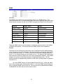
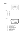
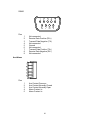
Net I/O N-111 User’s Manual
Revision 8/2/2013
1
WARRANTY INFORMATION
American Fibertek, Inc warrants that at the time of delivery the products delivered will be
free of defects in materials and workmanship. Defective products will be repaired or
replaced at the exclusive option of American Fibertek. A Return Material Authorization
(RMA) number is required to send the products back in case of return. All returns must
be shipped prepaid. This warranty is void if the products have been tampered with. This
warranty shall be construed in accordance with New Jersey law and the courts of New
Jersey shall have exclusive jurisdiction over this contract. EXCEPT FOR THE
FOREGOING
WARRANTY,
THERE
IS
NO
WARRANTY
OF
MERCHANTABILITY OR FITNESS FOR A PARTICULAR PURPOSE OR
OTHERWISE, EXPRESSED OR IMPLIED, WHICH EXTENDS BEYOND THE
WARRANTY SET FORTH IN THIS AGREEMENT. In any event, American
Fibertek will not be responsible or liable for contingent, consequential, or incidental
damages. No agreement or understanding, expressed or implied, except as set forth in this
warranty, will be binding upon American Fibertek unless in writing, signed by a duly
authorized officer of American Fibertek.
© Copyright 2011 American Fibertek, Inc.
2
Table of contents
Introduction ................................................................................................................ 4
Overview
Package Checklist
Product Features
Product Specifications
Getting Started ........................................................................................................... 7
Panel Layout
Connecting the Hardware
LED indicators
Real-time clock
Initial IP configuration.............................................................................................. 13
Factory default IP
Reset sequence
NTP/timeserver configuration
Operating modes...................................................................................................... 17
Overview
Serial Server Mode
Serial Client Mode
Alarm input forwarding
Aux outputs
Pilot interface
Web Interface............................................................................................................ 22
Connecting to the N-111
Interface layout
Operator setup
Global settings
IP Ethernet Setup
NTP Setup
Alarm Setup
Aux Setup
Communications
Watchdog
Upload Firmware
SNMP
Reboot Net I/O
Pinouts and connectors........................................................................................... 36
Power
3
Ethernet
Serial
Aux/Alarm
4
1
Introduction
Overview
Package Checklist
Product Features
Product Specifications
5
Overview
Thank you purchasing your American Fibertek N-111 Net I/O. Please take a few minutes
to read these installation instructions in order to obtain maximum performance from this
product.
The AFI V’NES (Video Network Enterprise Solution) N-111 device allows serial data and
contact closure signals to be made accessible on and linked over a network, with N-111
devices acting as transparent bridges to link together customer equipment. This permits
contact closure signals – such as door opening sensors, alarm buttons, or motion
detectors – to be linked to remote alarm annunciation, or serial data sources such as key
pads or card registers to send data to a remote monitoring system. N-111 devices can
be linked together over a standard Ethernet connection, making it possible to use a preexisting LAN or the Internet for device communication.
Package Checklist
Net I/O
Installation guide
Power cord
Product Features
Serial connectivity over network
Auto-detect 10/100 Ethernet connection
1 port RS232, 485 2W (Half Duplex) or 4W (Full Duplex)
Contact output (Form C, 1500KV isolated)
Alarm input (configurable as NO/NC)
Alarm transmission over network with verification and retry
Product Specifications
LAN
Ethernet
Protection
10/100 Mbps, RJ45
1500KV magnetic isolation
Serial
Serial interface
Duplex
Number of ports
Signals
Baud rate
RS232/RS485
Full or half duplex
1
RS2332:
TXD/RXD, CTS/RTS
RS485:
RX+/-, TX+/0 to 57600 bps
Contact closures
Contact type
Form C
6
Number of contact outputs
Current rating
Voltage rating
1
1A
42VDC
29VAC RMS
Battery backup
Real-time clock
User settings
10 years
Indefinite
Power requirements
Connector type
Power input voltage
Power required
POE class
POE type
Screw terminal
12 VDC
5W maximum
Class 0
802.3af
Mechanical
Dimensions
Weight
Mounting
4.43” x 4.175” x 1.125”
113mm x 106mm x 29mm
8 oz (0.226kg)
Surface mount
Environmental
Storage temperature
Operating temperature
Operating humidity range
-20C to +85C (-4F to 185F)
0C to 70C (32F to 158F)
10 - 95%RH
7
2
Getting Started
Panel Layout
Connecting the Hardware
LED indicators
Real-time clock
8
Panel Layout
N-111 Front
N-111 Rear
Connecting the Hardware
Connecting power
The N-111 has a two position screw terminal which accepts input from an external
12VDC power supply. To connect an external power supply, use two wires, 16-28 AWG
in size. Strip about ¼” of the insulation from the end of the wires before inserting them
into the terminal block. Tighten the terminal screws to secure the wires in the terminal
block. Be sure that the polarity of the applied power is as indicated. Connecting power
with incorrect polarity may damage the N-111.
The N-111 is also capable of being powered over the network connection through
802.3af Power over Ethernet (PoE). To power a N-111 over POE connect one end of an
Ethernet cable to the N-111’s Ethernet port and the other end to a PSE network switch,
midspan injector, or similar device capable of providing power over an Ethernet
connection in accordance with the 802.3af POE standard. When used in this
configuration the DC power input terminal block should not be connected to a power
supply.
Connecting to the network
Connect one end of an Ethernet cable to the N-111’s Ethernet port and the other end of
a cable to the Ethernet network.
9
Connecting a serial device
The N-111 has a DB-9 serial port which can be configured in software for several
different communications modes. The method used to connect to the serial port will
vary depending on the hardware mode selected.
Connecting RS232
To connect the N-111 to a RS232 serial device, connect a serial cable from the serial
port on the rear of the N-111 to the serial device. The N-111 RS232 is configured as a
DTE device.
Connecting RS485 four-wire
To connect to a serial port in RS485 4-wire mode, you will need a DB9 connector wired
as indicated. Four connections will need to be made for the two data transmit lines and
the two data receive lines. Do not make any other connections to any other pins on the
DB9 connector.
Connecting RS485 two-wire
To connect to a serial port in RS485 4-wire mode, you will need a DB9 connector wired
as indicated. Two pairs of pins on the DB9 will need to be bridged together. Two
connections will then need to be made to the bridged pins for the two bidirectional data
lines. Do not make any other connections to any other pins on the DB9 connector.
10
11
Connecting contacts
The N-111 has a port for contact input (alarms) and contact output (aux). This port is a
five pin header with a supplied plug with screw terminals. Customer connections to the
contact port are made by securing stripped wire ends into the screw terminals.
Note: All connections to the screw terminals should be made with the terminal plug
removed from the unit, and with power disconnected from any customer equipment
being connected to the terminals.
Connecting an alarm input
The contact block has two terminals which are used as an alarm/contact input. Viewing
the rear of the N-111, these two terminals are the two on the left side of the contact
block. These terminals are intended to be connected to customer equipment which will
make or break a connection between the two terminals, such as a door open switch or
motion detector contact output. It can be designated through the configuration web page
if an alarm condition will correspond to the connection being made or the connection
being broken.
To connect an alarm source such as a door switch or motion detector to the N-111, use
two wires, 16-28 AWG in size. Strip about ¼” of the insulation from the end of the wires
before inserting them into the terminal block. Tighten the terminal screws to secure the
wires in the terminal block.
Alarm Input Connection
Note: the electrical connection to the alarm inputs are to be connected only to isolated
contact closure devices, and must not be directly connected to any external power or
ground source. Directly connecting either terminal of the alarm input to any voltage
source or external ground may damage the N-111.
Connecting a supervised contact
In supervised contact mode a 1K resistor is connected in series with the contact closure.
This resistor should be located at or close to the contact device, so that short circuits
across the contact lines will be detected. A valid contact closure will be registered only
when the resistance across the contact input lines is measured to be exactly 1K.
12
Connecting an aux output
The contact block has three terminals which are used for the aux contact out function.
(location details). The contact output is a form C contact closure. (terminal details)
To connect an external device to an aux contact out on the N-111, use two wires, 16-28
AWG in size. Strip about ¼” of the insulation from the end of the wires before inserting
them into the terminal blocks. Tighten the terminal screws to secure the wires in the
terminal block.
Aux Contact Out
When an output is not active, the Common terminal will be electrically connected inside
the N-111 to the Normally Closed terminal. When the output becomes active, the
connection between the Common terminal and the Normally Closed terminal will be
broken, and a connection will then be made inside the N-111 between the C terminal
and the Normally Open terminal.
The Aux Output terminals are electrically isolated from the N-111 and from each other,
and can be safely connected to external power sources or grounds.
13
LED indicators
Within 5 seconds of the AC power cable being connected, the N-111 will perform a test
of its front panel indicator LEDs. The LEDS will first light green, then red, then turn off.
Once the sequence has finished the LEDs will resume their normal function and the unit
will be ready for use.
The front panel of the N-111 has several LED indicators. The action of individual LEDS
is as follows:
Power indicator LED
This LED indicates that power is applied to the unit. During initial powering up of the
unit, the power LED will briefly flash green, then red for a moment. It should then light
green and remain green while the unit is on.
Status LED
This LED indicates the status of the aux contact output. During initial powering up of the
unit, this LED will briefly flash green, then red for a moment. It will then be illuminated
green if the aux contact output is active, or off when the aux contact output is not active.
Alarm LED
This LED indicates the status of the alarm input. During initial powering up of the unit,
this LED will briefly flash green, then red for a moment. It will then be illuminated red if
the alarm input is active, or off when the alarm input is not active.
Serial LED
This LED indicates the status of the serial port. During initial powering up of the unit, this
LED will briefly flash green, then red for a moment. During operation, this LED will flash
green when serial data is being transmitted out of the serial port, red when serial data is
being received into the serial port, and off when there is no port activity.
14
3
Initial IP configuration
Factory default IP
Reset sequence
NTP/timeserver configuration
15
Factory default IP
The N-111 is factory programmed with the following default network settings:
IP address
Netmask
Gateway
DNS
192.168.10.11
255.255.255.0
192.168.1.1
None programmed
If the N-111 has not had its IP address changed by the user it will be possible to connect
to it at this network address. If you do not know the IP address of the unit, you can reset
the unit back to factory defaults and then connect at the default address.
16
Reset sequence
If the IP address or username and password to log in are not know, it will be necessary
to reset the N-111 to factory defaults in order to access the administration web interface.
The reset procedure will set all unit settings to their factory defaults.
To reset the N-111 perform the following steps:
Disconnect power from the N-111
With a paperclip or other small object, press and hold the reset button recessed
in the rear of the unit
Connect power to the N-111
Wait for the LED test sequence to complete
Release the reset button
The N-111 will now be reset to factory default configuration. This will reset all userconfigurable settings, including network address, username and password, and all
contact and serial interface settings.
17
NTP/timeserver configuration
The N-111 has a real time clock/calendar which keeps track of the current Coordinated
Universal Time (UTC). This battery-backed time and date setting can be updated by
regular Network Time Protocol (NTP) packets from a server connected to the same
network as the N-111. Alternately, the N-111 can be set to actively connect to a UTC
server for routine clock/calendar updates. The default setting is to accept NTP packets.
18
4
Operating modes
Overview
Serial Server Mode
Serial Client Mode
Alarm input forwarding
Aux outputs
Pilot interface
19
Overview
The N-111 permits devices which use serial or contact closure signals to communicate
with each other to be connected over an Ethernet network. The N-111 acts as a virtual
cable connection, permitting signals to be sent between units as if there was a direct
connection between them. This allows the distance between customer equipment to be
greatly increased, and reduces the number of cables needed to connect multiple pieces
of customer equipment.
The N-111 makes serial ports and contact inputs and outputs accessible on a network.
Other devices on the network (including other VNES devices such as the N-111 or
Commander) can connect to these ports, or accept connections from them, allowing
serial data or contact closure events to be transmitted between devices. The N-111
comes with a configuration web interface which can be used to link serial and contact
ports on multiple N-111 devices together to provide a transparent connection between
customer equipment over the network.
In addition to providing transparent serial or contact connection between customer
equipment, the N-111 is also intended to work as part of a system with V’NES Pilot
software. This permits features such as logging of contact events or serial data.
Configuration of serial links and contacts differ in that serial connections are intended to
be point-to-point communication between to devices, while contacts can be set to trigger
various actions locally or remotely as desired. Each serial port or contact input or output
can be configured independently.
Each serial port can be set to act as either a Server or a Client port.
Serial Server Mode
In Server mode, the N-111 will make available a network port with a unique IP and Port
number. It will then wait passively for an incoming TCP/IP connection to that port.
When a TCP/IP connection is established, data sent to the N-111 through the TCP/IP
connection will be transmitted out on the hardware serial port, and data received on the
hardware serial port will be returned to the TCP/IP connection. This incoming TCP/IP
connection could be a made by another N-111 device in Client mode, another V’NES
product, or by a third-party device.
Data flow between the hardware port and the TCP/IP connection is bidirectional. The
rate at which data on the RS232 port is transmitted and received can be set through the
configuration web page. If the port is configured as an RS232 or 4 wire RS485 data flow
may be full duplex. A port configured as 2 wire RS485 must operate in half duplex,
where data reception will be inhibited while data is being transmitted out by the port.
Once a connection has been made to a port on the N-111, no other connection to that
port will be accepted until the connection is broken. Once the connection is broken the
N-111 will reset and re-open the port, and will wait for the connection to be reestablished.
20
An option is available to only permit incoming TCP/IP connections from a specific
source. If the user specifies an IP address for a server mode port, only connections
from that port will be accepted.
Serial Client Mode
In Serial Client mode, the N-111 will actively attempt to connect to a pre-defined server
device over the network. When a valid IP address and target port are set through the
configuration screen, the N-111 will attempt to open a TCP/IP connection to that
address. Once a connection is made, serial data received on that hardware serial port
will be transmitted to the target server device, and data returned by the target server
device will be returned to the hardware serial port.
Data flow between the hardware port and the TCP/IP connection is bidirectional. The
rate at which data on the RS232 port is transmitted and received can be set through the
configuration web page. If the port is configured as an RS232 or 4 wire RS485 data flow
may be full duplex. A port configured as 2 wire RS485 must operate in half duplex,
where data reception will be inhibited while data is being transmitted out by the port.
Each serial port can only send data to a single target server address at once. If the
connection to the target server is lost, the N-111 will immediately attempt to reconnect.
If the reconnect attempt fails, the N-111 will retry every 60 seconds afterwards to reestablish the connection.
Alarm input forwarding
The N-111 has a contact input which can be connected to customer supplied contact
closure devices such as motion detectors or door switches. This alarm input can be
linked through the N-111 to trigger the aux contact output on that device, or another N111 device or other VNES devices elsewhere on the network.
The conditions which will be considered an alarm can be set through the configuration
web page. Thus the N-111 can be used with alarms where a contact is broken (such as
a wire break or emergency stop switch) or where a contact is made (such as a motion
detector). The minimum duration that the contact must be made or broken before an
alarm is registered can also be set by the user, so that the user can set an alarm to
trigger only if an alarm condition has been present for a certain amount of time.
The aux input may also be configured to operate in ‘supervised’ mode, where the
contact will only be triggered when a 1K resistance is detected across the input. Either
an open circuit or a short circuit will be detected as no contact made. This can be set by
the user through the configuration screen.
When an alarm is triggered, the N-111 can be set to activate aux output contacts either
on that same N-111, or on other N-111 or VNES devices on the network. The user can
set which output to set and whether to turn it on or off in response to the triggered alarm.
The user can also set the target aux contact out to be set on or off for a specific duration
in response to a local alarm condition. Alternately the user can set the target aux
contact out to be set on or off indefinitely in response to a local contact, so that a local
21
contact will cause an aux out to be set or cleared until some other trigger clears or sets
that aux output.
The permitted targets of aux contact actions to be taken in response to local alarms are
any N-111 devices, or any other compatible VNES devices such as C10 Commander
devices, on the same network as the N-111. Up to two independent actions can be
taken by a N-111 in response to a local alarm condition.
Local actions – where a local alarm condition is set to activate an aux contact output on
the same local unit – will be taken immediately. Remote actions – where a local alarm
condition is set to trigger an aux contact on another unit – are stored in a queue and
acted on sequentially. The N-111 will for each queued action attempt to open a
connection to the target device and send it a command to take the set aux output action.
If it fails to connect, or fails to get a confirmation response from the target device, it will
retry the action after a 5 second delay. The N-111 will attempt to take an action 15 times
before abandoning it.
The user may also set up to two messages to be sent to specified IP addresses for each
alarm input. Separate messages can be specified for alarm detection and alarm
clearing.
The N-111 will also send messages to up to four Pilot servers on alarm input change, as
well as periodic updates of all alarm and aux status. These messages can trigger
events in the CMS Pilot Software.
Aux outputs
The N-111 makes an aux contact output available to devices on the network. Any
device on the network can connect to a port on the N-111 and with a properly formatted
and authenticated message signal the N-111 to trigger one of those output ports to
change state. The N-111 will verify that the indicated aux output did in fact change state
and will respond to the device which sent the message to confirm. The N-111’s aux
output can accept state change commands from any number of sources.
The N-111 output is controlled by mechanically latching relays. Once an output has
been commanded to a specific state it will retain that state until commanded otherwise,
even if power to the unit is lost. The user can set through the configuration web page
the behavior for the contacts to take when power applied to the unit after a power
outage. The output can be configured to switch on or switch off. Switching off is the
default condition. The contact will turn off on power loss, this cannot be changed.
The aux output can also be manually controlled by the user through the configuration
web page. The web page will indicate the current state of the aux output and permit the
user to change that state.
The N-111 will also send messages to up to four Pilot servers on aux contact output
change, as well as periodic updates of all alarm and aux status. These messages can
trigger events in the CMS Pilot Software.
Watchdog function
22
The N-111 has a watchdog feature which allows it to monitor the function of a network
connected device. The N-111 can monitor a network device by periodically sending ping
requests to the device over the network. After a number of pings without responses
from the target device, the N-111 takes an action which can be configured by the user.
This action can consist of either setting the aux contact output on the N-111 for a set
period of time, sending a TCP message over the network to a user-defined destination,
or sending an alarm email to a user-supplied address.
This feature permits the N-111 to monitor an external piece of network-connected
equipment, and on detection of a failure trigger an alarm, notify a technician, or powercycle an external device through a relay.
Pilot interface
The N-111 is intended to communicate over the network with up to four Pilot server
devices. The user will provide an address and port number for each of the Pilot servers
he wishes the N-111 to communicate with. The N-111 will automatically attempt to
connect to Pilot servers when a valid IP address and port number have been provided.
Once connected to a Pilot server, the N-111 will send updates of the status of all alarm
inputs and aux outputs to each Pilot server every 5 seconds. It will also send immediate
updates every time an alarm input or aux output changes state. These messages can
trigger events in the Pilot VMS software.
23
5
Web Interface
Connecting to the N-111
Interface layout
Operator setup
Global settings
IP Ethernet Setup
NTP Setup
Alarm Setup
Aux Setup
Communications
Watchdog
Upload Firmware
SNMP
Reboot Net I/O
24
Connecting to the N-111
Use a Windows PC or similar computer connected to an Ethernet network. Connect the
N-111 to the same network. Ensure that the network is one where the IP address of the
N-111 (Default address is 192.168.10.11) is legal and not already in use.
You will need to use a browser program such as Internet Explorer with cookie
functionality enabled to connect to the N-111.
Type 192.168.10.11 in to the Address bar of your browser window and then press Enter.
(If you have changed the IP address of the N-111, you will need to type that address in
instead.) You should see a prompt for a User Name and Password to access the unit.
[note – need to fix this to have the right address and username/password]
The default User Name and Password are “Admin” and “Password” respectively. It is
strongly recommended that you change these when you first install and set up your unit.
Interface layout
The N-111 web interface screens use a common design in which the screen is divided
into three sections. Across the top of the screen is a title bar which contains the usersettable device name and device location strings, and the current time and date setting.
Down the left side of each screen is a menu used to access the configuration sub-pages.
Clicking on one of the selections in that menu will bring up that configuration sub-page.
The name of currently selected sub-page will be indicated in bold.
25
When an individual sub-page has been selected, that sub-page will display in the main
part of the interface screen. The name of that sub-page will be shown in a header just
below the main title bar. Controls specific to each sub-page will be shown below that,
and at the bottom of the screen will be buttons labeled “Save” and “Default”
The Save button at the bottom of each screen will cause the specific settings on that
screen to be saved to the N-111’s nonvolatile configuration files, and then will return the
user to the main configuration screen.
The Default button will cause all settings on that screen to be reset back to their factory
defaults. It will also save the default settings to the nonvolatile configuration memory
and return the user to the main configuration screen. These changes will take place
immediately.
26
Operator setup
The Operator Setup screen permits the user to set the Username and Password used to
log in to the operator web page. A username and password combination are required. It
is recommended that you change these from the default settings.
Setting
Default Value
Range
Username
"Admin"
15 characters
Password
"Password"
15 characters
Changes to this page take place immediately. If you change the username or password
and save changes, you will then have to enter the new username and password to
continue using the web interface.
27
Global settings
The Global Settings screen permit the user to change the Device Name and Device
Location strings associated with the N-111. These strings are shown at the header at
the top of every configuration web page. They are also provided in the configuration
data sent to any Pilot server which the N-111 communicates with to identify the N-111.
The user may optionally enter contact information for this unit. This string is used as
part of the unit identification information during SNMP reporting. It is also included as
part of the configuration data set to Pilot servers.
The Global Settings screen also permits the user to change which authentication will be
used for the API. The user may select for the fixed internal username and password to
be used, or for the user-supplied username and password to be used.
Setting
Default Value
Range
Device Name
"N-111"
39 characters
Device Location
Contact Information
API Authentication
"Afi"
39 characters
39 characters
Internal Authentication
User Authentication
Internal
Authentication
Changes to the Device Name and Device Location settings take effect immediately.
Changes to the API Authentication will take effect at the next unit startup. Note that
when tunneling contacts between units, both units must have the same API
Authentication setting and the same Username and Password set.
28
IP Ethernet Setup
The IP Ethernet Setup page permits the user to set the network address and network
access settings of the N-111. It also permits the user to designate up to four Pilot
servers for the N-111 to connect and sent configuration data and status updates to.
Setting
IP Address
Subnet Mask
Default Gateway
DNS
MAC address
Default Value
"192.168.10.11"
"255.255.255.0"
"192.168.10.1"
“0.0.0.0”
Unique for each unit
Range
15 characters
15 characters
15 characters
15 characters
6 bytes hexadecimal
These four IP configuration strings must be provided in dotted-quad format and have a
maximum length of 15 characters. Note that changes to these settings take place
immediately, so if you change the unit’s IP address in this screen and then save the
settings you will have to enter the new IP address in the browser address bar to
reconnect to the unit. Changes to the IP address or subnet mask will also cause any
active Pilot or serial port network connections to disconnect. Those connections will
then attempt to reconnect with the new network settings.
The DNS is an optional field. If a valid DNS address is provided, it will be used to look
up the address of the mail server provided by the user.
Setting
Pilot Server
IP
Port
Default Value
1-4
"0.0.0.0"
8800
29
Range
Fixed
15 characters
8000 - 32767
Settings for four Pilot servers are provided. Default settings for each are “0.0.0.0” and
port “8800”. An N-111 will not attempt to connect to a Pilot server whose address is still
“0.0.0.0”, but will begin attempting to connect as soon as a valid address is entered and
saved.
For each of the four target servers, an indication of “CONNECTED” or “NOT
CONNECTED” is provided to show if the N-111 has successfully connected to that
server.
Setting
To address
SMTP Mail server
Login name
Password
Retries
Default Value
3 tries every 15 minutes
Range
80 characters
64 characters
64 characters
16 characters
0-999, 0-999
In order to send email notifications the N-111 needs to connect to an SMTP mail server.
The server may be an IP Address or mail server URL. In the case of a URL, at least one
DNS server must be specified on the IP Ethernet set up page.
A ‘Mail status’ indication is provided to indicate the status of any attempt to send an
Email message.
30
NTP Setup
The NTP Setup screen is used to control how the real-time clock/calendar of the N-111
is updated. The user can select one of three update modes: No updates, NTP
broadcast updates, or polling a NTP server.
If “None” is selected for the NTP update mode, the N-111 will never update its real-time
clock/calendar. If the time was set accurately before updating was disabled and a
working battery is installed it should retain a fairly accurate time and date for some time.
There will be some drift from true time and date over time, so this mode is not
recommended.
If “Accept NTP Broadcast” is selected, the N-111 will update its time and date settings
every time it received a NTP broadcast packet on the network. This is the default
setting.
If “Poll NTP Server” is selected, the N-111 will periodically connect to a NTP server to
update its RTC setting. No server is specified by default, so if the user wishes to use
this function they will have to specify a server address. The time between updates can
be set. The default setting for update rate is to update once every 12 hours.
Setting
Default Value
Range
Mode
Accept NTP Broadcast
Server Address
Hours
Minutes
"0.0.0.0"
12
0
None
Accept NTP Broadcast
Poll NTP Server
15 characters
0 - 32767
0 - 59
31
Alarm Setup
The Alarm Setup screen is used to configure the N-111’s alarm input, and the actions to
be taken when the input is triggered. The hardware alarm contact inputs can have its
trigger conditions and actions independently configured.
Alarm settings
Setting
Default Value
Range
Name
Input Type
“alarm-N”
Normally Open
Supervision
Normal
Duration
1 second
15 characters
Normally Open
Normally Closed
Normal
Supervised
Static
1,5,15,30,or 45 seconds
1 or 5 minutes
The alarm input has an associated user-settable text label. The alarm name label is
supplied along with the number when reporting the status of an alarm input to a Pilot
server. This label may be up to 15 characters long.
The Input Type setting selects if the normal (non-alarm) state is if the contact input is
closed or if the contact input is open. In Normally Open mode an alarm will be
registered when the two contact input terminals are shorted to each other. In Normally
Closed mode an alarm will be registered when the two contact inputs are not shorted to
each other. The default mode is Normally Open.
The Supervision setting selects if the alarm input is a normal contact closure or a
supervised contact closure. In supervised mode the contact closure will only be
registered if a 1K resistance value is measured across the alarm input terminals. An
open circuit and a short circuit will both be detected as no contact closure. The default
mode for Supervision is Normal (non-supervised) contact mode.
The duration setting sets a minimum time for which the alarm condition must be
maintained before an alarm is triggered. Setting the duration to “Static” will cause the N111 to trigger an alarm the moment it detects an alarm condition. If a longer duration is
32
selected the N-111 will not trigger an alarm until the input has been maintained
continuously for that duration.
33
Alarm actions
The alarm input can have set multiple actions to be taken on that alarm’s triggering.
These actions consist of setting the contact outputs on that same N-111, or on other N111 devices or other VNES devices on the network, of sending specific text messages to
a target over the network, or of sending an email message.
Alarm settings
Setting
Email
SNMP
Default Value
Off
On
Range
Check box on/off
Check box on/off
Each alarm input can be configured to send an email message when the associated
alarm input changes state. Multiple alarm inputs which occur within 5 seconds will be
combined and sent as separate lines in a single email. Each event line in the email
contains a time stamp indicating when that event occurred, and the entire email will also
include information on the name and location of the N-111 which sent the email.
If the unit is configured to send trap messages to a SNMP server, then a change of state
on each alarm will trigger the sending of an appropriate trap message. This feature can
be individually enabled or disabled for each alarm input.
Remote Aux Actions
Setting
Default Value
Range
Action address
Action aux
Action state
“0.0.0.0”
1-6
On
Action duration
5 seconds
15 characters
1-99
On
Off
Follow
1,5,15,30,or 45 seconds
1 or 5 minutes
Indefinitely
Address indicated the network IP address of the target device. This may be up to 15
characters long and must be in dotted-quad format. The default setting of “0.0.0.0”
indicates no action to be taken. Set this to the IP address of this N-111 to indication an
action to be taken on the local unit. Setting it to another valid IP address will cause the
N-111 to attempt to connect to that target on the network and set an output on it when
the alarm is triggered.
Aux is the number of the aux contact out on the target device to trigger. The valid range
of this number depends on the device being contacted. The N-111 does not know what
the target unit is, so it is the responsibility of the user to select a valid output number for
the target device.
34
Action selects if the target aux output is to be set ON or OFF in response to the local
alarm condition.
Duration sets how long to set the target output for. If a duration is set, the N-111 will set
the target aux contact out to the selected status (ON or OFF) for the chosen duration,
and them will set the target to the opposite setting. Thus, if an alarm is set to trigger a
certain aux ON for 5 seconds, the N-111 will when that alarm is triggered contact the
target unit, set the indicated aux to ON, wait five seconds, and then set the indicated aux
to OFF.
Selecting “Follow” for the duration will cause the N-111 to make the targeted aux contact
out follow the state of the alarm input. If the action selected is ON, the target will be
turned ON whenever the local alarm goes ON, and OFF when the local alarm goes OFF.
Selecting an action of OFF will invert the behavior, causing the targeted aux to go OFF
when the local alarm is triggered and ON when it is not.
Selecting “Indefinitely” for the duration will simply cause the N-111 to set the target aux
contact ON or OFF once and leave it so set.
Buttons are provided which force an ON or OFF message to be sent to the indicated
remote aux output immediately. These are used to test unit configuration and network
connectivity.
IP Message Actions
Setting
Default Value
Range
IP:PORT
“0.0.0.0:23”
24 characters
Message – Alarm
80 characters
Message – Clear
80 characters
Address indicates the network IP address and port of the target device. This may be up
to 24 characters long and must consist of an IP address in dotted-quad format, followed
by a colon, followed by a port number in the range of 0 to 32767. The default setting of
“0.0.0.0:23” indicates no action to be taken.
Message – Alarm holds a text message of up to 80 characters. When the local alarm is
triggered this message will be sent to the entered IP address. A ‘test’ button is provided
so that the user may manually test the sending of this message.
Message – Clear holds a text message of up to 80 characters. When the local alarm is
cleared this message will be sent to the entered IP address. A ‘test’ button is provided
so that the user may manually test the sending of this message.
35
Local Aux Actions
Setting
Default Value
Range
Local aux
Action state
1-6
On
Action duration
5 seconds
1-6
On
Off
Follow
1,5,15,30,or 45 seconds
1 or 5 minutes
Indefinitely
Aux is the number of the aux contact out on the local device to trigger. This number may
be from 1 to 6.
Action selects if the target aux output is to be set ON or OFF in response to the local
alarm condition.
Duration sets how long to set the target output for. If duration is set, the N-111 will set
the target aux contact out to the selected status (ON or OFF) for the chosen duration,
and then will set the target to the opposite setting. Thus, if an alarm is set to trigger a
certain aux ON for 5 seconds, the N-111 will when that alarm is triggered contact the
target unit, set the indicated aux to ON, wait five seconds, and then set the indicated aux
to OFF.
Selecting “Follow” for the duration will cause the N-111 to make the targeted aux contact
out follow the state of the alarm input. If the action selected is ON, the target will be
turned ON whenever the local alarm goes ON, and OFF when the local alarm goes OFF.
Selecting an action of OFF will invert the behavior, causing the targeted aux to go OFF
when the local alarm is triggered and ON when it is not.
Selecting “Indefinitely” for the duration will simply cause the N-111 to set the target aux
contact ON or OFF once and leave it so set.
Timing of actions on remote units
Actions to set aux contact outputs on the local unit will be acted on immediately. Actions
to set aux contact outputs on other units on the network, or to send text messages to
other units on the network, may be delayed up to a few seconds according to network
conditions.
The N-111 stores actions to be taken in a queue. Each action is attempted in turn, and if
an action is unable to be completed (unable to reach target address or target device did
not acknowledge the command) it is pushed back on the queue and re-attempted after 5
seconds. After 15 failed attempts an action will be abandoned.
The N-111 is capable of attempting 6 remote actions simultaneously, so a long wait for a
target to respond will not prevent other actions from being attempted.
36
When a action is taken to set a target aux out for a specific time duration, the beginning
of that duration will be from when the N-111 first succeeded in contacting the target unit,
not from when the alarm was triggered. Thus if a N-111 is set to set a specific aux
contact out ON for 5 seconds when an alarm input is triggered, and it takes 3 seconds to
initially contact the target, the N-111 will turn the target OFF 5 seconds after turning it
ON and therefore 8 seconds after the alarm.
37
Aux Setup
The Aux Setup screen is used to configure the N-111’s aux contact output.
Setting
Default Value
Range
Name
Email
“aux-N”
Off
15 characters
On/Off checkbox
SNMP
State on Startup
On
Off
Current state
N/A
On/Off checkbox
Off
On
On
Off
The aux out also has a user-settable text label which may be up to 15 characters long.
The aux name label is supplied along with the number when reporting the status of an
aux contact output to a Pilot server.
The aux contact can be configured to send an email message when it changes state.
Multiple aux changes which occur within 5 seconds will be combined and sent as
separate lines in a single email. Each event line in the email contains a time stamp
indicating when that event occurred, and the entire email will also include information on
the name and location of the N-TAH which sent the email.
If the unit is configured to send trap messages to a SNMP server, then a change of state
on the aux will trigger the sending of an appropriate trap message. This feature can be
individually enabled or disabled for the aux contact.
As each contact output has terminals for normally closed and normally open, there is no
setting to change the action of a contact in software.
The default behavior of the N-111 is set the output contact OFF when power is applied.
Optionally, the user can select for the relay to turn ON when power is first applied.
The Aux Setup screen indicates the current state of the aux output, showing it as ON or
OFF. These indications are updated every few seconds. Buttons are provided for each
state so that the user may manually switch the output ON or OFF through the setup
screen.
The aux contacts automatically accept commands from other devices on the network,
such as other N-111 devices, Scout or Commander devices, or other Pilot servers. This
function cannot be disabled.
38
Communications
The Communications screen allows the user to configure the N-111’s serial port.
Setting
Default Value
Range
Name
Mode
“aux-N”
RS232 Server
Speed
IP
57600
“0.0.0.0”
15 characters
Disabled
RS232 Server
RS485-4 Wire Server
RS485-2 Wire Server
RS232 Client
RS485-4 Wire Client
RS485-2 Wire Client
0-57600
15 characters
Port
Flow Control
1-4
Hardware
1-4
Hardware
None
The serial port has a user-settable text label identifying it for user documentation
purposes. This string can be up to 15 characters long.
The serial mode drop-down menu allows the user to select both the hardware interface
and the software behavior of the serial port. The hardware mode of the port can be
selected between RS232, RS485 in 4 wire mode, and RS485 in 2 wire mode, to control
the hardware behavior of the serial output pins. RS232 mode ports can be connected to
customer equipment with any standard serial cable. RS485 2 wire or 4 wire ports will
need to use a custom header to connect to customer equipment.
The software mode can be selected from server or client mode. “Disabled” mode can be
selected to leave a port with no connection to the network.
The hardware baud rate for each port can be selected from 0 to 57600 bps. This
controls the rate at which the hardware port receives and transmits data. It does not
affect the rate at which information is transmitted over the network.
IP address specifies the address of the target N-111 on which there will be a port which
this serial port is to link to. This address may be up to 15 characters long and must be in
dotted-quad format. An IP address is required for client mode and must contain the
network IP address of the device the client will connect to. In server mode the IP
address is optional. If an IP address is provided in server mode the server port will only
accept incoming connections from that address.
39
The port number indicates which port on the target device the N-111 will attempt to
connect to in client mode. Note that these numbers refer to the number of the serial port
as indicated on the device and web screen, not the IP port number. This number has no
function in server mode.
The flow control setting is used to control the function of the CTS/RTS pins when the
port is configured in RS232 mode. With flow control set to ‘Hardware’ the RTS output
pin on each port will only be asserted when that port is connected to a destination that
can receive data, and the port will only transmit data when the CTS input pin is asserted.
With flow control set to ‘None’, the RTS pin will be asserted all the time and the CTS
input pin will be ignored.
Procedure to link serial ports on two Net I/O devices together
The serial port function of the N-111 is intended to be used with two or more N-111
devices on a network, where a serial port on one N-111 is linked to a serial port on
another N-111. The only restriction is that client and server ports must be linked
together in one-to-one pairings.
To link serial ports on two N-111 devices, you must designate the port on one device as
the Slave, and one port on the other device as the Client. The Client port must be
configured with the IP address of the Server, and the port number of the port on the
server being connected to. The Server port may either be configured with the IP
address of the Client, or set to ‘0.0.0.0’.
It is recommended that both ports in a client-server pair be set to the same hardware
mode and the same baud rate. Setting different baud rates between the two ports is
permissible, but not recommended as characters may be dropped if data is coming in to
the higher speed port faster than they can be transmitted out of the lower speed port.
40
Baud rate and buffer size concerns
Each port has a buffer which stores data coming in from the serial port and stores it until
it can be transmitted over the network. Normally this data is sent out over the TCP/IP
connection as quickly as it is received. During conditions of heavy network activity or
high latency the buffer may become full. When this occurs some data may be lost.
Data coming from the remote unit over the TCP/TP connection will be sent out over the
local serial connection at the specified baud rate. If the remote unit is sending data at a
higher rate than the local baud rate permits transmission, data may be lost.
41
Watchdog
The N-111 has a watchdog function which can be used to monitor a networkconnected device for failure, and perform user-configurable actions when that device
fails to respond.
Setting
Default Value
Range
Enabled
Not Enabled
Ping IP Address
Interval
Timeout
0.0.0.0
15 seconds
3 seconds
Enabled
Not Enabled
15 characters
1-9999 seconds
1-9999 seconds
Failures
Restart Delay
3
5 minutes
1-9999
1-9999 minutes
When the Watchdog feature is enabled, the N-111 will send ping requests to the
target IP address at a frequency determined by the Interval setting. The N-111 will wait
for a period of time determined by the Timeout setting for a response to each ping
message. If it does not receive a ping response for a ping, it will increment a counter
which records the number of consecutive failed pings. A single successfully received
ping response will set this counter to zero. When a number of failed ping responses
equal to the Failures setting has occurred, the unit will take some action as determined
by user settings. It will then wait for a number of minutes determined by the Restart
Delay setting before sending any more ping messages.
42
Watchdog failure actions
Setting
Default Value
Range
Aux time
15 seconds
1-9999 seconds
TCP Message
IP:PORT
40 characters
“0.0.0.0:23”
24 characters
Email Message
80 characters
When the N-111 fails to receive a number of consecutive pings from the target
device, it will trigger the AUX contact output for a time period determined by the Aux
Time setting. This output is intended to be used to trigger an alarm buzzer or light, or to
cycle power on a small DC-powered device. The contact is rated for 42 volts, up to 1
Amp current, and should not be used to switch line voltage or any device which draws
more than 1 Amp.
The N-111 can also optionally send a TCP message of up to 40 characters to a
target address on the network. IP:PORT indicates the network IP address and port of
the target device. This may be up to 24 characters long and must consist of an IP
address in dotted-quad format, followed by a colon, followed by a port number in the
range of 0 to 32767. The default setting of “0.0.0.0:23” indicates no action to be taken.
The TCP Message field holds a text message of up to 40 characters. When a
ping response occurs, this message will be sent to the specified network address.
The Email Message field holds a text message up to 80 characters long which
will be sent to the email address specified in the IP Ethernet Setup screen. If a message
is specified here, it will be sent to this address when a watchdog failure occurs.
The Test Restart button is used to manually trigger a Watchdog reset. This will
trigger the aux output to occur, and if specified will trigger a TCP message to be sent
and an Email notification to be sent.
43
Upload Firmware
The Upload Firmware page is used to update the firmware in the N-111 in the
field, without having to open the unit or return it to American Fibertek. This feature is
only to be used to upload firmware binaries supplied by AFI.
To use the feature click on the ‘Browse…’ button. A dialog box will open
requesting the file to upload. Navigate to the binary file provided by AFI and open it.
The dialog box will close, and the name of the selected binary file will appear in the text
box. Press the ‘Upload’ button to start uploading the new binary file.
The file upload may take up to a minute to complete. Once it has competed you
should see either a screen indicating that the firmware file was uploaded properly, or that
some error occurred and the N-111 was unable to use the uploaded firmware file.
To complete the firmware upload process and begin using the new firmware, you must
power-cycle the N-111. Rebooting the unit with the Reboot Net I/O function will not be
sufficient to finish updating the firmware. The unit must be turned off, let to sit for at
least 5 seconds with no power, and then turned back on.
44
SNMP
The SNMP screen allows the user to configure the N-111’s SNMP function. This
function allows the N-111 to automatically share information regarding the state of alarm
inputs and aux contacts with the user’s SNMP management software over the network.
Setting
Default Value
Range
SNMP Enable
Get Community
Set Community
Set Enable
Enabled
public
private
Enabled
Enable/Disable
39 characters
39 characters
Enable/Disable
SNMP Server 1
0.0.0.0
15 characters
SNMP Server 2
0.0.0.0
15 characters
SNMP Server 3
0.0.0.0
15 characters
SNMP Server 4
0.0.0.0
15 characters
The entire SNMP function can be enabled or disabled by selecting either of the Enable
or Disable radio buttons. This causes the entire SNMP function to be enabled or
disabled.
The names of the Get and Set communities can be changed from their default settings
to any text string of up to 39 characters. The Get community is used when retrieving the
current values from the N-111. The Set community is used when changing values on
the N-111, for example turning an aux contact on or off. The names of the communities
must mach the community names set in the user’s management software. This enables
a degree of security for controlling contacts or changing warning levels. The Set
function can also be independently disabled, so that it will only be possible to read data
from the N-111.
Up to four SNMP servers can be programmed into the N-111. When the alarm
input or aux contact output changes state, the N-111 will send SNMP trap messages to
every configured SNMP server on the list. This function can be independently enabled
or disabled for the alarm input and aux contact output.
45
Reboot Net I/O
The Reboot Net I/O screen allows the user to perform a hardware reset of the N-111.
This will not affect the state of the stored configuration files, but will cause all N-111
systems to reset as if a power interruption had occurred. A single button, “Click here to
reboot”, is provided to restart the system.
The N-111 takes approximately 10 seconds to reboot and return to full function after this
function is used.
When the N-111 is being reset, the aux contact output turn OFF until the reset cycle is
completed, at which time it will behave as configured on the ‘Aux Setup’ page. Any
messages to change aux outputs from other devices on the network will be ignored while
the device is rebooting. Alarm conditions on the alarm input terminal will also be ignored
while the device is rebooting.
When the N-111 is rebooting, all serial data links over the network will be dropped. The
unit will attempt to reestablish them once it has finished rebooting, but any data arriving
on the serial ports during the reboot cycle will be lost.
46
A
Pinouts and connectors
Power
Ethernet
Serial
Aux/Alarm
47
Ethernet
Pins
1
2
3
4
5
6
7
8
TX+
TXRX+
N/C
N/C
RXN/C
N/C
Serial
RS232
Pins
1
2
3
4
5
6
7
8
9
Data Carrier Detect (DCD)
Receive Data (RD)
Transmit Data (TD)
Data Terminal Ready (DTR)
Ground
Data Set Ready (DSR)
Request To Send (RTS)
Clear To Send (CTS)
Not connected
48
RS485
Pins
1
2
3
4
5
6
7
8
9
Not connected
Receive Data Positive (RX+)
Transmit Data Negative (TX-)
Not connected
Ground
Not connected
Transmit Data Positive (TX+)
Receive Data Negative (RX-)
Not connected
1
2
3
4
5
Aux Contact Common
Aux Contact Normally Closed
Aux Contact Normally Open
Alarm Contact In
Alarm Contact In
Aux/Alarm
Pins
49
B
Service Information
Technical Assistance
If any questions arise concerning the installation of American Fibertek products, please
allow us to assist you by calling, faxing or by E-mail.
Phone: + 732 302 0660
FAX: + 732 302 0667
[email protected]
50
51