1
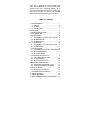
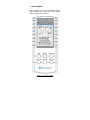
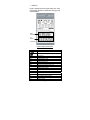
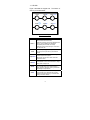
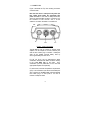
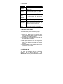
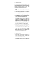
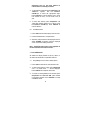
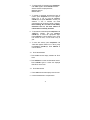
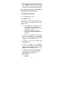
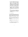
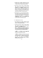
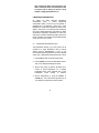
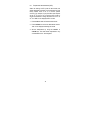
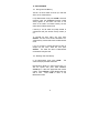
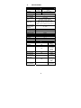
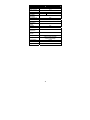
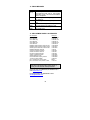
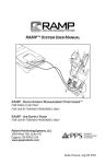
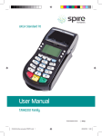
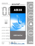
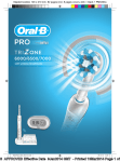
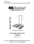
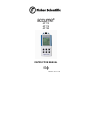
®
AP 110
AP 115
AP 125
INSTRUCTION MANUAL
68X452201 Rev. A 07/08
Thank you for selecting an accumet portable (AP)
meter. This portable meter is a microprocessor-based
instrument with many user-friendly features, all of
which are accessible through the keypad. Please read
this manual thoroughly as well as your separate
electrode manual before operating your instrument.
TABLE OF CONTENTS
1. THE INSTRUMENT................................................ 1
1.1 DISPLAY .......................................................... 2
1.2. KEYPAD.......................................................... 3
1.3 CONNECTORS................................................ 4
2. FEATURES ............................................................ 5
3. BATTERY INSTALLATION .................................... 5
4. ELECTRODE USE ................................................. 5
5. pH OPERATION..................................................... 6
5.1 Using setup in pH mode to select options ...... 6
5.2 pH Standardization.......................................... 8
5.3 pH Measurement............................................. 8
6. mV OPERATION .................................................... 9
6.1 Using setup in mV mode to select options ..... 9
6.2 mV Measurement.......................................... 10
7. R.mV OPERATION .............................................. 10
7.1 Using setup in R.mV mode to select options 10
7.2 R.mV Standardization ................................... 11
7.3 R.mV Measurement ...................................... 11
8. ION OPERATION (AP125 only) ........................... 12
8.1 Using setup in the Ion mode......................... 12
8.2 Ion Standardization ....................................... 13
8.3 Measurement in Ion mode ............................ 14
9. MEASURING TEMPERATURE............................. 15
9.1 Temperature Standardization (ATC) ............. 15
9.2 Temperature Standardization (MTC) ............ 16
10. DATA STORAGE ............................................... 17
10.1 Storing Value into Memory............................ 17
10.2 Recalling Value from Memory ....................... 17
11. SPECIFICATIONS .............................................. 18
12. ERROR MESSAGES ......................................... 20
13. REPLACEMENT PARTS & ACCESSORIES ..... 20
1. THE INSTRUMENT
Before operating the meter, please familiarize yourself
with the location and function of its various display
elements, keypad and connectors.
Figure 1 Front view of meter
1
1.1 DISPLAY
Figure 2 illustrates the liquid crystal display area. Each
of the display elements is referenced in the figure and
described below.
Meter
Prompts
pH
Buffers
Ion
Standards
Figure 2 Display annunciators
SYMBOL
DESCRIPTION
Battery indicator with scale
Meter operating with optional AC power supply
Setup
View
Std
Meas
pH
R.
mV
ION
STABLE
EFF%
Clear
AUTO
MM/DD/YY
0
C
ATC
mV
Set Up mode
View data stored in memory
In Standardization mode
In Measurement mode
pH Measurement mode
Relative millivolt Measurement mode
Absolute millivolt Measurement mode
Ion Measurement mode
Reading stability indicator
Slope efficiency in percentage
Clear (erase) data
Auto-read function ON
Month/Date/Year
Temperature in Degrees Celsius
Automatic Temperature Compensation
Offset in millivolts
2
1.2. KEYPAD
Figure 3 illustrates the keypad area. The function of
each key is described below.
mode
save/▲
setup/meas
on/off/
view/ ▼
std/enter
Figure 3 Meter Keypad
KEY
on/off/ ☼
DESCRIPTION
Press to turn the meter ON. The meter will default to
the last measurement mode used.
When ON, press this key to turn the backlight ON or
OFF (to conserve batteries, the backlight is
automatically turned off after 30 seconds).
When ON, press and hold this key for 3 seconds to
turn the meter OFF.
mode
Press this key to toggle between pH, mV, Relative
mV (R.mV) and Ion (AP125 only) measurement
modes.
setup/meas
Press this key to enter Setup menu. Press again to
scroll through the Setup options.
Measure key also serves to refresh value when
Auto-Hold is active.
std/enter
Press this key to activate and confirm the
standardization. Also to confirm selection or change
being made in Setup mode.
save/▲
Press this key to store measured data into memory
(up to 200 data sets). Also to increase value or
make selection in the Setup mode e.g. for date and
time setting scroll up selection.
view/▼
Press this key to recall and select memory location
of stored data. Also to decrease value or make
selection in the Setup mode e.g. for date and time
setting scroll down selection.
3
1.3 CONNECTORS
Figure 4 illustrates the Top View showing connectors
of the AP meter.
Note that the meter is waterproof only when the
blue rubber plugs and/or the appropriate ATC
probe are used. If the meter is totally submersed,
water may enter the BNC connector. If necessary, dry
the connector to avoid corrosion. Also, If an AC
adapter is connected, the meter is not waterproof.
TOP
AC
BNC
ATC
Figure 4 View of Connectors
The AC jack is used to connect an optional power
adapter. If an AC adapter is not used, Seal the jack
with the blue rubber plug to maintain a waterproof
state. An AC adapter prevents battery drain by
removing the battery from the circuit.
For pH, mV, R.mV, and Ion measurement, attach
combination electrodes with BNC connectors directly
to the middle BNC jack on the meter. Noncombination (half cell) electrodes can be used with
appropriate adapters sold separately.
For best results, automatic temperature compensation
(ATC) is recommended. Insert the accumet waterproof
ATC connector into the ATC jack. Insert the attached
blue rubber plug if an ATC probe is not used to
maintain a waterproof state.
4
2. FEATURES
FEATURE
Display
Resolution
DESCRIPTION
Operator-selectable using setup/meas key,
choose 8888.8 for 0.1, 888.88 for 0.01,
88.888 for 0.001
Auto Read
When enabled, display locks on current value
when stable indicator appears. Press meas
key to unlock and resume reading
Battery
Saver
Backlight
When enabled, meter automatically turns off
after 20 minutes of inactivity
To conserve battery life, the backlight
automatically turns OFF after 30 seconds
Slope
Display
View electrode slope and mV offset for
current reading with setup/meas key
Auto-buffer
Recognition
Meter selects from 5 (USA or NIST) or 6
(EURO) pre-programmed standards with
temperature correction of buffer value
Standardization
User selectable 1-5 cal points for USA/NIST
or 1-6 cal points for EURO standardization.
3. BATTERY INSTALLATION
To install the battery, perform the following steps:
1. Remove the battery cover by loosening the 3
screws that hold the battery cover at the back of
the meter using a Phillips screwdriver.
2. Disconnect the old 9V battery and install new one
into meter battery compartment.
3. Make certain the battery wires are positioned so
that they do not interfere with the closing of the
battery cover. Battery cover edges may damage
the wires.
4. Replace the battery cover and tighten the 3 screws
to secure the cover in place.
4. ELECTRODE USE
This meter can be directly fitted with combination
electrodes, with or without built-in ATC.
See
Accessories section for pH/ATC electrodes as well as
adapters for use with half cells.
5
1. Condition your electrode by soaking as needed in
electrode storage solution, pH 4 or 7 buffer, or KCl
solution. Complete hydration can take anywhere
from minutes to overnight for very dry electrodes.
2. Twist the metal shorting cap to remove it from the
BNC jack of the meter. Install your electrode by
twisting it to lock it in place. The shorting cap is
designed to hang freely when the BNC jack is
occupied.
3. Rinse the electrode using clean water and gently
shake dry between measurements. Store in
electrode storage solution, pH 4, pH 7, or KCl
solution. If refillable, keep the fill hole open during
measurement but close for longer periods of nonuse and storage. Refill when the level of fill solution
recedes below the manufacturer’s recommended
level.
Refer to the manufacturer’s electrode instruction
manual for specific details on electrode use.
5. pH OPERATION
5.1 Using setup in pH mode to select options
From the pH Measure screen:
The setup button is a scroll button which allows you to
view and change several operating parameters. While
in setup you may:
•
•
•
Press mode to return to the Measure screen
without making a change or selection
Press setup and scroll through the operating
parameters in the meter
Press enter to accept the parameter as
displayed or to accept a change made to that
parameter and return to the measurement
mode.
1. To activate or de-activate the AUTO hold read
function press setup/meas once. Select AUTO
6
HOLd ‘Yes’ or ‘No’ by using the save/▲or
view/▼keys. Press std/enter to accept.
2. To display the % slope efficiency ‘EFF%’ and mV
offset ‘mV’ press setup/meas twice.
3. To erase an existing pH standardization/
calibration press setup/meas until ‘Clear buf std’
(Clear buffer standard) appears on the screen.
Press std/enter to accept or mode to cancel.
4. To change the buffer standard group, press
setup/meas until ‘bUF USA’ appears. Press
std/enter accept the desired group (USA, NIST, or
EURO) when it is displayed.
5. To change the pH resolution press setup/meas
until ‘88888’ appears. Press std/enter when the
desired resolution is displayed below;
88.888 to select 0.001 (AP115 & AP125 only)
888.88 to select 0.01
8888.8 to select 0.1
6. To activate or deactivate the Automatic Shut off
function press setup/meas until ‘A.Off’ appears.
Select ‘Yes’ or ‘No’ by using the save/▲or
view/▼keys and press std/enter to confirm your
selection. If ‘Yes’ is selected, the meter
automatically turns off after 20 minutes of inactivity.
Note: Selecting ‘No’ can result in total battery
exhaustion—once on, the meter remains on
until the meter is manually turned off.
7. To set meter time and date press setup/meas until
‘MM/DD/YY’ appears. Use the save/▲or
view/▼keys to select the appropriate digits.
Press std/enter to confirm selection and to move
from minutes to hours; or from month to day to
year.
8. To clear data memory press setup/meas until
‘Clear dAtA’ appears. Select ‘Yes’ or ‘No’ by using
the save/▲or view/▼keys. Press std/enter to
confirm selection.
7
5.2 pH Standardization
For best results, standardizing (calibrating) your meter/
electrode system against certified accurate solutions is
strongly recommended due to electrode variations and
changes in electrode response over time. Daily
standardization with fresh buffers is common.
1. Press mode until the display indicates the pH
mode.
2. Immerse the rinsed electrode(s) into a buffer from
the chosen group (USA, NIST or EURO). Stir
moderately if possible. Buffers can be used in any
order, however neutral (pH 7) is ideally first.
3. Press std/enter to access the Standardize screen.
‘Std’ is now displayed indicating this mode.
4. Allow the pH value to reach a constant reading
(little variation over 30 seconds as well as the
appearance of the STABLE annunciator). Press
std/enter again to complete standardization of the
value. The meter automatically recognizes the
buffer and returns to the Measure mode.
Successfully standardized buffer values remain on
the display until cleared—even after power off.
5. Repeat steps (2) to (4) with subsequent buffers.
The meter will briefly display ‘EFF%’ (efficiency as
% slope) before returning to the Measure mode.
If this value is not between 70-120%, ‘SLOPE
Error’ (Electrode error) is displayed. The
standardization value is not accepted and the
instrument returns to the Measure mode.
5.3 pH Measurement
1. Press mode until the display indicates the pH
mode. Immerse the electrode(s) into the sample
solution. Stir moderately if possible.
2. Allow the pH value to reach a constant reading
(little variation over 30 seconds as well as the
8
appearance of the STABLE annunciator). The pH
reading may be recorded at this time.
a. If AUTO is not displayed, the auto read hold
function is not active, and the meter will
continuously monitor the live pH value.
b. If AUTO is displayed, the meter will lock the
measured value on the screen when the
STABLE annunciator appears. To release the
locked value and obtain a new reading, press
setup/meas. AUTO will flash until a stable
reading is obtained and the new value is locked.
Note: enabling the AUTO read hold function
can lead to erroneous values if the electrode
is slow to respond such as testing of
viscous or dirty samples, changing
temperatures, etc.
6. mV OPERATION
AP meters display absolute mV values—referenced to
zero mV. Although, calibration doesn’t apply to
absolute measurement, a check of the zero value can
be performed by connecting the BNC shorting cap and
observing the mV reading. See Relative R.mV section
for offset standardization.
6.1 Using setup in mV mode to select options
1. Press mode to select mV measurement mode.
2. To change the mV resolution press setup/meas
until ‘88888’ appears. Press std/enter when the
desired resolution is displayed below;
8888.8 to select 0.1
8888 to select 1
3. To activate or deactivate the Automatic Shut off
function press setup/meas until ‘A.Off’ appears.
Select ‘Yes’ or ‘No’ by using the save/▲or
view/▼keys and press std/enter to confirm your
selection. If ‘Yes’ is selected, the meter
automatically turns off after 20 minutes of inactivity.
Note: Selecting ‘No’ can result in total battery
9
exhaustion—once on, the meter remains on
until the meter is manually turned off.
4. To set meter time and date press setup/meas until
‘MM/DD/YY’ appears. Use the save/▲or
view/▼keys to select the appropriate digits.
Press std/enter to confirm selection and to move
from minutes to hours; or from month to day to
year.
5. To clear data memory press setup/meas until
‘Clear dAtA’ appears. Select ‘Yes’ or ‘No’ by using
the save/▲or view/▼keys. Press std/enter to
confirm selection.
6.2 mV Measurement
1. Press mode until the meter displays the mV mode.
2. Immerse the electrode in sample solution.
3. When the meter senses that the displayed value is
stable, STABLE will appear under the displayed
value. Record the reading at this time.
Note: The AUTO read function is not applicable in
the mV and R.mV measurement modes.
7. R.mV OPERATION
AP meters can display relative mV (R.mV) values i.e.
all values are referenced to a specified offset mV.
7.1 Using setup in R.mV mode to select options
1. Press mode to select R.mV measurement mode.
2. To view saved offset mV value, press setup/meas
once. If no offset exists, ‘----’ will be displayed.
Press std/enter to accept the offset value.
.
3. To erase an existing Relative mV standard press
setup/meas until ‘Clear rEL Std’ (Clear relative
mV standard) appears. Press std/enter to accept
or mode to cancel.
10
4. To change the R.mV resolution press setup/meas
until ‘88888’ appears. Press std/enter when the
desired resolution is displayed below;
8888.8 to select 0.1
8888 to select 1
5. To activate or deactivate the Automatic Shut off
function press setup/meas until ‘A.Off’ appears.
Select ‘Yes’ or ‘No’ by using the save/▲or
view/▼keys and press std/enter to confirm your
selection. If ‘Yes’ is selected, the meter
automatically turns off after 20 minutes of inactivity.
Note: Selecting ‘No’ can result in total battery
exhaustion—once on, the meter remains on
until the meter is manually turned off.
6. To set meter time and date press setup/meas until
‘MM/DD/YY’ appears. Use the save/▲or
view/▼keys to select the appropriate digits.
Press std/enter to confirm selection and to move
from minutes to hours; or from month to day to
year.
5. To clear data memory press setup/meas until
‘Clear dAtA’ appears. Select ‘Yes’ or ‘No’ by using
the save/▲or view/▼keys. Press std/enter to
confirm selection.
7.2 R.mV Standardization
1. Press mode until the display indicates the R.mV
mode.
2. Press std/enter to access the Standardize screen.
Press std/enter again to confirm the displayed
offset R.mV value to zero.
7.3 R.mV Measurement
1. Press mode until the meter displays the mV mode.
2. Immerse the electrode in sample solution.
11
3. When the meter senses that the displayed value is
stable, STABLE will appear under the displayed
value. Record the reading at this time. This value
is the millivolt reading relative to the applied offset.
Note: The AUTO read function is not applicable in
the mV and R.mV measurement modes.
8. ION OPERATION (AP125 only)
8.1 Using setup in the Ion mode
From the Measure screen:
The setup button is a scroll button which allows you to
view and change several operating parameters. While
in setup you may:
•
•
•
Press mode to return to the Measure screen
without making a change or selection.
Press setup and scroll through the operating
parameters in the meter.
Press enter to accept the parameter as
displayed or to accept a change made to that
parameter.
1. To activate or de-activate the AUTO hold read
function press setup/meas once. Select AUTO
HOLd ‘Yes’ or ‘No’ by using the save/▲or
view/▼keys. Press std/enter to accept.
2. To display the slope value in mV/decade, press
setup/meas twice.
3. To erase an existing Ion standardization/
calibration press setup/meas until ‘Clear ION Std’
(Clear ion standard) appears on the screen. Press
std/enter to accept or mode to cancel.
4. To change the Ion resolution press setup/meas
until ‘888’ appears. Press std/enter when the
desired resolution is displayed below;
888 to select 123
88 to select 120
8 to select 100
12
5. To activate or deactivate the Automatic Shut off
function press setup/meas until ‘A.Off’ appears.
Select ‘Yes’ or ‘No’ by using the save/▲or
view/▼keys and press std/enter to confirm your
selection. If ‘Yes’ is selected, the meter
automatically turns off after 20 minutes of inactivity.
Note: Selecting ‘No’ can result in total battery
exhaustion—once on, the meter remains on
until the meter is manually turned off.
6. To set meter time and date press setup/meas until
‘MM/DD/YY’ appears. Use the save/▲or
view/▼keys to select the appropriate digits.
Press std/enter to confirm selection and to move
from minutes to hours; or from month to day to
year.
7. To clear data memory press setup/meas until
‘Clear dAtA’ appears. Select ‘Yes’ or ‘No’ by using
the save/▲or view/▼keys. Press std/enter to
confirm selection.
8.2 Ion Standardization
For best results, standardizing (calibrating) your meter/
electrode system against certified accurate solutions is
strongly recommended due to electrode variations and
changes in electrode response over time. Daily
standardization with fresh buffers is common.
Please refer to your ion selective electrode manual for
calibration standard preparation, maintenance, Ionic
Strength Adjuster (ISA), storage and other details not
provided here.
1. Press mode until the display indicates the Ion
mode.
2. Press std/enter to access the Standardize screen.
3. Press setup/meas to select the desired standard:
0.1, 0.5, 1, 2, 5, 10, 50, 100, 500,1000
13
4. Immerse the ion selective electrode(s) into the
standard solution selected in Step (3) adding ISA
as needed. Provide moderate stirring if possible.
5. Allow the mV value to reach a constant reading
(little variation over 30 seconds as well as the
appearance of the STABLE annunciator). Press
std/enter again to complete standardization of the
value. The meter automatically recognizes the
standard and returns to the Measure mode.
Successfully standardized buffer values remain on
the display until cleared—even after power off.
6. Repeat steps (2) to (5) with subsequent standards.
The meter will briefly display slope value (in
mV/decade) before returning to the Measure mode.
If this value is not between 15 – 90 mV/decade,
‘SLOPE Error’ (Electrode error) is displayed. The
standardization value is not accepted and the
instrument returns to the Measure mode.
8.3 Measurement in Ion mode
1. Press mode until the display indicates the Ion
mode. Immerse the electrode(s) into the sample
solution. Stir moderately if possible.
2. Allow the Ion value to reach a constant reading
(little variation over 30 seconds as well as the
appearance of the STABLE annunciator). The Ion
reading may be recorded at this time.
Note: ‘----’ indicates a two point standardization
has not been completed and the Ion reading can
not be determined. See Ion Standardization.
If AUTO is not displayed, the auto read hold
function is not active, and the meter will
continuously monitor the live pH value.
If AUTO is displayed, the meter will lock the
measured value on the screen when the STABLE
annunciator appears. To release the locked value
and obtain a new reading, press setup/meas.
AUTO will flash until a stable reading is obtained
and the new value is locked.
14
Note: enabling the AUTO read hold function can
lead to erroneous values if the electrode is slow
to respond such as testing of viscous or dirty
samples, changing temperatures, etc.
9. MEASURING TEMPERATURE
AP meters can utilize automatic temperature
compensation (ATC) or manual temperature
compensation (MTC). The ATC may be separate or
integrated into a pH electrode. When ATC is used,
temperature is continuously updated and visible on the
display. When ATC is not used the meter will display
25oC as the default temperature. AP meters can retain
simultaneous temperature adjustments for both ATC
(with probe) and MTC (default temp when probe is not
used). Temperature is displayed in each Measurement
mode—pH, mV, R.mV, and Ion.
9.1 Temperature Standardization (ATC)
The temperature reading of your ATC probe can be
adjusted at a single temperature value to ensure
optimal accuracy. Standardization of ATC is only
recommended when temperature errors are suspected
and/or when a replacement temperature probe is used.
1. Press mode to select mV measurement mode.
2. Press std/enter to access the Standardize screen.
‘Std’ is now displayed indicating this mode.
3. Dip the ATC probe (or pH/ATC electrode) into a
solution of known temperature (i.e. a certified
temperature bath). Allow adequate time for the
temperature probe reading to stabilize.
4. Set the temperature by using the save/▲ or
view/▼keys. The meter allows adjustment up to
±5.0 degrees compared to the factory default.
15
9.2 Temperature Standardization (MTC)
When not utilizing an ATC probe for best results, the
default temperature reading can be adjusted from the
factory default value of 25 0C to ensure optimal
accuracy. For example, if your pH buffers and samples
are at 20 0C and you do not have an ATC probe, it
would be desirable to change the MTC from 25 0C to
20 0C. If ‘ATC’ is not displayed, MTC is active.
1. Press mode to select mV measurement mode.
2. Press std/enter to access the Standardize screen.
‘Std’ is now displayed indicating this mode.
3. Set the temperature by using the save/▲ or
view/▼keys. The meter allows adjustment to any
value between 0.0 to 100.0 degrees.
16
10. DATA STORAGE
10.1 Storing Value into Memory
The AP 110/115/125 meter can store up to 200 data
sets in its non-volatile memory.
In any Measurement mode, press save/▲to store the
measured value. “Lo XX Stored (Location number
stored) appears on the screen. The value is now
stored in the meter’s non-volatile memory and the
meter returns to Measurement mode.
If memory is full, the meter will prompt whether to
overwrite the data (from the first memory location) or
not.
To overwrite the data, select ‘Yes’, then press
std/enter. The value is now stored in the meter’s nonvolatile memory and the meter returns to Measurement
mode.
If you do not wish to overwrite the data and wish to
escape from this menu, select ‘No’, then press
std/enter. The meter will return to Measurement
mode without storing the data.
10.2 Recalling Value from Memory
In any Measurement mode, press view/▼.
screen will display the latest stored data.
The
Data retrieval is based on a ‘last-in-first-out’ basis. To
view the specific data; press either save/▲or
view/▼keys to select the appropriate data location
number. Press std/enter to toggle between data and
date & time.
Press mode to return to the
Measurement mode.
17
11.
SPECIFICATIONS
pH
Range
Resolution
Relative accuracy
Input
Input Impedance
No. of calibration
points
Buffer values
Min. & max. slope
efficiency during
calibration
mV
mV Range
Resolution
Relative accuracy
Relative mV
Absolute mV Range
Resolution
Relative accuracy
Ion
Range in ppm
Resolution
Relative Accuracy
AP 110
-2.00 to
20.00
AP 115
AP 125
-2.00 to
20.000
0.1 / 0.01 / 0.001
± 0.002
BNC
0.1 / 0.01
± 0.01
12
10 ohms
1 to 6 points
(depending on Buffer selection)
USA: 2.00, 4.00, 7.00, 10.00, 12.00
NIST: 1.68, 4.01, 6.86, 9.18, 12.45
EURO: 1.00, 3.00, 6.00, 8.00, 10.00, 13.00
70 – 120%
AP 110
AP 115
± 2000
0.1 / 1
±0.2 / 2
AP 115
± 2000
0.1 / 1
±0.2 / 2
AP 115
AP 110
AP 110
NO
NO
NO
Input connector
Input Impedance
No of calibration
points
Buffer values
NO
NO
NO
NO
Min. & max. slope
during calibration
NO
18
AP 125
AP 125
AP 125
1x10⁻³ to
9.99x10⁴
1 or 3 digit
0.5% FS
(monovalent)
1% FS
(divalent)
BNC socket
1 Gohm
2- 5 points
(min. 2 pts)
0.1, 0.5, 1, 2,
5, 10, 50,
100, 500,
1000
15 to 90
mV /decade
Temperature
Temp. Range oC
Temp. Resolution
Temp. Accuracy
Features
Date & Time
Auto-Buffer
Recognition
Auto Hold Mode
Auto Shut Off
Memory
Slope/Offset
Display
Backlight
Ingress Protection
Operating
Temperature
Battery level
indicator
Battery
Battery Life
Power Adapter
Dimensions
Weight
AP 110
AP 115
-5 to 100
0.1
± 0.3
AP 115
AP 110
NO
AP 125
AP 125
YES
YES
YES
Selectable after 20 minutes, Default (on)
200 data sets
YES
YES
IP 67
0 to 50 0C
YES
9 VDC, PP3
>200 hours without backlight
>20 hours with backlight
12 VDC
1.2” x 2.9” x 6.8”
10 ounces
19
12. ERROR MESSAGES
ERROR
Or
Ur
CAL
Error
SLOPE
Error
DESCRIPTION
Low battery indicator “LobAt” will show on the
LCD before the meter goes off. This indicates
that battery power is low and that the batteries
need to be replaced.
“Over-range” when reading >20 pH, >2000 mV,
or >99900 Ion
“Under-range” when reading <-2 pH or <-2000
mV
Calibration error appears if reading is not within
the allowable pH buffer calibration range.
Appears if the electrode slope is not within the
acceptable range.
13. REPLACEMENT PARTS & ACCESSORIES
Item Description
AP110 Meter Only
AP110 Meter Kit
AP115 Meter Only
AP115 Meter Kit
AP125 Meter Only
AP125 Meter Kit
Refillable, pH/ATC electrode, Single Junction
Refillable, pH/ATC electrode, Double Junction
Gel-filled, pH/ATC electrode, Double Junction
Refillable, ORP/Redox electrode
Ammonia Ion Selective electrode
Chloride Ion Selective electrode
Fluoride Ion Selective electrode
Sodium Ion Selective electrode
Stainless Steel ATC probe
Hard Portable Meter Carrying Case Kit
110/220 VAC Power Adapter
pH 4,7,10 Buffer pack, 500 mL bottles
pH 4,7,10 & Rinse, 20 mL pouches x 5 each
Catalog No.
13-636-AP110A
13-636-AP110
13-636-AP115A
13-636-AP115
13-636-AP125A
13-636-AP125
13-620-AP50A
13-620-AP61
13-620-AP52
13-620-81
13-620-509
13-620-627
13-620-629
13-620-503A
13-620-AP53
13-636-AP69
13-636-100
SB105
13-300-147
For a complete selection of electrodes and accessories,
please refer to the Fisher Scientific Catalog, website, or
contact your Fisher Scientific Sales Representative.
To place an order, call 1-800/766-7000, fax 1-800/926-1166, or
online www.fishersci.com
For technical support, call 1-888-358-4706 or email
[email protected]
20