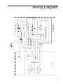
1
Gel Dryer Model FB-GD-45
User’s Manual
76875 • 4/10/06
Table of Contents
Safety Information ........................................................................................................................................................3
Purpose ................................................................................................................................................................3
Safety Information..................................................................................................................................................3
Unpacking ....................................................................................................................................................................4
Receiving and Unpacking......................................................................................................................................4
Parts Supplied ......................................................................................................................................................4
Set Up ..........................................................................................................................................................................5
Selecting a Location ..............................................................................................................................................5
Set up Procedure ..................................................................................................................................................5
Set up Diagrams....................................................................................................................................................6
Operation......................................................................................................................................................................7
Operation Procedure ............................................................................................................................................7
Control Panel Diagram ..........................................................................................................................................8
Approximate Drying Times ....................................................................................................................................9
Maintenance ..............................................................................................................................................................10
Cleaning ..............................................................................................................................................................10
Troubleshooting ..................................................................................................................................................11
Replacing the Cover Seal....................................................................................................................................12
Removing the Cover Seal....................................................................................................................................12
Installing the Cover Seal......................................................................................................................................12
Replacing the Vacuum Hose ..............................................................................................................................12
Removal of the Vacuum Hose ............................................................................................................................12
Installation of the Vacuum Hose ..........................................................................................................................13
Replacing Fuses ..................................................................................................................................................13
Fisher Service......................................................................................................................................................14
Instrument Service ..............................................................................................................................................14
Technical Service ................................................................................................................................................14
Specifications ............................................................................................................................................................15
Replacement Parts & Accessories ............................................................................................................................16
Wiring Diagram ..........................................................................................................................................................17
Warranty ....................................................................................................................................................................20
2
Safety Information
Alert Signals
Warning
A warning alerts you to actions or
conditions that can cause personal
injury.
Caution
A caution alerts you to actions or
conditions that can cause faulty
results or product damage.
Purpose
This manual applies to the FisherBiotech Gel Dryer. It is
written for those people who use and maintain the Gel
Dryer and its accessories.
Safety Information
Throughout this manual, visual cues are used to help you
identify important information.
Note
A note informs you that a special
condition exists or that a general rule
should be followed.
3
Unpacking
Caution
For proper operation and to ensure
compatibility with your Gel Dryer, use
only those accessories and options
provided by Fisher which are
designed specifically for the system.
Use only Fisher factory replacement
parts. If you need parts for your Gel
Dryer, contact Fisher’s Instrument
Service Division.
Plan the location of your Gel Dryer to
allow for easy operation.
Protect against physical damage. The
Gel Dryer should be protected from
dirt, spray and airborne debris.
Ensure that the unit is set up to confirm to local regulations and within the
guidelines for good laboratory practice.
Receiving and Unpacking the
Gel Dryer
Unpack the Gel Dryer and its accessories from the shipping container. Save this container for returning the unit in
the event that service is required.
Check the cartons and components for signs of damage.
Check the packing list to ensure all parts are present.
Damaged or missing items should be reported to the
shipping agent within 15 days.
If the Gel Dryer will not be set up immediately, store the
Gel Dryer and accessories in their original shipping containers until ready for installation. The storage area
should be clean and dry and should not subject the Gel
Dryer to extremes in temperature.
Parts Supplied
The following is a list of the parts and documents supplied
with the Gel Dryer.
1 power cord
3 vacuum hose connectors for 1/4”, 3/8”, and
1/2” I.D. hose
Caution
When not being used, the porous
support pad and the plastic support
mesh may be stored in the clear plastic bag supplied with the packaging.
However, to avoid damage to the Gel
Dryer’s surface, never allow the clear
plastic bag to contact the heated Gel
Dryer surface.
Handle the Gel Dryer with care. Do
not drop or subject the unit to
mechanical shocks.
4
1 warranty card
1 porous support pad
1 plastic support mesh
1 user’s manual
Set Up
Selecting a Location
The Gel Dryer should be set up on a level, stable laboratory bench or cabinet.
Locate the Gel Dryer so that there is at least 10 cm (4
inches) of clearance around the back, sides, and top of
the Gel Dryer.
Select a location for your Gel Dryer which has an appropriate source of electrical power. The power source must
correspond to the data plate mounted on the rear of the
unit.
Select a location away from solvent vapors and flammables where no explosion hazard exists.
Caution
Ensure that the timer knob is set to
“0” before plugging the Gel Dryer into
the power source.
Caution
Never allow the clear plastic bag to
come in contact with the heated Gel
Dryer surface.
Caution
The plastic support mesh must be in
place in order for the Gel Dryer to
perform properly.
Caution
Be careful not to over tighten the vacuum connector, as this may damage
the connector.
The Gel Dryer must be connected to a suitable vacuum
source for operation (see Specifications). Select a location which will allow convenient access to the vacuum
source.
Set Up Procedure
1.
Remove the unit from the shipping carton and
place it onto the laboratory bench.
2.
Plug the power cord into the Gel Dryer on the
right-hand side near the back of the unit.
3.
Plug the unit into the power source.
4.
Remove the plastic support mesh from the clear
plastic bag and place it, smooth side up, on the
platen of the Gel Dryer.
5.
Based on the inner diameter of the vacuum
hose you intend to use, select one of the two
vacuum hose connectors. Connectors are provided for 1/4”, 3/8”, and 1/2” inside diameter
hose.
6.
Thread the selected connector into the vacuum
outlet on the left side of the unit, in the clockwise direction. For this purpose, a 9/16” deepwell socket is recommended.
7.
Connect the Gel Dryer to the vacuum source
using thick-walled vacuum hose.
5
SET UP
Note
For the cover seal to seal automatically, the vacuum pump must be capable of achieving proper pressure and flow (see Specifications). Use of a high vacuum pump, such as the FisherBiotech
diaphragm vacuum pump or the Fisher Maxima D2A, will provide the fastest, most consistent drying
of your gels.
Caution
It is strongly recommended that both a liquid pretrap and a cold condensation trap be used to prevent
liquid or water vapor from damaging the vacuum pump. The condensation trap can be mechanically
refrigerated unit, or one can be constructed using a Dewar flask and a cold finger, or a vacuum flask
immersed in liquid nitrogen or packed dry ice. See Figure 1-2. If a diaphragm pump is used, a liquid
trap alone may be sufficient to protect it, See Figure 1-3.
6
Operation
Operation Procedure
1.
Roll the cover seal up or lay it back over the
control panel to expose the platen of the Gel
Dryer.
2.
Select a support for your gel and place it in the
platen of the Gel Dryer.
The plastic support mesh is sufficient for most
gels, and will allow for the shortest drying time.
Very soft gels may be imprinted by the support
mesh unless more than one sheet of filter paper
is placed under the gel. Also, some filter paper
residue may build up beneath the support mesh,
but regular removal of this residue will prevent
clogging of the system.
Caution
When using the porous support pad,
the plastic support mesh must still be
in place on the bottom of the Gel
Dryer platen in order for proper vacuum to be obtained.
The porous support pad may be more desirable
for very soft gels. However, drying time will be
significantly longer, especially for agarose gels.
3.
Place at least one sheet of moistened filter
paper (or chromatography paper), cut slightly
larger than your gel(s), on the selected gel support. When using the support mesh alone, two
or three thickness of paper are recommended.
Using thicker paper will require fewer layers.
Center the filter paper on the Gel Dryer if drying
only one gel
4.
Place the gel(s) on the filter paper and smooth
out any air bubbles.
5.
Place a porous membrane over the gel(s) and
remove any air bubbles from between the gel(s)
and the membrane.
6.
Place the cover seal over the gel(s) and smooth
out any air bubbles.
The plastic support mesh and the
porous support pad must each be
used with its smooth side up.
Note
DNA sequencing gels which are
already adhered to a sheet of filter
paper can be placed directly on the
support mesh.
Caution
Failure to cover the gel with a porous
membrane may cause the cover seal
to stick to the gel, which may result in
tearing of the gel.
7
OPERATION
7.
8
Turn the temperature knob to the desired setting. The Gel Dryer is
capable of heating from ambient temperature up to 80° C.
OPERATION
Note
If you wish to maintain a constant platen temperature below 20° C, place the
Gel Dryer in a cold environment and
turn the temperature knob to the white
area below the 20° C mark.
Note
When timer knob is turned, the power
indicator light illuminates to indicate
that power is on. The heater indicator
light illuminates when the heaters are
activated. The heaters will cycle on
and off once the set temperature is
reached in order to maintain the set
temperature.
The timer controls power to the
heaters only. When the set time
expires, only the heaters will turn off.
The vacuum must be switched off
manually.
8.
Use the timer control knob to turn on the power
and set the desired heating time. Turn the knob
clockwise to set time for up to 5 hours, or counterclockwise to 00 for continuous operation.
9.
Turn on the vacuum source. The cover seal will
automatically seal. The vacuum must be maintained until the gel is dry.
10. Turn off the heat and allow the gel to cool before
releasing the vacuum. This will help minimize
the dried gel.
11. Lift the cover seal before turning off the vacuum
source.
Approximate Drying Times
Polyacrylamide Gels will dry in about one hour at the temperature setting of 80° C when run with pumps specified
in the accessory section. Gels that are of higher concentration than a standard 6% Acrylamide Gel may require
longer drying times. The drying time for these applications
could be near 2 hours. Lower temperatures can be used
for thick or gradient Gels. The drying time is reduced by
having a good vacuum. The normal vacuum is in the
range of 10-40 mm Hg.
Caution
Releasing the vacuum before the gel is
completely dry may cause the gel to
crack.
9
Maintenance
Warning
NEVER immerse the Gel Dryer in
water. Unplug the Gel Dryer before
cleaning it.
Caution
Drying gels using only the plastic support mesh may cause a residue of filter
paper dust to accumulate on the platen. WIpe this residue out of the platen
with a damp cloth on a regular basis to
prevent clogging of the vacuum port.
Both the plastic support mesh and the
porous support pad are made of
polypropylene, and may be damaged
by exposure to certain organic solvents. They should be rinsed thoroughly with water after use and air dried. If
infectious agents are spilled on them,
they can be steam autoclaved to disinfect them.
10
Cleaning
The platen of the Gel Dryer is coated with Teflon. Use
only mild soap and water and a soft cloth for cleaning it.
DO NOT use abrasive cleaners or scouring pads.
MAINTENANCE
Troubleshooting
This table guides you in tracking down the cause of a problem based on a symptom description.
Symptom
Probable Cause
Recommended Action
Power Indicator light
does not illuminate
Timer not set
Turn timer knob past set point or 1
hour, then set point.
Power cord not plugged in
Make sure power cord is plugged into
wall outlet.
Power cord not plugged into
Gel Dryer
Make sure power cord is plugged into
Gel Dryer.
Faulty or blown fuse
Check fuse, replace if necessary.
Faulty power cord
Replace power cord.
Timer defective
Call Fisher Service.
Defective power indicator light
Call Fisher Service.
Temperature not set above
ambient
Set temperature above ambient.
Timer not set
Turn timer knob past set point or 1
hour, then to set point.
Electrical system failure
Call Fisher Service.
Platen heats to 95° C,
then shuts down
Temperature controller
failure
Call Fisher Service.
Platen heats, but heater
indicator does not light
Defective heater indicator
light
Call Fisher Service.
Cover seal does not seal
Cover seal misaligned
Reinstall cover seal.
Cover seal damaged
Replace cover seal.
Vacuum pump not functioning
Check pump.
Vacuum tubing leaks
Check tubing for leaks.
Vacuum tubing clogged
Check tubing for clogs
Failure to heat
11
MAINTENANCE
Replacing the Cover Seal
If the cover seal becomes misaligned or damaged, sufficient vacuum may not be attainable. The cover seal must
be reinstalled or replaced to correct the problem.
Removing the Cover Seal
A metal bar is used to hold the cover seal onto the platen.
To remove the cover seal, perform the following procedure:
1.
2.
Remove the five Phillips head screws securing
the metal bar.
Remove the bar and lift off cover seal.
Installing the Cover Seal
To install the replacement cover seal, reverse the steps in
the removal section taking care to align the holes in the
cover seal with the holes in the platen. Check to make
certain the cover seal is aligned over the platen edges to
insure proper vacuum seal.
Replacing the Vacuum Hose
Connector
The vacuum hose connector supplied with the Gel Dryer
may be replaced if necessary for repair or to install another vacuum hose connector for a different sized vacuum
hose.
Removal of the Vacuum Hose
To prevent damage to the vacuum hose connector, use a
9/16 inch deep well socket for removal, turning the connector in the counter-clockwise direction.
12
MAINTENANCE
Installation of the Vacuum Hose
Install the vacuum hose connector using a 9/16 inch deep
well socket, turning the connector in the clockwise direction. To protect the connector from damage, do not overtighten.
Replacing Fuses
To inspect and/or replace the fuses, perform the following
procedure:
1.
Remove the power cord from the wall outlet and
from the socket in the power input block. Locate
the fuse drawer in the power input block. See
Figure 3-2.
2.
Insert a small flat-bladed screwdriver or your fingernail under the right edge of the fuse drawer
and slide the fuse drawer out.
3.
Turn the fuse drawer over and you will see the
fuses inside. Pull the fuses out and inspect
them. If defective, replace with fuses of same
type and rating only.
4.
After replacing or reinserting the fuses, slide the
fuse drawer into the power input block until it
snaps into place.
5.
Reinsert the power cord into the power input
block.
13
MAINTENANCE
Fisher Service
Fisher Scientific actively supports the products it manufactures and distributes.
Instrument Service
Fisher Instrument Service representatives are skilled at
troubleshooting and repairing the Gel Dryer. Service is
available at any of the Instrument Service District Offices
located throughout the country. For service, or for information regarding service contracts or parts. Please call your
Fisher Scientific Service District Office.
Technical Service
Fisher maintains a technical support organization which is
available for help regarding use and maintenance of your
Gel Dryer. Our technical support group is staffed with
courteous and competent personnel trained in the use of
the Gel Dryer.
Fisher Technical Service-Hot-Line can be reached by
dialing: 1-800-388-8355
14
Specifications
Line Voltage
115 VAC
230 VAC
Line Frequency
50/60 Hz
Power Consumption
720 watts
Dimensions
HxWxD
3-7/8 x 25-13/16 x 17-3/4 inches
9.8 x 65.5 x 45.1 centimeters
Drying Surface
14-1/2 x 18-1/2 inches
36.8 x 47 centimeters
Weight
25.5 lbs (11.6 kg)
Temperature Control
ambient to 80° C
Timer on Heater
Zero to five hours; hold position
for continuous operation
Vacuum Pump
Requirements
Ultimate pressure; 10.7 mm Hg
Free air displacement; 29.5 L/min
Vacuum Hose Connectors
Accepts 1/4”, 3/8” or 1/2” vacuum hose
15
Replacement Parts & Accessories
Replacement Parts
Description
Fuses (115 V)
(230 V)
Fuse Drawer (115 V)
(230 V)
Power Input Block
Timer
Power/Heat Indicator Light (115 V)
(250 V)
Heaters
Thermal Fuse
Sensor
Temperature Controller (115 V)
Temperature Controller (230 V)
Power Cord (North America)
Vacuum Hose Connector (1/4” hose I.D.)
Vacuum Hose Connector (3/8” hose I.D.)
Vacuum Hose Connector (1/2” hose I.D.)
Plastic Support Mesh
Porous Support Pad
Cover Seal
Number
SPN 13775
SPN 83105
SPN 76867
SPN 83104
SPN 76866
SPN 76820
SPN 76865
SPN 93106
SPN 76821
SPN 76868
SPN 76825
SPN 83010
SPN 83188
15-188-37 A
FB-GD-20
FB-GD-21
Fb-GD-25
FB-GD-22
FB-GD-23
FB-GD-24
Reference
F1, F2
F1, F2
Fig. 3-2
Fig. 3-2
Pi
TMR
PLI
PLI
HTR I, HTR 2
TF
THM
TC
Accessory Items
Description
Vacuum Pump (Fisher Maxima D2A) (110 volt 50/60 Hz)
Diaphragm Vacuum Pump (110 volt 50/60 Hz)
(220 volt 50 Hz)
Liquid Trap
16
Fisher Catalog Number
01-057-2A
FB-DVP-353
FB-DVP-353A
FB-GDT-45
1
1
115V 330 WATTS
(40 OHMS)
HTR 2
115V 330 WATTS
(40 OHMS)
HTR 1
PLATEN
2
2
2
GRN/YEL
WHT
WHT
BLU
BLU
WHT
WHT
YEL
BLK
BLK
YEL
YEL
BLU
ORN
ORN
BLK
YEL
YEL
YEL
YEL
SPLICE #2
12
9
8
7
4
5
6
3
2
1
J2 / P2
BOTTOM
CHASSIS
RED
SPLICE #1
G
N.C.
MAIN
BL
K
240 V
T10
T9
T8
WHT
GRN/YEL
WHT
120 V
WHT/BLK
DPST
P1
L
T5
TC
INPUT
CONTROL PANEL \
MAIN CHASSIS
T4
T6
BLU
TEMPERATURE CONTROLLER
PL1
TMR
5 HR. N.O. W/HOLD
N
ER ENTRY MODU
RED
BLK
Wiring Diagram
17
Warranty
Laboratory instruments and equipment manufactured by Fisher Scientific Company L.L.C. – Laboratory
Equipment Division (hereinafter called “the Company”) are warranted only as stated below.
Subject to the exceptions and upon the conditions specified below, the Company agrees, at its election, to
correct by repair, by replacement, or by credit to the purchaser, any defect of materials or workmanship which
develops within one year (13 months for refrigerator and freezer products) from the date of purchase by the
original purchaser by the Company or by an authorized dealer of the Company provided that investigation or
factory inspection by the Company discloses that such defect developed under normal and proper use
The exceptions and conditions mentioned above are the following:
a. The Company makes no warranty concerning components or accessories not manufactured by it,
such as tubes, batteries, etc. However, in the event of the failure of any component or accessory not
manufactured by the Company, the Company will give reasonable assistance to the purchaser in
obtaining from the respective manufacturer whatever adjustment is reasonable in the light of the
manufacturer’s own warranty.
b.
The Company shall be released from all obligations under its warranty in the event repairs or
modifications are made by persons other than its own service personnel or authorized dealer
personnel unless such repairs by others are made with the written consent of the Company.
c.
THE COMPANY MAKES NO WARRANTY OF MERCHANTABILITY, FITNESS FOR ANY
PARTICULAR PURPOSE, OR ANY OTHER WARRANTY, EXPRESS OR IMPLIED, EITHER IN
FACT OF BY OPERATION OF LAW,…STATUTORY OR OTHERWISE.
d.
The above warranty and the above obligations to repair, replace, or credit are complete and
exclusive and the Company expressly disclaims liability for lost profits or for special, indirect,
incidental, consequential, or exemplary damages of any nature whether attributable to contract,
warranty, negligence, strict liability, or otherwise even if the Company has been advised of the
possibility of such damages.
e.
Representations and warranties made by any person, including dealers and representatives of the
Company, which are inconsistent or in conflict with the foregoing warranty shall not be binding upon
the Company unless reduced to writing and signed by an officer of the Company.
2555 Kerper Boulevard
Dubuque, Iowa 52001
Phone: 800-926-0505
Fax: 563-589-0516
www.fishersci.com