1
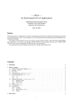
SUPPORTED ECU
COMMUNICATION PROTOCOLS
AND
AIM LOGGERS CONNECTION
User Manual
1
Ecu communication protocols and AIM loggers connection
User Manual
Release 1.45
INDICE
1 – ECU communication protocol”: general information ........................................... 3 2 – Supported ECUs: general information................................................................... 4 2.1 – ECU connection: general information ........................................................................................ 4 2.1.1 – Serial Communication Set-Up ................................................................................................. 4 2.1.2 – CAN Communication Set-Up ................................................................................................... 4 3 – AIM – PROPRIETARY CAN & RS232 PROTOCOL ................................................. 5 3.1 – CAN Asynchronous Messaging .................................................................................................. 5 3.1.1 – AIM “PROT_CAN” ................................................................................................................... 6 3.2 – RS232 – Serial protocol ................................................................................................................ 6 3.2.1 – AIM “PROT_UART” ................................................................................................................. 7 4 – BMW.......................................................................................................................... 8 4.1 – BMW Z4M COUPÉ ......................................................................................................................... 8 5 – CARMO ..................................................................................................................... 9 5.1 – CARMO AFI 2003 ........................................................................................................................... 9 5.1.1 – Connection with AIM Data logger ............................................................................................ 9 6 – DTA ......................................................................................................................... 10 6.1 – DTA P8.......................................................................................................................................... 10 6.1.1 – Serial Communication Set-Up ............................................................................................... 10 6.1.2 – Connection with AIM Data logger .......................................................................................... 10 7 – NIRA ........................................................................................................................ 11 7.1 – NIRA – I3+”................................................................................................................................... 11 8 – PERFORMANCE ELECTRONICS .......................................................................... 12 8.1 – PERFORMANCE ELECTRONIC ECU1 ....................................................................................... 12 8.1.1 – Connection with AIM Data logger .......................................................................................... 12 9 – SUBARU – SSM” .................................................................................................... 13 9.1 – Connection with AIM Data logger .............................................................................................. 13 10 – WALBRO .............................................................................................................. 14 10.1 – WALBEO BENELLI / BENELLI ’04 / BIMOTA / HPUH1” ......................................................... 14 10.1.1 – Connection with AIM Data logger ........................................................................................ 14 10.2 – WALBRO – A1BEN_00 .............................................................................................................. 14 11 – WOLF .................................................................................................................... 15 11.1 – WOLF 3D .................................................................................................................................... 15 11.1.1 – Connection with AIM Data logger ........................................................................................ 15 www.aim-sportline.com
2
Ecu communication protocols and AIM loggers connection
User Manual
Release 1.45
0
1 – ECU communication protocol”: general information
The “available channels list” of Race Studio 2 “Configuration” window comes from the
ECU communication protocol.
The communication protocol includes all the available channels of a generic Pectel /
DTA etc. ECU. The channels you may sample among the “available channels list” are
function of the ECU model, of the ECU configuration and of the wiring.
The number of channels that the data logger is able to sample depends on the
ECU type and configuration, on the wiring and on the sensors connected to the
ECU itself.
To know which channels are acquired by AIM logger, please check the logger
channel page in Race Studio 2 software, where all recorded channels are shown.
Note: for specific information on ECU pinout and wirings always refer to the ECU
user manual. Here follow some examples of ECU configuration and connection
with AIM loggers; these information come from tests made by AIM research and
development board or from dealers or customers that have verified them.
www.aim-sportline.com
3
Ecu communication protocols and AIM loggers connection
User Manual
Release 1.45
1
2 – Supported ECUs: general information
AIM loggers support both CAN and RS232 communication protocols.
11
2.1 – ECU connection: general information
AIM loggers can communicate with the ECU both with a CAN protocol and with an
RS232 protocol, using respectively a CAN cable or a Serial cable.
The connection is usually done as below explained:
23
2.1.1 – Serial Communication Set-Up
The usual connection is as follows: connect cable called RS232 RX with ECU TX and
cable called GND with ECU GND as shown below.
LOG GND
LOG RX
Cable labelled GND
ECU GND
ECU TX
Cable labelled RS232 RX
ECU
AIM LOGGER
Note: this setup is all right for almost all ECU communicating with RS232 protocol; there
can anyway be ECUs that need LOG TX cable to be connected to ECU RX too. For
further information, see the following paragraphs, related to the single ECUs or single
ECU documents published on AIM website www.aim-sportline.com.
24
2.1.2 – CAN Communication Set-Up
The connection is as follow: connect cable labelled CAN+ with ECU CAN+, cable
labelled CAN- with ECU CAN- and cable called GND with ECU GND as in the figure
below.
LOG GND
LOG CAN+
LOG CAN-
Cable labelled GND
Cable labelled CAN +
Cable labelled CAN -
AIM LOGGER
ECU GND
ECU CAN+
ECU CANECU
Note: once the ECU is connected to AIM Logger, it needs to be set in the logger
configuration in Race Studio 2 software.
www.aim-sportline.com
4
Ecu communication protocols and AIM loggers connection
User Manual
Release 1.45
2
12
3 – AIM – PROPRIETARY CAN & RS232 PROTOCOL
3.1 – CAN Asynchronous Messaging
AIM technique is referred to as Asynchronous messaging, basically the whole stream of
parameters (all 35 Bytes) is split up into 8 bytes-length packets, that are sequentially
inserted into CAN messages and in a given order. The data packets do not contain a
specific identifier, they are just in a predefined order. At the receiving node the device
looks for the Header information (this is a constant contained in the data stream), when
this is seen the device knows that next message is the start of the data stream and all
subsequent CAN messages will contain the given parameters in the predefined order.
This way the CAN system is simply a carrier for seemingly highly variable data under a
single base addresses and the software handlers at either end know how to breakdown
and reassemble these separate packets of data into a continuous and complete data
stream.
The CAN bus has a bit rate of 1Mbit/s and the CAN Buffer Identifier is 11bit.(CAN 2.0a)
CheckSum is the sum of all bytes of the structure up to and including marker byte 3.
Byte
Signal
Units
0:1
2:3
4:5
6:7
8:9
10:11
12:13
14:15
16:17
18:19
20:21
22:23
24:25
26:27
28:29
30
31
32
33
34
RPM
Wheel Speed
Oil Pressure
Oil Temperature
Water Temperature
Fuel Pressure
Battery Voltage
Throttle Angle
Manifold Pressure
Air Charge Temperature
Exhaust Gas Temperature
Lambda
Fuel Temperature
Gear
Errors
Number of Data Bytes
Marker Byte 1
Marker Byte 2
Marker Byte 3
CheckSum
RPM
Km/h
Bar
Deg C
Deg C
Bar
Volts
%
mBar
Deg C
Deg C
Lambda
Deg C
0=neutral,1=first,2=second,etc
ECU-specific error flags
30
FC
FB
FA
www.aim-sportline.com
Scaling
1RPM
0.1km/h
0.1Bar
0.1Deg C
0.1Deg C
0.1Bar
0.01Volts
0.1%
1mBar
0.1Deg C
1Deg C
0.001 La
0.1Deg C
5
Ecu communication protocols and AIM loggers connection
User Manual
Release 1.45
31
3.1.1 – AIM “PROT_CAN”
ECU_1
ECU_2
ECU_3
ECU_4
ECU_5
ECU_6
ECU_7
ECU_8
ECU_9
ECU_10
ECU_11
ECU_12
ECU_13
ECU_14
ECU_15
13
AIM_RPM
AIM_WHEELSPEED
AIM_OILPRESS
AIM_OILTEMP
AIM_WATERTEMP
AIM_FUELPRESS
AIM_BATTVOLT
AIM_TPS
AIM_MAP
AIM_AIRTEMP
AIM_EXHAUST_TEMP
AIM_LAMBDA
AIM_FUELTEMP
AIM_GEAR
AIM_ERRORS
RPM
vehicle speed
oil pressure
oil temperature
water temperature
fuel pressure
battery voltage
throttle position
manifold pressure
intake air temperature
exhaust temperature
lambda value
fuel temperature
engaged gear
error signal
3.2 – RS232 – Serial protocol
The data stream is standard RS232 at 19200,n,8,1. It consists of a number of short
packets. Packets are sent on 10 ms ticks. Note that this does not mean that there is a
packet sent every 10 ms tick – there is a pattern which repeats once a second to
achieve the channel frequencies listed below, and there are some unused ticks where
nothing is transmitted. Each packet consists of 5 bytes. The first byte is the channel
number, the second is always A3H, the third and fourth are the channel value, high byte
first. The fifth is the sum of the preceding four bytes.
Signal
Channel
RPM
Wheel speed
Oil pressure
Oil temp
Water temp
Fuel pressure
Battery voltage
Throttle angle
Manifold press
Air charge temp
Exhaust temp
Lambda Sensor
Fuel temp
Gear
Errors
1
5
9
13
17
21
33
45
69
97
101
105
109
113
125
Freq
[Hz]
10
10
5
2
2
5
5
10
10
2
2
10
2
5
2
Transform
y=x
y=x/10
y=x/1000
y=x/10-100
y=x/10-100
y=x/1000
y=x/100
y=x/10
y=x
y=x/10-100
y=x/10-100
y=x/1000
y=x/10-100
y=x
-
Units
RPM
Km/h
Bar
Deg C
Deg C
Bar
Volts
Deg
MBar
Deg C
Deg C
Lambda
Deg C
0=rev, 1=neutral, 2=first, 3=second…
ECU-specific error flags
www.aim-sportline.com
6
Ecu communication protocols and AIM loggers connection
User Manual
Release 1.45
32
3.2.1 – AIM “PROT_UART”
ECU_1
ECU_2
ECU_3
ECU_4
ECU_5
ECU_6
ECU_7
ECU_8
ECU_9
ECU_10
ECU_11
ECU_12
ECU_13
ECU_14
ECU_15
AIM_RPM
AIM_WHEELSPEED
AIM_OILPRESS
AIM_OILTEMP
AIM_WATERTEMP
AIM_FUELPRESS
AIM_BATTVOLT
AIM_THROTANG
AIM_MANIFPRESS
AIM_AIRCHARGETEMP
AIM_EXHTEMP
AIM_LAMBDA
AIM_FUELTEMP
AIM_GEAR
AIM_ERRORFLAG
RPM
Vehicle speed
Oil pressure
Oil temperature
Water temperature
Fuel pressure
Battery voltage
Throttle position
Manifold pressure
Intake air temperature
Exhaust temperature
Lambda value
Fuel temperature
Engaged gear
Error signal
www.aim-sportline.com
7
Ecu communication protocols and AIM loggers connection
User Manual
Release 1.45
3
22
4 – BMW
4.1 – BMW Z4M COUPÉ
ECU_1
ECU_2
ECU_3
ECU_4
ECU_5
ECU_6
ECU_7
ECU_8
ECU_9
ECU_10
ECU_11
ECU_12
ECU_13
ECU_14
ECU_15
ECU_16
ECU_17
ECU_18
ECU_19
ECU_20
ECU_21
ECU_22
ECU_23
ECU_24
ECU_25
ECU_26
ECU_27
ECU_28
ECU_29
ECU_30
ECU_31
ECU_32
ECU_33
ECU_34
ECU_35
ECU_36
ECU_37
ECU_38
ECU_39
BMW_RPM
BMW_IGN_ANG
BMW_TPS
BMW_GEAR_LEVER
BMW_VANOS
BMW_TPS_KORR_DSC
BMW_EGAS_POS
BMW_ECU_STATE
BMW_AZ_KORR_DSC
BMW_AIR_PRESS_DYN
BMW_OIL_TEMP
BMW_WATER_TEMP
BMW_FUEL_TEMP
BMW_AIR_TEMP
BMW_DIFF_TEMP
BMW_GEAR_TEMP
BMW_ECU_TEMP
BMW_CURRENT
BMW_PSLIM_STATE
BMW_GEAR
BMW_FUEL_LEVEL
BMW_SW_STATE
BMW_FUEL_PRESS
BMW_WATER_PRESS
BMW_OIL_PRESS
BMW_VBATT
BMW_BRK_PFL
BMW_BRK_PFR
BMW_BRK_PRL
BMW_BRK_PRR
BMW_P400_N
BMW_P400_C
BMW_P_400T
BMW_SPEED_FL
BMW_SPEED_FR
BMW_SPEED_RL
BMW_SPEED_RR
BMW_LMBD1
BMW_LMBD2
www.aim-sportline.com
RPM
Ignition advance angle
Throttle position
Gear lever position
Variable valve timing
Oil temperature
Water temperature
Fuel temperature
Intake air temperature
Differential temperature
Gear box oil temperature
Ecu temperature
Engaged gear
Fuel level
Fuel pressure
Water pressure
Oil pressure
Battery voltage
Brake pressure front left w.
Brake pressure front right w.
Brake pressure rear left w.
Brake pressure rear right w.
*** No info available yet***
*** No info available yet***
*** No info available yet***
Vehicle speed – front left wheel
Vehicle speed – front right wheel
Vehicle speed – rear left wheel
Vehicle speed – rear right wheel
Lambda value#1
Lambda value#2
8
Ecu communication protocols and AIM loggers connection
User Manual
Release 1.45
4
14
5 – CARMO
5.1 – CARMO AFI 2003
AIM loggers can be connected to both Carmo ignition or injection unit (AFI 2003); they
can acquire data from Carmo units installed on Honda CBR600, Kawasaki ZX6R,
Yamaha YZ6F and Suzuki GSXR600.
The configuration procedure is the same for every bike; when the channels to acquire or
to display have been selected, the logger will automatically select the right set of
sensors, using the information given by AFI unit.
NOTE: each manufacturer has its own set of sensors; if the set of sensors is not the one
used by the manufacturer for that type of bike, acquired data could be wrong.
Injection unit
When the logger is connected to the injection unit all channels listed in the configuration
dialog window are available.
Ignition unit
When the logger is connected to the ignition unit only RPM and Throttle Position
channels are available. In this case we recommend to disable the other ECU channels
in order to save memory.
25
5.1.1 – Connection with AIM Data logger
Connect cable labelled RS 232 RX with ECU TX pin, cable called RS 232 TX with ECU
RX pin and cable called GND with ECU Power GND pin as shown below.
Refer to the ECU user manual to know the ECU pinout.
LOG GND
LOG RX
LOG TX
Cable labelled GND
Cable labelled RS232 RX
Cable labelled RS232 TX
ECU GND
ECU TX
ECU RX
CARMO AFI 2003 ECU
Note: this ECU needs connection of LOG TX cable to ECU RX pin too.
ECU_1
ECU_2
ECU_3
ECU_4
ECU_5
ECU_6
CARMO_RPM
CARMO_THROTTLE
CARMO_AIRTEMP
CARMO_WATERTEMP
CARMO_MANIFPRES
CARMO_BATTERY
RPM
THROTTLE POSITION
INTAKE AIR TEMPERATURE
WATER TEMPERATURE
MANIFOLD PRESSURE
BATTERY VOLTAGE
www.aim-sportline.com
9
Ecu communication protocols and AIM loggers connection
User Manual
Release 1.45
5
15
26
6 – DTA
6.1 – DTA P8
6.1.1 – Serial Communication Set-Up
The ECU is equipped with a serial communication interface (RS232) used to
communicate parameters to an external data logger, or to configure the ECU itself.
27
6.1.2 – Connection with AIM Data logger
To connect AIM logger to the ECU connect AIM cable labelled “RS232RX” with ECU
TX, AIM cable labelled as “GND” with ECU GND as shown below.
Refer to the ECU user manual to know ECU pinout.
LOG GND
LOG RX
Cable labelled GND
Cable labelled RS232 RX
AIM LOGGER
ECU_1
ECU_2
ECU_3
ECU_4
ECU_5
ECU_6
ECU_7
ECU_8
ECU GND
ECU TX
DTA P8 ECU
DTA_RPM
DTA_WHEELSPD
DTA_WATERTEMP
DTA_AIRTEMP
DTA_MANIFPRESS
DTA_THROTANG
DTA_LAMBDA
DTA_BATTV
www.aim-sportline.com
RPM
Vehicle speed
Water temperature
Intake air temperature
Manifold pressure
Throttle position
Lambda value
Battery voltage
10
Ecu communication protocols and AIM loggers connection
User Manual
Release 1.45
6
16
7 – NIRA
7.1 – NIRA – I3+”
The communication is done over an RS232 link to NIRA i3+. Her below is ECU pinout.
ECU_1
ECU_2
ECU_3
ECU_4
ECU_5
ECU_6
ECU_7
ECU_8
ECU_9
ECU_10
ECU_11
ECU_12
NIRA_RPM
NIRA_WATER_TEMP
NIRA_BATTERY_VOLT
NIRA_TPS
NIRA_MAP
NIRA_AIRTEMP
NIRA_EXAUST_GAS_TEMP
NIRA_LAMBDA
NIRA_AUX1
NIRA_AUX2
NIRA_AUX3
NIRA_AUX4
www.aim-sportline.com
RPM
Water temperature
Battery voltage
Throttle position
Manifold pressure
Intake air temperature
Exhaust temperature
Lambda value
Auxiliary channel#1
Auxiliary channel#2
Auxiliary channel#3
Auxiliary channel#4
11
Ecu communication protocols and AIM loggers connection
User Manual
Release 1.45
7
17
8 – PERFORMANCE ELECTRONICS
8.1 – PERFORMANCE ELECTRONIC ECU1
The ECU is equipped with a serial communication interface (RS232) used to
communicate parameters to an external data logger, or to configure the ECU itself.
28
8.1.1 – Connection with AIM Data logger
AIM loggers can be connected to Performance Electronics ECU via DB9 serial port
according to the following wiring scheme:
•
•
Connect the AIM cable labeled “RS 232 RX” with DB9 male Pin 2
Connect the AIM cable labeled “RS 232 TX” with DB9 male Pin 3
Ecu Channel Table
ECU_1
ECU_2
ECU_3
ECU_4
ECU_5
PERF_RPM
PERF_TPS
PERF_MAP
PERF_IAT
PERF_ECT
www.aim-sportline.com
RPM
Throttle position
Manifold pressure
Intake air temperature
Water temperature
12
Ecu communication protocols and AIM loggers connection
User Manual
Release 1.45
8
9 – SUBARU – SSM”
This chapter applies to all Subaru vehicles supporting the SSM (Subaru Select Monitor)
with OBD2 connector (from 1999 to 2007). The number of supported channels may vary
and depends on car model and year of production.
18
9.1 – Connection with AIM Data logger
In order to connect the data logger to the SUBARU SSM ECU, AIM GPI01 interface is
to be connected to both AIM logger and the ECU as shown below.
ECU Channel Table
ECU_1
ECU_2
ECU_3
ECU_4
ECU_5
ECU_6
ECU_7
ECU_8
ECU_9
ECU_10
ECU_11
ECU_12
ECU_13
ECU_14
ECU_15
RPM
SPEED
TPS
ECT
TURBO_PRESS
IN_VVT_R
IN_VVT_L
IGN_ADV
KNOCK_CORR
FUEL_LEV
NEUTRAL
CLUTCH
BRAKE
ENGINE_LOAD
AIR_FLOW
www.aim-sportline.com
RPM
Vehicle speed
Throttle position
Engine coolant temperature
Turbo pressure
Variable valve timing – right bank
Variable valve timing – left bank
Ignition advance
Knock angle correction
Fuel level
Neutral signal
Clutch switch on/off
Brake switch on/off
Engine load
Intake air flow
13
Ecu communication protocols and AIM loggers connection
User Manual
Release 1.45
9
19
10 – WALBRO
10.1 – WALBEO BENELLI / BENELLI ’04 / BIMOTA / HPUH1”
Each ECU is equipped with a serial communication interface (RS 232) used to
communicate parameters to an external data logger, or to configure the ECU itself.
29
10.1.1 – Connection with AIM Data logger
AIM loggers can be connected to WALBRO ECUs via DB9 serial port according to the
following wiring scheme:
•
•
20
Connect the AIM cable labeled “RS 232 TX” with DB9 male Pin 2
Connect the AIM cable labeled “RS 232 RX” with DB9 male Pin 3
10.2 – WALBRO – A1BEN_00
ECU_1
ECU_2
ECU_3
ECU_4
ECU_5
ECU_6
ECU_7
ECU_8
ECU_9
ECU_10
ECU_11
ECU_12
ECU_13
RPM
MAP
TPS
TAIR
TENGINE
VBATT
LAMBDA
IDLEPOSITION
DERIVTPS
SIDE_STAND
NEUTRAL
MAPPA_ATTIVA
TIPO_OVER
RPM
Manifold pressure
Throttle position
Intake air temperature
Engine temperature
Battery voltage
Lambda value
Idle position
Throttle position derivative
Side stand on/off
Neutral gear signal
Selected engine map
Tip over sensor on/off
www.aim-sportline.com
14
Ecu communication protocols and AIM loggers connection
User Manual
Release 1.45
10
21
11 – WOLF
11.1 – WOLF 3D
The ECU is equipped with a serial communication interface (RS 232) used to
communicate parameters to an external data logger, or to configure the ECU itself.
30
11.1.1 – Connection with AIM Data logger
AIM loggers can be connected to WOLF ECU via DB9 serial port according to the
following wiring scheme:
ECU_1
ECU_2
ECU_3
ECU_4
ECU_5
ECU_6
ECU_7
ECU_8
ECU_9
ECU_10
ECU_11
ECU_12
ECU_13
ECU_14
ECU_15
ECU_16
WOLF_RPM
WOLF_LOAD
WOLF_TURBOP
WOLF_MAP
WOLF_INJT
WOLF_INJ_DC
WOLF_IGNANG
WOLF_TPS
WOLF_AIRT
WOLF_ENGT
WOLF_OXYGEN
WOLF_BATT
WOLF_IDLE_VALVE
WOLF_NOISE
WOLF_AFR
WOLF_ERR
www.aim-sportline.com
RPM
Engine load
Boost pressure
Manifold pressure
Injection time
Injector duty cycle (0-100%)
Ignition advance angle
Throttle position
Intake air temperature
Engine temperature
Lambda raw voltage
Battery voltage
Idle valve position
False signals counter
Air/fuel ratio
Error signal
15