1
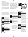
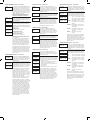
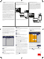
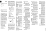
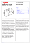
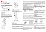
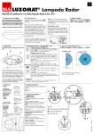
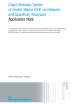
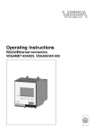
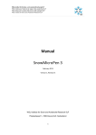
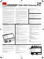
EN LUXOMAT ® DALI/KNX Gateway IP-N Installation and operating instructions 1. General use B.E.G. DALI Gateways bring together the crossfunctional KNX installation bus and the lighting control specific DALI-Bus (IEC 60929). Lights with cost-effective, digital DALI ECGs can therefore be integrated into an overall KNX architecture and operated via the multitude of existing KNX devices. Numerous communication objects are available for the visualisation of status and error information on an ECG as well as group and gateway level. (Current application: 11 communication objects per ECG and 8 communication objects per group + numerous individual objects). The B.E.G. DALI/KNX Gateway IP-N is a device used to control ECGs with a DALI interface via KNX. The device transforms switch and dim commands from the connected KNX system into DALI telegrams and status information from the DALI bus into KNX telegrams. In addition to all standard operating devices, the DALI/KNX Gateway IP-N also allows the control of individual battery emergency lights (EN 62386-202). For individual battery emergency lights, a distinction is made between devices with switchable ECGs (usually emergency lights with one ECG) and devices with non-switchable ECGs (converters), which are usually used in connection with another “normal” ECG (2 ECGs per light). The DALI/KNX Gateway IP-N allows for the mixed control of different ECG types within a DALI segment. Emergency lighting systems with a central battery are also supported. The DALI/KNX Gateway IP-N is a Category 1 device (in accordance with EN 62386-103). This means the device must only be used in DALI segments with connected ECGs and not with other DALI control devices within the segment (No multi-master function). Power supply for the up to 64 connected ECGs comes directly from the DALI/KNX Gateway IP-N. An additional DALI power supply is not required and not permitted. The device comes in a 4TE wide DIN Rail casing so it can be directly integrated into the mains distribution box. Connection to the bus is via a bus connector. Network and DALI lines are connected via screw connectors on the device. ECGs can be switched, dimmed and set to a defined value in 16 groups per gateway. In addition to group control, the DALI/KNX Gateway IP-N offers the possibility to individually control up to 64 ECGs. A scene module for the extensive programming of up to 16 scenes from groups and individual ECGs as well as an effect module for the control of processes and light effects are also available on the device. The DALI/KNX Gateway IP-N enables different forms of DALI commissioning (allocation of DALI ECGs to individual groups and changes in configuration): 1. Commissioning on the device 2. Commissioning via integrated web server Please remember that once ECGs have been assigned to a group, they can no longer be controlled individually. An ECG can only be allocated to one DALI group. The DALI/KNX Gateway IP-N does not support multi-group allocations. If multi-group allocation is required, it must be performed via KNX communication objects. The ETS (Engineering Tool Software) with the data base entry of the current application program is also required for the final commissioning of the KNX communication. 5. Installation advice 6. Technical data • Risk of death by electric shock Power supplies • Mains connector for 100 to 240 V, 50 to 60 Hz AC or DC • Maximum power consumption 7 W • In addition via KNX bus, SELV 24 V • The device is intended for interior installation in dry rooms. • T he device must only be installed and commissioned by an accredited electrical engineer. • P lease follow country-specific safety and accident prevention rules as well as all current KNX guidelines. • P lease follow country-specific rules and regulations for the planning and construction of installations, especially with regard to emergency lighting systems. • F or the installation the device must be switched to zero potential. • D o not open the device! Faulty devices must be returned to the manufacturer. For more details regarding the commissioning of a DALI segment, please see the current application program description. Connectors • Mains connector L N PE: Screw connector 3x 1- 2.5 mm² single or threaded core • DALI-Bus D+, D-: Screw connector 2x 1-2.5 mm² single or threaded core • Bus connector: KNX bus connector • Ethernet Eth1: RJ-45 plug connector for standard patch cables Control elements • Programming Button to toggle between normal and addressing mode • 3 buttons (Move, Prg/Set, ESC) on display front to commission the device and set parameters Display elements • LED red:Indicates normal/addressing mode • LNK-LED yellow: Signals device Ethernet readiness • ERR-LED red: Signals fault status • LC-Display, 2x12 characters: for the commissioning and configuration menu Inputs • Passive input for connecting pushbuttons with auxiliary voltage • 9 - 32 VDC or 8 - 26 VAC, cable length max. 15 m Output DALI-Bus • Connection of up to 64 ECGs in accordance with IEC 60926 • DALI-Voltage 16-20 VDC, short circuit proof max. 250 mA • Category-1 device (in accordance with EN 62386-103). No other control devices (DALI-Master) must be used. • Additional DALI power supply is not required or permitted. Ethernet • IP-connection via Ethernet, speed 100 Mbit / second • IP address allocation via DHCP service or fixed IP address 7. L ocation and function of indication and control elements The device connectors as well as the programming button and programming LED that are required for commissioning are only accessible in the distribution box when the cover is removed. The 3 buttons (MOVE, Prg/Set, ESC) that are required to commission and configure the DALI and the 2-line display and control LEDs (ERR und LNK) are accessible when the cover is closed. The following connectors can be found on the underside of the REG casing (left to right): A1: RJ-45 plug for Ethernet connection A2: KNX bus connector A3: Power supply connector The following elements can be found on the upper side of the REG casing (left to right): A4: DALI output connector A5: Programming LED for normal/addressing mode A6: Programming button normal/addressing mode The following elements can be found on the device front: A7: MOVE button A8: Prg/Set button A9: ESC button A10:Error-LED A11:Ethernet-LNK-LED A12: Display 2x12 characters for DALI configuration You must follow the terminal pin assignment as labelled on the casing! 2 . Device types and accessories At present, the following device types are available from the DaliControl product group: DALI/KNX Gateway IP-N Part number 90134 3. Scope of delivery The following individual components are included in the delivery of the DALI/KNX Gateway IP-N device: • Complete device with connected bus connector •1x heat shrinkable tubing 1.2 x 2 cm for additional insulation of the bus cable • Operating and mounting instructions • Delivered in break-proof individual packaging 4. Application programs The following application programs are currently available for the DALI/KNX Gateway IP-N device: DALI/KNX Gateway IP-N For application program functions, please see the application program description. Connections • Bus line: KNX bus terminal • Mains supply: Screw terminal for individual wires up to 2.5 mm² or 2 x 1.5 mm² • DALI bus: Screw terminal for individual wires up to 2.5 mm² or 2 x 1.5 mm² • Input for connecting pushbuttons, each contact: Screw terminal for individual wires up to 2.5 mm² or 2 x 1.5 mm² • Ethernet: RJ45 connector for standard patch cable Mechanical data • DALI/KNX Gateway IP-N casing: Plastic ABS – V0 • Dimensions REG casing 4TE: Width: 72mm, Height: 55 mm, Length: 86 mm • Weight 200 g • Mounting: 35 mm DIN rail Electrical safety • Pollution class (in accordance with EN60664-1): 2 • Protection type (in accordance with EN 60529): IP20 • Protection class (according to IEC 1140) I • Overvoltage category: III • KNX Bus: eparated extra-low voltage SELV DC 24 V • DALI Bus: Functional extra-low voltage FELV DC 18 V (base isolation) EMC requirements Complies with EN 50090-2-2 Environmental conditions • Weather resistence: EN 50090-2-2, • Environmental conditions during operation: -5°C to +45°C • Storage temperature: -25°C to +70°C • Rel. humidity (non condensing): 5 % to 93 % Certification KNX certified CE-Signage According to EMC-Guidelines (Residential and commercial buildings), Low Voltage guidelines A4 A5 A6 A10 A11 A9 A7 A8 A12 A1 A2 A3 8. Installation and wiring The DALI/KNX Gateway IP-N is a REG device and is therefore suitable for direct mounting in consumer units on 35 mm DIN rails. Once the device has been mounted, the connecting cable for the DALI bus should be led to the top left terminal. According to familiy of standards EN 62386, DALI control lines can be led together with the power line in a 5-wire cable (single basic insulation is sufficient). However, clear marking must be ensured. For the entire DALI installation in a segment, a maximum line length of 300 m must not be exceeded (recommended cross section 1.5 mm²). Once the DALI line is connected, the two external pushbuttons can be connected according to the connection scheme, if required. The button inputs are passive, which means that an auxiliary voltage of 8 - 26 V AC or 9 - 32 V DC is required. The mains voltage is connected to the bottom right-hand terminal according to the instructions marked on the casing. To connect the KNX line, a standard bus terminal is inserted in the corresponding terminal slot on the device. Ensure double basic insulation between the KNX installation and the mains voltage. To do this, provide additional insulation on the wires of the KNX line to the bus terminal using the shrink sleeve provided. Once all the connections have been made and the supply voltage has been switched on, the firmware version is indicated in the display. The flashing green PWR LED indicates that the device is ready to operate. If the device is started up without KNX, the red ERR LED lights up. If the ERR LED remains lit even when the KNX voltage is connected, this indicates a short circuit within the DALI segment (see also „SYSTEM TEST“ submenu below). In this case, please check the wiring of the DALI segment. DALI EB DALI EB DALI EB DALI EB DALI EB DALI EB DALI EB DALI EB For the DALI/KNX Gateway IP-N, the DALI segment can also be started up easily via the integrated web server. The device has an RJ45 socket on the bottom right-hand side above the bus terminal. A standard patch cable can be used to connect the device with a switch or router for the IP network (Ethernet). The connection is usually only required during startup and can be temporary. Once startup is complete, the Ethernet connection is no longer required for normal operation. When connecting the network connection, run the cable carefully to ensure sufficient distance between the IP cable and the mains supply. 9. Operation and menu structure It is possible to start up the connected DALI segment, and set and modify the DALI parameters, using just the three buttons (Move, Set/Prg, ESC) and the 2 x 12 character display on the front of the device. The operating concept is menu-driven. Depending on the menu position, up to two sublevels can be selected. The relevant menu position is indicated in the display. To navigate within the menu, press the relevant buttons briefly. The Move button is used to select the next menu item within a level. Pressing the Prg/Set button briefly accesses the level below. Pressing the ESC button exits the selected level and returns to the level above. Main menu – Level 1 The main menu level (level 1) has the following structure: To activate a process or change a parameter setting in a lower level, change to programming mode at the selected point by holding the Prg/Set button for > 2 sec. When the relevant function is in programming mode, a g symbol appears in the display. If programming mode is active, a parameter or setting can be modified by pressing the Move button. Pressing the Prg/Set button again briefly exits the process. The set parameter is saved or the relevant process is activated. DALI/KNX Gateway submenu – Level 2 From the main Dali Control menu, the DALI CONTROL LANGUAGE submenu is accessed by briefly V.2.0 pressing the Prg/Set button. LANGUAGE ENGLISH DALI CONTROL V.2.0 The firmware version is indicated. The display language can be set in the lowerlevel menu. IP ADDRESS In the lower-level menu, the IP address set in the ETS or assigned by the DHCP server is indicated. REINSTALLATION POSTINSTALLATION In the lower-level menu, on a reinstallation of a DALI segment, the connected DALI devices are reset and an automatic search for electronic ballasts is started (all previously available electronic ballasts are deleted). IP ADDRESS submenu – Level 2 In the lower-level menu, on a post-installation of DALI electronic ballasts, the automatic search is started and the configuration is compared, if necessary (only new electronic ballasts are found and indicated, old electronic ballasts remain). IP:192.168. 004.101 GROUP ASSIGNMENT In the lower-level menus, the electronic ballasts that are found are assigned to the desired DALI groups. GROUP PARAMETERS In the lower-level menus, the parameters of the individual groups can be set and modified. SCENE ASSIGNMENT In the lower-level menus, the desired and relevant groups can be assigned to the DALI scenes. GROUP TEST In the lower-level menu, the entire system (broadcast) and the individual groups can be switched on and off for test purposes. SCENE TEST In the lower-level menu, the individual programmed scenes can be called for test purposes. SYSTEM TEST FUNCTION INPUT B1 FUNCTION INPUT B2 The submenu indicates the display language that is currently set. Hold down the Prg/Set button to change to programming mode. Then use the Move button to select the language: GERMAN, ENGLISH, FRENCH, SPANISH, SWEDISH. Press the Prg/Set button briefly to confirm the selection. The set parameter is saved and the display now operates in the relevant language. In the lower-level menu, existing system errors can be called individually. In the lower-level menus, the function of floating button input B1 can be set. – as above – IP ADDRESS POST-INSTALLATION submenu – Level 2 POSTINSTALLATION Hold down the Prg/Set button to change to SEARCH programming mode. Pressing the Prg/Set via PROG MODE DEL. ELEC BALLASTS: 3 NEW BALLASTS: 1 DEL./NEW BALLASTS: 3/1 From the main IP ADDRESS menu, the submenu is accessed by briefly pressing the Prg/Set button. In the submenu, the IP address set in the ETS or assigned by the DHCP server in the IP network is indicated. The setting cannot be modified on the device. It must be set via the ETS or via DHCP. From the main REINSTALLATION menu, the SEARCH via PROG MODE submenu is accessed by briefly pressing the Prg/Set button. Hold down the Prg/Set button to change to SEARCH programming mode. Pressing the Prg/Set via PROG MODE button again briefly starts the initialisation and search process. First, all electronic ELECTRONIC ballasts connected to the DALI segment are BALLASTS: 47 reset automatically and any previously set parameters and group assignments are deleted. Then a search is performed for the connected electronic ballasts using their randomly generated long address and they are detected automatically in ascending order. Depending on the number of connected electronic ballasts, the search may take a few minutes. When the search is complete, the number of electronic ballasts found is indicated in the display. Pressing the ESC button returns to the level above (or the system returns there automatically after approx. 30 sec.). button again briefly starts the verification and search process. A search is performed for the connected electronic ballasts using their long address and they are automatically compared with the previous configuration. If electronic ballasts have been removed from the DALI segment, the relevant entries in the device are deleted automatically. During the verification process, the number of deleted devices is indicated. Then a search is performed for new installed devices in the DALI segment. Newly added electronic ballasts are reset automatically and any previously set parameters and group assignments are deleted. Depending on the number of connected electronic ballasts, the search may take a few minutes. During the search, the number of new devices found is indicated in the display. Once the entire process is complete (verification and search), the number of deleted devices and the number of new devices found are indicated in the display (deleted devices/new devices, from left to right, see image on the left). Pressing the ESC button returns to the level above (or the system returns there automatically after approx. 30 sec.). REINSTALLATION submenu – Level 2 REINSTALLATION From the main POST-INSTALLATION menu, the SEARCH via PROG MODE submenu is accessed by briefly pressing the Prg/Set button. GROUP ASSIGNMENT submenu – Level 2 and 3 GROUP ASSIGNMENT EB No.: 12 GROUP: -EB No.: 12 GROUP: 1 From the main GROUP ASSIGNMENT menu, the submenu is accessed by briefly pressing the Prg/Set button. In this menu, the individual electronic ballasts found by the search can be assigned to the 16 DALI groups, and existing assignments can be changed. In the submenu, scroll through the various electronic ballasts found by briefly pressing the Move button. The first display line indicates the number of the selected electronic ballast (EB). When an electronic ballast is selected, the connected lamp flashes. This enables the programmer to determine which lamp is assigned to the relevant number. Hold down the Prg/Set button to change to programming mode. Briefly press the Move button to set the group to which the electronic ballast should be assigned. Once the desired group is selected, confirm and save the setting by briefly pressing the Prg/Set button. On a reinstallation, perform this process once for all the electronic ballasts found. Pressing the ESC button returns to the level above (or the system returns there automatically after approx. 30 sec.). GROUP PARAMETERS submenu – Level 2 and 3 GROUP PARAMETERS GROUP: 01 PARAMETERS From the main GROUP PARAMETERS menu, the submenu is accessed by briefly pressing the Prg/Set button. In this menu, the individual parameters can be set for each group. In general, the group parameters should be set in the ETS during KNX startup. Direct settings on the device are only used to quickly change individual parameters. Please note that each ETS download overwrites any settings made on the device. In the submenu, scroll through the individual groups by briefly pressing the Move button. The first display line indicates the number of the selected group. GROUP TEST submenu – Level 2 and 3 GROUP TEST GROUP: 6 TEST GROUP: 6 OFF Hold down the Prg/Set button to change to GROUP: 12 programming mode. In programming mode, ON VALUE: 100 GROUP: 12 MIN DIM: 0 GROUP: 12 MAX DIM: 100 the parameter type and the set value are indicated in the second display line. The following parameters can be modified directly on the device: Switch-on value: 0 to 100 % in 5 % increments Minimum dimmer value: 0 to 40 % in 5 % increments SCENE TEST 50 to 100 % in 5 % increments In programming mode, the selected parameter can be modified by briefly pressing the Move button. Briefly press the Prg/Set button to save the set value. Programming mode is automatically activated for the next parameter in this group at the same time. This means that if, for example, only the parameter for maximum dimmer value is to be modified, the user must first scroll through the switch-on value and minimum dimmer value parameters (menu level 2). Pressing the ESC button returns to the level above (or the system returns there automatically after approx. 30 sec.). SCENE: 2 TEST SCENE: 2 Call SCENE01 XXXX XXXXXXXXXXXX SCENE03 ---XXXX----XX From the main SCENE ASSIGNMENT menu, the submenu is accessed by briefly pressing the Prg/Set button. In this menu, the relevant DALI groups can be assigned to up to 16 individual scenes. In the submenu, scroll through the individual scenes by briefly pressing the Move button. The first display line indicates the number of the selected scene. After the scene number a symbol indicates which of the 1 to 16 groups is assigned to the relevant scene. An X in the relevant position means that the relevant group is assigned to the scene. A – means that the group is not assigned. The four characters after the scene number in the first display line correspond to groups 1 to 4 (from left to right). The 12 characters in the second display line correspond to groups 5 to 16 (in ascending order from the left). Hold down the Prg/Set button to change to programming mode. A flashing cursor on the first X indicates that group 1 is selected. Briefly press the Move button to select whether the relevant group should be assigned to the selected scene (change between X and – character). Briefly press the Prg/Set button to move the cursor to the next group so that it can be set. Once all 16 groups have been processed, the setting is saved and taken into account during the next scene programming. When the Prg/Set button is pressed for the last time, the system returns automatically to the level above. Pressing the ESC button returns to the level above without saving any changes made (or the system returns there automatically after approx. 30 sec. when no button is pressed). Hold down the Prg/Set button to change to programming mode. Briefly press the Move button to select whether the selected channel should be switched on or off. Briefly press the Prg/Set button to execute the selected operation. Pressing the ESC button returns to the level above (or the system returns there automatically after approx. 30 sec.). From the main FUNCTION INPUT B1 menu, the submenu is accessed by briefly pressing the Prg/Set button. In this menu, the function of the floating button connected at input B1 can be set. FUNCTION INPUT B1 In the submenu, scroll through the individual functions by briefly pressing the Move button. The first display line indicates the selected function. The following functions can be set: DIM CH. INPUT B1 DIM CH. ON CHANNEL:ALL DIM CH. CHANNEL: 07 SYSTEM TEST SYSTEM NO ERROR SYSTEM DALI ERROR SYSTEM L. ERROR: 23 SYSTEM EB ERROR: 34 SYSTEM KNX ERROR From the main SYSTEM TEST menu, the submenu is accessed by briefly pressing the Prg/Set button. In this menu, any existing error states can be called. If no errors exist, this is indicated in the display. The following errors, which also cause the red error LED to light up, can be detected by the system and indicated on the display: • DALI short circuit • Lamp error with indication of the lamp (L) or electronic ballast (EB) number • Electronic ballast error with indication of the EB number • No KNX bus In the event of a DALI short circuit, no other errors can be detected. For all other error types, several errors can be detected at the same time. Briefly press the Move button to switch between the various existing errors within this menu item. For lamp and electronic ballast errors, the number of the relevant electronic ballast is indicated so that the error can also be located directly within a group. Pressing the ESC button returns to the level above (or the system returns there automatically after approx. 30 sec.). Switch off when button is pressed CH. Change when button is pressed ON DIMPress briefly to switch on, hold down button to dim up with stop telegram CH. DIMPress briefly to change, hold down button for single-button dimming SCENECall scene when button is pressed Hold down the Prg/Set button to change to programming mode. Briefly press the Move button to select the channel or scene to which the selected function is linked. Pressing the ESC button returns to the level above (or the system returns there automatically after approx. 30 sec.). Briefly press the Move button to scroll through the individual scenes. The first display line indicates the number of the selected scene. Hold down the Prg/Set button to change to programming mode. Briefly press the Move button to switch between the “Call scene” and “Save scene” functions. Briefly press the Prg/Set button again to execute the selected operation and to call or save the set scene. Pressing the ESC button returns to the level above (or the system returns there automatically after approx. 30 sec.). Switch on when button is pressed OFF OFF DIMPress briefly to switch off, hold down button to dim down with stop telegram From the main SCENE TEST menu, the submenu is accessed by briefly pressing the Prg/Set button. In this menu, all scenes can be called for test purposes or newly set lighting situations can be assigned to the relevant scene. SYSTEM TEST submenu – Level 2 and 3 SCENE ASSIGNMENT submenu – Level 2 and 3 SCENE ASSIGNMENT In the submenu, scroll through the individual channels by briefly pressing the Move button. The first display line indicates the number of the selected channel. FUNCTION INPUT B1 submenu – Level 2 and 3 SCENE TEST submenu – Level 2 and 3 GROUP: 12 DIM TIME: 10s Maximum dimmer value: Dimming time for dimming from 0..100 %: 5 sec. to 60 sec. From the main GROUP TEST menu, the submenu is accessed by briefly pressing the Prg/Set button. In this menu, all groups can be switched individually or together (ALL CHANNELS: Broadcast) and the system can therefore be tested. FUNCTION INPUT B2 submenu – Level 2 and 3 From the main FUNCTION INPUT B2 menu, the submenu is accessed by briefly pressing the Prg/Set button. In this menu, the function of the floating button connected at input B2 can be set. FUNCTION INPUT B2 In the submenu, scroll through the individual functions by briefly pressing the Move button. The first display line indicates the selected function. The following functions can be set: SCENE INPUT B2 SCENE SCENE: 03 SCENE SCENE: 03 ON Switch on when button is pressed OFF Switch off when button is pressed CH. Change when button is pressed ON DIMPress briefly to switch on, hold down button to dim up with stop telegram OFF DIMPress briefly to switch off, hold down button to dim down with stop telegram CH. DIMPress briefly to change, hold down button for single-button dimming SCENECall scene when button is pressed Hold down the Prg/Set button to change to programming mode. Briefly press the Move button to select the channel or scene to which the selected function is linked. Pressing the ESC button returns to the level above (or the system returns there automatically after approx. 30 sec.). 10. DALI startup via the device buttons and the display Once the wiring is complete according to the above connection diagram, the DALI line can be started up. The installer can initiate startup independent of KNX startup. If no KNX is connected, the red ERR LED lights up to indicate an error. However, DALI startup can still be continued. For initial startup, first search the DALI line for connected electronic ballasts. The search is started in the REINSTALLATION menu item (see Operation and menu structure section). Once all the connected devices have been found (indicated by an (ESC) behind the number of found devices shown in the display), this menu item can be exited. The devices must then be assigned to the individual DALI groups. The assignment is performed in the GROUP ASSIGNMENT menu item (see Operation and menu structure section). The assignment of all electronic ballasts to the desired groups completes the basic installation. 11. DALI startup via software tool 12a. DALI startup via web server The DALI segment can also be started using the free DALI programming tool. For this option, the device must already be connected to the KNX bus and a physical address assigned. Communication with the device is then via an interface connected to the KNX. In addition to startup via buttons or via the software tool, DALI startup can be completed easily using the web server integrated in the device. For this option, the DALI/KNX Gateway 2 IP can be connected directly to the IP network. On the bottom left-hand side of the casing, above the KNX bus terminal, there is an RJ45 socket. A standard patch cable can be used to connect the device with a switch, hub or router for the IP network. Since the network connection is only required during startup, a temporary connection is usually sufficient. Once the process is complete, the network connection can be removed again. Of course, a WLAN access point can also be used as a network coupler. In this case, startup can also be completed via a portable notebook, PDA or similar device. DALI EB DALI EB DALI EB DALI EB DALI EB DALI EB DALI EB In the GROUP TEST menu item (see Operation and menu structure section), the individual groups can be switched on and off for test purposes. DALI EB If buttons are connected to the device inputs, the button function can be set in the FUNCTION INPUT B1 and B2 menu items and the inputs can be assigned to individual DALI groups. This means that even when the KNX is not yet available, DALI functions can already be executed (development mode). Of course, the inputs can also be used in standard mode to integrate inexpensive standard buttons in the system. DALI EB Finally, the last stage of DALI startup is to assign the groups to the individual scenes in the SCENE ASSIGNMENT menu item (see Operation and menu structure section). DALI EB Once these steps have been completed, the startup of the DALI segment is complete. KNX can then be started immediately or later with the ETS and the relevant application program in the usual way. 12b. Functions of the web browser DALI EB DALI EB DALI EB DALI EB DALI EB DALI EB For a precise description of the procedure for startup using the tool, please refer to the DALI programming tool user manual. Once the network connection has been established, a web Post-installation This button starts a post-installation within the DALI segment. On In addition to identification and the assignment of groups, the browser (e.g. Microsoft Internet Explorer or Mozilla Firefox) can a post-installation, ballasts that no longer exist are deleted and scene values and scene assignments can be set on another be used to call the startup web page. For this option, only the new devices are added. web page. The scene page is accessed from the startup page IP address (URL) set in the ETS or assigned automatically by the DHCP server is called in the browser. Please ensure that the full URL from the IP address and the prefix http:// is specified. For example, enter http://192.168.1.07 in the browser to launch the page. When it is called, the web page shown below is displayed in the browser. Abort Any processes that have been started are aborted by this via the Change Button. The page has the following layout: function. Broadcast ON Broadcast OFF These functions send a DALI broadcast telegram to switch all electronic ballasts/lamps in the DALI segment on or off. Change to scene page This button changes to the scene setting page. Under the header are the fields that can be used for the identification of electronic ballasts and for group assignment. For the identification of electronic ballasts, all lamps should first be set to a defined value (e.g. OFF) using a broadcast. After the toggle button has been selected, the electronic ballasts can be switched on and off individually using the mouse. This enables the identification of electronic ballasts arranged in random order. Following identification, the individual electronic ballasts can be assigned to groups. To do this, select the assignment button . Then use the mouse to select the group to which the ballasts will be assigned. Click on the electronic ballast to assign it On the web page, the higher-level startup functions can be to the selected group. The group assignment is indicated by a executed via the header. The header icons have the following small blue field with the group number in the electronic ballast meanings and functions: list. Electronic ballasts that are not yet assigned a group have a last assignments. It is designed for use when additional changes have been made to assignments manually on the device or using In principle, the position (long address) of the electronic ballasts within the DALI segment is random. On a reinstallation, the address from 0..63 in the electronic ballast list. To enable Reinstallation This button starts a reinstallation of the connected DALI seg- the positions of two electronic ballasts can be swapped using ration of the DALI segment is deleted. in the DALI segment. The set light values are displayed in the relevant group windows. Use the buttons to individually modify the light values. Select the relevant button (ON, OFF, Dim up, Dim down). With the mouse, click briefly (to switch) or hold down (to dim) on the relevant group field to modify the light value for the group. The button can be used to set the assignment of groups for the individual scenes. Press the button to save the modified value in the selected scene. Press the button to return to the previous page. system searches for addresses automatically and enters a short the software tool. ment. Attention: On a reinstallation, the entire existing configu- 1). When selected, the scene (if already programmed) is called electronic ballast positions to be moved to a specific location, the Swap button . First press the Swap button and then click on two electronic ballasts in the electronic ballast list to swap them over. MAN 8229 – 080514–1 Update This function can be used to update the displayed electronic bal- yellow field with a question mark. To set a scene, first select it on the right-hand side (e.g. Scene