1
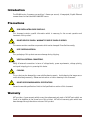
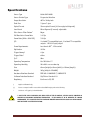
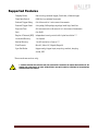
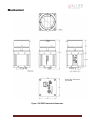
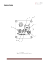
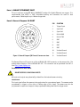
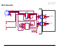
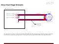
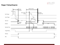
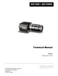
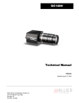
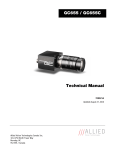
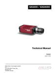
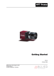
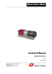
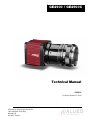
GE4900 / GE4900C
Technical Manual
700031A
Updated September 15, 2010
Allied Vision Technologies Canada Inc.
101-3750 North Fraser Way
Burnaby, BC
V5J 5E9 / Canada
Table of Contents
Table of Contents .......................................................................................................... ii
Introduction ............................................................................................................ 5
Precautions.............................................................................................................. 5
Warranty ................................................................................................................. 5
Specifications .......................................................................................................... 6
Supported Features ................................................................................................... 7
Mechanical .............................................................................................................. 8
Connections ............................................................................................................. 9
Cleaning the Sensor.................................................................................................. 14
Adjusting the F-mount .............................................................................................. 15
Camera Installation .................................................................................................. 17
System Optimization ................................................................................................. 22
Trouble Shooting ..................................................................................................... 24
Addendum .................................................................................................................. 27
GE IO Schematic ....................................................................................................... 28
Hirose 12-pin Trigger Schematic ................................................................................. 29
Mini-SMB Trigger Schematic ....................................................................................... 30
Trigger Timing Diagram ............................................................................................. 31
Notes on Triggering .................................................................................................. 32
GE4900 Technical Manual
Page 2
Legal notice
For customers in the U.S.A.
(FCC Compliance Information)
This equipment has been tested and found to comply with the limits for a Class A digital device, pursuant to Part 15 of the FCC Rules.
These limits are designed to provide reasonable protection against harmful interference when the equipment is operated in a
commercial environment. This equipment generates, uses, and can radiate radio frequency energy and, if not installed and used in
accordance with the instruction manual, may cause harmful interference to radio communications. However there is no guarantee
that interferences will not occur in a particular installation. Operation of this equipment in a residential environment is likely to
cause harmful interference.
You are cautioned that any changes or modifications not expressly approved in this manual could void your authority to operate this
equipment. The shielded interface cable recommended in this manual must be used with this equipment in order to comply with the
limits for a computing device pursuant to Subpart B of Part 15 of FCC Rules.
For customers in Canada
This digital apparatus complies with the Class A limits for radio noise emissions set out in the Radio Interference Regulations.
Pour utilisateurs au Canada
Cet appareil numérique est conforme aux normes classe A pour bruits radioélectriques, spécifiées dans le Règlement sur le
brouillage radioélectrique.
Life support applications
These products are not designed for use in life support appliances, devices, or systems where malfunction of these products can
reasonably be expected to result in personal injury. Allied Vision Technologies customers using or selling these products for use in
such applications do so at their own risk and agree to fully indemnify Allied Vision Technologies for any damages resulting from
such improper use or sale.
Trademarks
Unless stated otherwise, all trademarks appearing in this document are the property of Allied Vision Technologies and are fully
protected by law.
Warranty
The information provided by Allied Vision Technologies is supplied without any guarantees or warranty whatsoever, be it specific or
implicit. Also excluded are all implicit warranties concerning the negotiability, the suitability for specific applications or the nonbreaking of laws and patents. Even if we assume that the information supplied to us is accurate, errors and inaccuracy may still
occur.
Copyright
All text, pictures and graphics are protected by copyright and other laws protecting intellectual property. It is not permitted to copy
or modify them for trade use or transfer, nor may they be used on web sites.
Allied Vision Technologies Canada Inc. 1/2010
All rights reserved.
GE4900 Technical Manual
Page 3
Contacting Allied Vision Technologies
• Technical information:
http://www.alliedvisiontec.com
• Support:
[email protected]
Allied Vision Technologies GmbH (Headquarters)
Taschenweg 2a
07646 Stadtroda, Germany
Tel.: +49.36428.677-0
Fax.: +49.36428.677-28
e-mail: [email protected]
Allied Vision Technologies Canada Inc.
101-3750 North Fraser Way
Burnaby, BC, V5J 5E9, Canada
Tel: +1 604-875-8855
Fax: +1 604-875-8856
e-mail: [email protected]
Allied Vision Technologies Inc.
38 Washington Street
Newburyport, MA 01950, USA
Toll Free number +1-877-USA-1394
Tel.: +1 978-225-2030
Fax: +1 978-225-2029
e-mail: [email protected]
GE4900 Technical Manual
Page 4
Introduction
The GE4900 series of cameras are sensitive, 3 frames per second, 16 megapixel, Gigabit Ethernet
cameras based on the Kodak KAI-16000 CCD sensor.
Precautions
READ INSTALLATION GUIDE CAREFULLY.
This document contains specific information which is necessary for the correct operation and
treatment of this product.
DO NOT OPEN THE CAMERA. WARRANTY IS VOID IF CAMERA IS OPENED.
This camera contains sensitive components which can be damaged if handled incorrectly.
KEEP SHIPPING MATERIAL.
Poor packaging of this product can cause damage during shipping.
VERIFY ALL EXTERNAL CONNECTIONS.
Verify all external connections in terms of voltage levels, power requirements, voltage polarity,
and signal integrity prior to powering this device.
CLEANING.
This product can be damaged by some volatile cleaning agents. Avoid cleaning the image sensor
unless absolutely necessary. Please see instructions on sensor cleaning in this document.
DO NOT EXCEED ENVIRONMENTAL SPECIFICATIONS.
See environmental specifications limits in the Specifications section of this document.
Warranty
AVT provides a 2 year warranty which covers the replacement and repair of all AVT parts which are
found to be defective in the normal use of this product. AVT will not warranty parts which have
been damaged through the obvious misuse of this product.
GE4900 Technical Manual
Page 5
Specifications
Sensor Type
Kodak KAI-16000
Sensor Shutter Type
Progressive Interline
Image Resolution
4872 x 3248 pixels
Pixel Size
7.4μm x 7.4μm
Optical Format
35mm optical format (43.3mm physical diagonal )
Lens Mount
Nikon Bayonet (F-mount) -adjustable
Color Sensor Filter Pattern†
Bayer
Full Resolution Frame Rate
3.35 fps
Frame Rate (1024 x 1024 ROI)
7.04 fps
I/O
1 isolated TTL compatible input, 3 isolated TTL compatible
outputs. 1 RS-232 input/output.
Power Requirements
Less than 6.0W††. 12V nominal.
Digitization
12 Bits
Trigger latency*
4.2μs
Trigger Jitter*
±10ns
Tpd*
90ns
Operating Temperature
0 to 50 Celsius***
Operating Humidity
20 to 80% non-condensing
Size
66mm (height) x 66mm (width) x 110mm (length)
Weight
395g (406g for GE4900C)
Hardware Interface Standard
IEEE 802.3 1000BASE-T, 100BASE-TX
Software Interface Standard
GigE Vision Standard 1.0
Regulatory
Conforms to CE, FCC
†
Applies to GE4900C only.
††
Power consumption will increase with reduced ROI imaging and vertical binning.
*
See Notes on Triggering in the Addendum.
***DUE TO THE SMALL PACKAGING AND HIGH SPEED OF THE GE CAMERAS, SPECIAL CARE IS REQUIRED TO
MAINTAIN A REASONABLE OPERATING TEMPERATURE. IF THE CAMERA IS TO BE OPERATED IN A WARM
ENVIRONMENT, IT IS SUGGESTED THAT THE CAMERA BE MOUNTED ON A HEAT SINK SUCH AS A METAL BRACKET
AND THAT THERE IS SUFFICIENT AIR FLOW.
GE4900 Technical Manual
Page 6
Supported Features
Imaging Modes
free-running, external trigger, fixed rate, software trigger
Fixed Rate Control
0.001 fps to maximum frame rate
External Trigger Delay
0 to 60 seconds in 1 microsecond increments
External Trigger Event
rising edge, falling edge, any edge, level high, level low
Exposure Time
625 microseconds to 60 seconds in 1 microsecond increments
Gain
0 to 28dB
Region of Interest (ROI) independent x and y control with 1 pixel resolution***
Horizontal Binning
1 to 8 pixels
Vertical Binning
1 to full resolution of sensor***
Pixel Formats
Mono8*, Mono16*, Bayer8, Bayer16
Sync Out Modes
trigger ready, trigger input, exposing, readout, imaging,
strobe, GPO
*On monochrome versions only.
***VERTICAL BINNING AND VERTICAL ROI CAN SIGNIFICANTLY INCREASE THE POWER CONSUMPTION OF THE
CAMERA AND SHOULD ONLY BE USED INTERMITTENTLY AND WITH CAREFUL ATTENTION TO THE OPERATING
TEMPERATURE OF THE CAMERA.
GE4900 Technical Manual
Page 7
Mechanical
Figure 1. GE SERIES mechanical dimensions.
GE4900 Technical Manual
Page 8
Connections
5
6
1
2
7
3
4
Figure 2. GE SERIES connection diagram.
GE4900 Technical Manual
Page 9
Item 1: GIGABIT ETHERNET PORT
This port conforms to the IEEE 802.3 1000BASE-T standard for Gigabit Ethernet over copper. It is
recommended that CAT5E or CAT6 compatible cabling and connectors be used for best
performance. Cable lengths up to 100m are supported.
Item 2: General Purpose I/O PORT
9
8
12
7
6
1
10
11 2
3
5
4
Figure 3. General Purpose I/O Pin out. Camera rear view.
PIN
FUNCTION
1
Trigger Input
2
Sync Out 2
3
Sync Out 3
4
RS-232 RXD
5
RS-232 TXD
6
DNC
7
DNC
8
DNC
9
DNC
10
Isolated Ground
11
Isolated Ground
12
Isolated Ground
The General Purpose I/O port uses a Hirose HR10A-10R-12SB connector on the camera side. The
mating cable connector is Hirose HR10A-10P-12P. This connector can be purchased from AVT or
from http://www.digikey.com.
See Addendum for more detail.
DO NOT EXCEED 5.5V ON SIGNAL INPUTS.
All inputs and outputs are galvanically isolated from the internal camera circuitry.
TRIGGER INPUT
This input signal allows the camera to be synchronized to some external event. The camera can be
programmed to trigger on the rising or falling edge of this signal. The camera can also be
programmed to capture an image at some programmable delay time after the trigger event.
GE4900 Technical Manual
Page 10
Sync Out 2 and Sync Out 3
These signals only function as outputs and can be configured as follows:
Exposing
Corresponds to when camera is
integrating light.
Trigger Ready
Indicates when the camera will accept a
trigger signal.
Trigger Input
A relay of the trigger input signal used to
“daisy chain” the trigger signal for
multiple cameras.
Readout
Valid when camera is reading out data.
Strobe
Programmable pulse based on one of the
above events.
Imaging
Valid when camera is exposing or
reading out.
GPO
User programmable binary output.
Any of the above signals can be set for active high or active low.
RS-232 RXD and RS-232 TXD
These signals are RS-232 compatible. These signals allow communication from the host system via
the Ethernet port to a peripheral device connected to the camera.
ISOLATED GROUND
These signals are internally connected to isolated ground. At least one of these signals must be
connected to the users external circuit ground. However, it is good practice to provide a dedicated
ground return for each signal used. For example, a good cable design would connect the required
signal on one conductor of a twisted pair and the isolated ground on the second conductor of the
same twisted pair.
DNC
These signals are reserved for future use and should be left disconnected.
Item 3: Mini-SMB Trigger Input
The Mini-SMB port on the camera uses an Amphenol 903-406J-51R connector. A suitable mating
cable connector is Amp 413985-3 which can be used with RG174 coaxial cable. Contact AVT to
purchase cabling.
The Mini-SMB Trigger Input is internally connected to the Trigger Input (Pin 1) of the General
Purpose I/O Port (Item 2 above). Therefore see this section for more detail.
GE4900 Technical Manual
Page 11
Item 4: Mini-SMB Sync Out 1
This Mini-SMB port on the camera uses an Amphenol 903-406J-51R connector. A suitable mating
cable connector is Amp 413985-3 which can be used with RG174 coaxial cable. Contact AVT to
purchase cabling.
This connector is particularly useful for triggering multiple cameras in a “daisy chain” fashion.
The Sync Out 1 signal can be configured as follows:
Exposing
Corresponds to when camera is
integrating light.
Trigger Ready
Indicates when the camera will accept a
trigger signal.
Trigger Input
A relay of the trigger input signal used to
“daisy chain” the trigger signal for
multiple cameras.
Readout
Valid when camera is reading out data.
Strobe
Programmable pulse based on one of the
above events.
Imaging
Valid when camera is exposing or
reading out.
GPO
User programmable binary output.
Any of the above signals can be set for active high or active low.
Item 5: Status LED 1
LED COLOR
STATUS
Solid Green
Ethernet link established.
Flashing Green
Ethernet activity.
Item 6: Status LED 2
LED COLOR
STATUS
Solid Green
Normal operation.
Solid Orange
Firmware missing.
Flashing Orange
Camera fault.
GE4900 Technical Manual
Page 12
Item 7: AUXILIARY POWER PORT
This port is required to provide power to the camera.
This port provides threaded captivation of the power cable if required. The captivated cable
mating connector is the Switchcraft 760K. This connector can be purchased from AVT or from
http://www.digikey.com.
Cameras designated as “A”, with serial number 02-2xxxA-xxxxx can accept an input voltage range
of 5V to 17V DC.
Cameras designated as “C”, with serial numbers 02-2xxxC-xxxxx and later versions can accept an
input voltage range of 5V to 24V DC.
However the suggested nominal voltage is 12V and cameras are tested at 12V.
Cameras will normally include a power supply. However compatible power supplies can also be
ordered separately from AVT (AVT P/N 02-8000A for North America or AVT P/N 02-8001A for a
Universal supply). The inner conductor is positive power and the external conductor is ground.
THE CAMERA POWER SUPPLY OPERATES MOST EFFICIENTLY AT 12V.
GE4900 Technical Manual
Page 13
Cleaning the Sensor
DO NOT CONTACT CLEAN SENSOR UNLESS ABSOLUTELY NECESSARY.
Identifying Debris
Debris on the image sensor or optical components will appear as a darkened area or smudge on the
image that does not move as the camera is moved. Do not confuse this with a pixel defect which
will appear as a distinct point.
Locating Debris
Before attempting to clean the image sensor, it is important to first determine that the problem is
due to debris on the sensor window. To do this you should be viewing a uniform image, such as a
piece of paper, with the camera. Debris will appear as a dark spot or dark region that does not
move as the camera is moved. To determine that the debris is not on the camera lens, rotate the
lens independent of the camera. If the spot moves as the lens moves, then the object is on the
lens -not on the image sensor- and therefore cleaning is not required. If the camera has an IR
filter, then rotate the IR filter. If the object moves then the particle is on the IR filter not the
sensor. If this is the case remove the IR filter carefully using a 2.5mm hex wrench. Clean both
sides of the IR filter using the same techniques as explained below for the sensor window.
DO NOT TOUCH ANY OPTICS WITH FINGERS. OIL FROM FINGERS CAN DAMAGE FRAGILE
OPTICAL COATINGS.
Cleaning with Air
If it is determined that debris is on the sensor window, then remove the camera lens, and blow the
sensor window directly with clean compressed air. If canned air is used, do not shake or tilt the
can prior to blowing the sensor. View a live image with the camera after blowing. If the debris is
still there, repeat this process. Repeat the process a number of times with increased intensity until
it is determined that the particulate cannot be dislodged. If this is the case then proceed to the
contact cleaning technique.
Contact Cleaning
Only use this method as a last resort. Use 99% laboratory quality isopropyl alcohol and clean
cotton swabs. Dampen the swab in the alcohol and gently wipe the sensor in a single stroke. Do
not reuse the same swab. Do not wipe the sensor if the sensor and swab are both dry. You must
wipe the sensor quickly after immersion in the alcohol, or glue from the swab will contaminate the
sensor window. Repeat this process until the debris is gone. If this process fails to remove the
debris, then contact AVT.
GE4900 Technical Manual
Page 14
Adjusting the F-mount
SET SCREW
3 PLCS TYP
F MOUNT
FRONT ASSEMBLY
Figure 4. Camera Front View.
THE F-MOUNT IS ADJUSTED AT THE FACTORY AND SHOULD NOT REQUIRE ADJUSTING.
If for some reason, the F-mount requires adjustment, use the following method.
Attach F-mount compatible lens
Use an F-mount compatible lens that allows an infinity focus. Attach the lens to the camera using
a counter-clockwise rotation of about a quarter turn. The lens should snap into place and the lens
flange and camera flange should mate over the full circumference.
GE4900 Technical Manual
Page 15
Loosen F-MOUNT FRONT ASSEMBLY
Use a 1.5mm hex wrench to loosen the 3 set screws which hold the F-mount front assembly to the
camera body.
Image to Infinity
Set the lens to infinity and image a distant object. The distance required will depend on the lens
used but typically 30 to 50 feet should suffice. Gently move the F-mount front assembly until the
image is in focus. Carefully tighten the 3 set screws. Recheck the focus.
GE4900 Technical Manual
Page 16
Camera Installation
Computer Interface
The Prosilica GE Series cameras will work with any Gigabit Ethernet network card; however AVT
strongly recommends using Gigabit Ethernet components that support Jumbo Frames. A Jumbo
Frame is loosely defined as a frame size greater than 1500 bytes however typical Jumbo Frames are
around 9000 bytes. Frame size is the number of bytes per packet and the larger the frame size, the
less the computer CPU will be loaded due to the processing of incoming packets.
There are many Gigabit Ethernet cards available which will support Jumbo Frames. The following
examples have been verified to work well with the Prosilica GE cameras:
•
Intel PRO/1000
•
D-Link DGE-550T
•
SMC EZ Card 1000
Gigabit Ethernet cards supporting this feature can also be purchased with the camera (AVT P/N 023002A).
GE4900 Technical Manual
Page 17
Gigabit Ethernet Setup for Windows
o Install network card in computer.
o Boot the PC and cancel the “Found new Hardware Wizard” window that may appear when
Windows detects the new card.
o Install the driver that came with the network card.
o Once the driver is installed, open the Network Connections Dialog as follows: From the
Windows desktop select start, then select Control Panel, then double click on the Network
Connections icon. Double click the relevant network card listed or right-click the relevant
network card and select Properties. This will open the properties window for your network
card. See Figure 5.
Figure 5. Network card main properties window.
o Select the Internet Protocol (TCP/IP) check box and then select Properties. See Figure 6.
Network card TCP/IP address.. Select the Use the following IP address and enter an IP address
of 169. 254. x. y, where x and y can be any number. Press the TAB key after entering the IP
address and the subnet mask will automatically be entered. The subnet mask is 255. 255. 0. 0.
Click OK to save changes. Note that if Windows reports a conflict with the above IP address,
simply repeat the above steps and change the last digit of the IP address to a different value.
GE4900 Technical Manual
Page 18
Figure 6. Network card TCP/IP address.
Figure 7. Turn off Firewall.
o Return to the Gige Local Properties window as in Figure 5. Select the Advanced tab as in Figure
7 and disable the Firewall for this device. Click OK to save changes.
GE4900 Technical Manual
Page 19
Gigabit Ethernet Cabling
All Gigabit Ethernet cabling and connectors should be CAT5E or CAT6 compatible. Cable lengths
must not exceed 100 meters.
Power Connection
The camera requires a 12V DC power supply that can source a minimum of 600 mA of current. See
the Connections section of this document for more information.
Other Cabling
The camera can be triggered either through the 12 pin general purpose connector or the mini-SMB
input. The compatible cable connectors are specified in the Connections section of this document
or contact AVT to purchase compatible cabling. AVT provides SMB-to-SMB or SMB-to-BNC cabling
of varying lengths.
GE4900 Technical Manual
Page 20
Installing GigE Viewer for Testing
o The latest Viewer software can be downloaded from
http://www.alliedvisiontec.com/us/support.html.
o Run the GigE Viewer Installer.exe. This will install the AVT Digital Camera drivers as well as the
AVT GigE Viewer application program.
o Plug in the Prosilica GE camera via the Gigabit Ethernet port. Plug in the power connection.
Verify that the Status LED 1 is a solid green. Run the AVT GigE Viewer Application. It will take a
few seconds for the camera to be recognized. If the camera does not appear in the Viewer list
after approximately 10 seconds then try disconnecting and reconnecting the power. If it still
does not appear restart the viewer. If it still does not appear, see the Trouble Shooting section
of this document.
o See Figure 8. Select the wrench icon to change camera settings. Change the PacketSize to a
value of 1500. Select the eye icon to image. The camera should now be imaging. If the
camera is not imaging, see the Trouble Shooting section of this document. Note that the
PacketSize can be set to 8228 if the network card has been optimized to support jumbo frames.
o See the System Optimization Section to maximize the performance of your system.
Figure 8. GigE Viewer application window.
GE4900 Technical Manual
Page 21
System Optimization
o Open the Network Connections Dialog as follows: From the Windows desktop select start, then
select Control Panel, then double click on the Network Connections icon. Double click the
relevant network card listed or right-click the relevant network card and select Properties.
This will open the properties window for your network card. See Figure 9.
Figure 9. Network card main properties window.
o From the Properties window select Configure then select the Advanced tab. See Figure 10.
GE4900 Technical Manual
Page 22
Figure 10. Network card advanced settings.
o Set Maximum Frame Size or Jumbo Frames to the maximum possible value. A typical value is
9000. If the list contains a property called Receive Descriptors, then change this value to its
maximum value. Select OK to save properties.
o From the main properties dialog as in Figure 9, make sure that only the Internet Protocol
(TCP/IP) check box is selected then click OK. The card is now optimized for use with the
Prosilica GE camera.
o Open the viewer and set the PacketSize to 8228.
GE4900 Technical Manual
Page 23
Trouble Shooting
Is the camera getting power?
The right LED is the camera power indicator. If unlit, check the power adaptor. If possible, swap
with one that is known to work. If using a custom power adaptor, be sure the adaptor and wire
gauge is rated to at least 500 mA. If the right LED still does not light up, contact AVT support.
Is the camera powered, but not detected in SampleViewer?
Damaged or poor quality Ethernet cabling can result in no cameras found, dropped packets,
decreased bandwidth, and other problems. Use Cat5e or better cabling known to work.
Configure your NIC as outlined in “Gigabit Ethernet Setup For Windows”. It should have an IP
address of 169.254.x.x, Subnet Mask: 255.255.0.0. This is the AutoIP address range. If your NIC
has no access to a DHCP server, the camera will still be auto assigned an IP address. There should
be no gateway on your NIC.
Connect a single camera directly to your NIC, no hub/switch, and run the AVT IP Configuration
utility (Start>Programs>AVT>GigEIPConfig or C:\Program Files\AVT\GigEViewer\ipconfig.exe). You
may need to wait up to 30 sec for camera to appear.
A camera in DHCP (AutoIP fallback) mode.
•
Camera is listed: Your camera and NIC must be on the same subnet, e.g.: NIC: IP
169.254.23.2 Subnet Mask: 255.255.0.0, Camera IP: 169.254.43.3 Subnet Mask: 255.255.0.0.
The following example is not on the same Subnet: NIC IP 169.250.23.2 Subnet Mask:
255.255.255.0, CamIP 169.254.13.0 Subnet Mask: 255.255.0.0. This can happen if you use a non
AutoIP range on your NIC and it doesn’t have access to a DHCP server. Either change your NIC IP to
be in the AutoIP range, or fix the camera IP address to be on the same subnet as your NIC.
GE4900 Technical Manual
Page 24
•
Camera is not listed, or flashing “Camera Unavailable”: There may be multiple NICs on your
system set to the same subnet. The camera can not know which card to resolve to. Change the IP
address of your NIC.
If you are still having problems, type: ipconfig /all in a windows command prompt, and send a
screenshot to [email protected].
Ipconfig /all screenshot
Is the camera listed in SampleViewer but can’t acquire images?
Reset your camera settings to factory default: with ConfigFileIndex = Factory, click the
ConfigFileLoad button.
While streaming, check your Stats:
GE4900 Technical Manual
Page 25
All stats 0 while streaming. Firewall likely blocking traffic
•
•
•
All stats 0. Likely a firewall is blocking incoming traffic. Disable your firewall. Check your camera
trigger settings. Many camera trigger modes require a software or hardware trigger event to
capture frames.
Packets are incoming, but all dropping. Be sure you have JumboFrames enabled on your NIC.
Otherwise, decrease your PacketSize setting to 1500.
All packets completing as normal, but black image. Check ExposureValue, ExposureMode, and be
sure your scene is suitably lit.
If you are still having problems acquiring images, please send your camera settings file (click on the
disk icon in SampleViewer) to [email protected].
Saving camera setting file
GE4900 Technical Manual
Page 26
Addendum
GE4900 Technical Manual
Page 27
GE IO Schematic
HIROSE HR10A-10R-12SB
9
1
10
8
2
7
3
6
12
11
CAMERA INTERNAL CIRCUIT
1
2
3
4
5
6
7
8
9
10
11
12
4
5
TRIGGER INPUT
SY NC OUT 2
SY NC OUT 3
RS-232 RXD
RS-232 TXD
18
16
14
12
SY NC OUT 3
SY NC OUT 2
SY NC OUT 1
TEXAS INSTRUMENTS
SN74ACT244PWR
2
1Y 1
1A1 4
1Y 2
1A2 6
1Y 3
1A3 8
1Y 4
1A4
9
7
5
3
AS SEEN FROM
CAMERA REAR
VIEW
2Y 1
2Y 2
2Y 3
2Y 4
2A1
2A2
2A3
2A4
1OE
2OE
VCC
GND
11
13
15
17
16
15
14
13
12
11
10
9
ISO+5V
1
19
20
10
ISO_+5V
MINI-SMB
VDD-3.3
VDD2
GND2
OUT1
OUT2
IN3
IN4
NC
GND2
VDD1
GND1
IN1
IN2
OUT3
OUT4
NC
GND1
1
2
3
4
5
6
7
8
NVE
IL716-3
ISO+5V
TRIGGER INPUT
IN
LOGIC SY NC OUT 1
LOGIC SY NC OUT 2
LOGIC TRIGGER INPUT
VDD-3.3
ISO+5V
MAXIM
MAX3221CPWR
1
0.1u
2
0.1u
3
4
0.1u
5
MINI-SMB
OUT
NVE
IL716-3
ISO+5V
TRIGGER INPUT
SY NC OUT 1
6
0.1u
7
8
EN
C1+
FORCEOFF
VCC
V+
GND
C1-
DOUT
C2+
FORCEON
C2-
DIN
VRIN
INVALID
ROUT
16
15
14
13
12
11
10
9
16
15
14
13
RS232-TXD
VDD2
GND2
OUT1
OUT2
IN3
IN4
NC
GND2
12
11
ISO TXD
10
9
ISO RXD
ISO+5V
RS232-RXD
ISOLATED 5V POWER
ISOLATED GROUND
GALVANIC
ISOLATION
BOUNDARY
GE4900 Technical Manual
Page 28
VDD1
GND1
IN1
IN2
OUT3
OUT4
NC
GND1
1
2
3
4
5
6
7
8
LOGIC SY NC OUT 3
LOGIC TXD
LOGIC RXD
Hirose 12-pin Trigger Schematic
USERS TRIGGER CIRCUIT
CABLE SIDE
USER TRIGGER (5V TTL DRIVER)
TRIGGER INPUT
SY NC OUT 2
SY NC OUT 3
SY NC OUT 2 (5V TTL RECEIVER)
SY NC OUT 3 (5V TTL RECEIVER)
1
2
3
4
5
6
7
8
9
10
11
12
1
9
10
2
8
3
7
4
11
12
6
5
HIROSE HR10A-10P-12P
ONE GROUND
RETURN IS
SUFFICIENT.
The trigger circuit is connected to a Texas Instruments SN74ACT244PWR buffer/driver inside the camera. The required trigger input current is
less than 10uA and the maximum sync output current is 24mA. See the Texas Instruments SN74ACT244PWR for more detailed information.
GE4900 Technical Manual
Page 29
Mini-SMB Trigger Schematic
USERS TRIGGER CIRCUIT
RG-174 COAX CABLE
MINI-SMB
TRIGGER INPUT
USER TRIGGER (5V TTL DRIVER)
IN
RG-174 COAX CABLE
MINI-SMB
SY NC OUT 1
SY NC OUT 1 (5V TTL RECEIVER)
OUT
The trigger circuit is connected to a Texas Instruments SN74ACT244PWR buffer/driver inside the camera. The required trigger input current is
less than 10uA and the maximum sync output current is 24mA. See the Texas Instruments SN74ACT244PWR for more detailed information.
Note that the trigger input signal is not terminated to match the cable impedance.
GE4900 Technical Manual
Page 30
Trigger Timing Diagram
Readout Time
Trigger
Latency
Tpd
User Trigger
Expose Start
Delay
Registered
Exposure Time
Logic Trigger
Exposure
Readout
N
Trigger
Jitter
N+1
N
N+1
Interline Time
Trigger Ready
Imaging
Idle
GE4900 Technical Manual
Page 31
Notes on Triggering
Definitions
o User Trigger is the trigger signal applied by the user.
o Logic Trigger is the trigger signal seen by the camera internal logic.
o Tpd is the propagation delay between the User Trigger and the Logic Trigger.
o Exposure is high when the camera image sensor is integrating light.
o Readout is high when the camera image sensor is reading out data.
o Trigger Latency is the time delay between the User Trigger and the start of Exposure.
o Trigger Jitter is the error in the Trigger Latency time.
o Trigger Ready indicates to the user that the camera will accept the next trigger.
o Registered Exposure Time is the Exposure Time value currently stored in the camera memory.
o Expose Start Delay is the delay time from the start of Exposure to valid Trigger Ready. It is the
Registered Exposure Time subtracted from the Readout time and indicates when the next
Exposure cycle can begin such that the Exposure will end after the current Readout.
o Interline Time is the time between sensor row readout cycles.
o Imaging is high when the camera image sensor is either exposing and/or reading out data.
o Idle is high if the camera image sensor is not exposing and/or reading out data.
Rules
o The User Trigger pulse width should be at least three times the width of the Trigger Latency as
indicated in the Specifications section of this document.
o The end of Exposure will always trigger the next Readout.
o The end of Exposure must always end after the current Readout.
o The start of Exposure must always correspond with the Interline Time if Readout is true.
o Expose Start Delay equals the Readout time minus the Registered Exposure Time.
Triggering during the Idle State
o For applications requiring the shortest possible Trigger Latency and the smallest possible
Trigger Jitter the User Trigger signal should be applied when Imaging is false and Idle is true.
o In this case, Trigger Latency and Trigger Jitter are as indicated in the Specifications section.
GE4900 Technical Manual
Page 32
Triggering during the Readout State
o For applications requiring the fastest triggering cycle time whereby the camera image sensor is
exposing and reading out simultaneously, then the User Trigger signal should be applied as
soon as a valid Trigger Ready is detected.
o In this case, Trigger Latency and Trigger Jitter can be up to 1 line time since Exposure must
always begin on an Interline boundary.
GE4900 Technical Manual
Page 33