1
TM
MODULAR INPUT DEVICE™
USER'S MANUAL
MID – UMANGB06
Rev. 6, November 2000
Covers MIDWIN ver. 3.0.7
and higher!
BLANK
CONTENTS
Page i
Contents:
1. DESCRIBING MID............................................. 1
1.1. WHERE TO USE MID ..................................................................... 4
1.2. HOW TO INSTALL MID .................................................................. 4
2. ASSEMBLING AND CONNECTING ................. 5
2.1. ASSEMBLING MID CONFIGURATION ......................................... 5
2.2. CONNECTING MID......................................................................... 7
2.2.1. CONNECTING THE MID TO THE AT/PS2 PORT ONLY ...................... 8
2.2.2. CONNECTING THE MID TO THE AT/PS2 AND RS232 PORT .............. 8
2.2.3. CONNECTING THE MID TO THE RS232 PORT ONLY ....................... 9
2.3. CONNECTING EXTERNAL MID MODULES ............................... 11
2.4. CONNECTING THE BARCODE SCANNER................................ 12
3. PROGRAMMING THE KEYBOARD............... 13
3.1. PROGRAM INSTALLATION ........................................................ 13
3.2. RUNNING THE PROGRAM.......................................................... 13
3.3. PROGRAMMING KEYBOARD – FLOW CHART .......................... 15
3.4. ARRANGING THE KEYBOARD .................................................. 16
3.4.1. SELF-RECOGNISING ................................................................... 16
3.4.2. ADDING MODULES ..................................................................... 17
3.4.3. DELETING MODULES .................................................................. 17
3.4.4. DELETING CONFIGURATION ....................................................... 18
3.4.5. SAVING CONFIGURATION ........................................................... 18
3.4.6. OPENING EXISTING CONFIGURATION ......................................... 18
3.5. KEYBOARD SETTINGS............................................................... 18
3.6. EDIT OPTIONS ............................................................................. 20
3.7. SELECTING COMMUNICATION PORT ...................................... 21
3.8. SETTING THE MATRIX MODULES............................................. 21
3.8.1. WRITING DEFAULT KEY CONFIGURATIONS ...................................... 21
3.8.2. KEY CONFIGURATION INPUT ............................................................... 22
3.9. SETTING UP ADDITIONAL MODULES....................................... 27
3.9.1. MAGNETIC CARD READER .......................................................... 27
3.9.2. MATRIX MODULES WITH INTEGRATED KEYLOCK ........................ 28
3.9.3. MATRIX MODULES WITH INTEGRATED LCD................................. 29
3.9.4. MATRIX MODULE WITH INTEGRATED SMART CARD READER....... 30
3.9.5. MATRIX MODULE WITH INTEGRATED IDENTIFICATION BUTTON
READER (IBUTTON) ............................................................................. 32
3.9.6. BAR CODE READER (BCR) .......................................................... 33
3.10. SAVING THE KEYBOARD CONTENTS .................................... 36
MID - USER'S MANUAL
Page ii
CONTENTS
3.11. IMPORT / EXPORT KEY CONTENTS ....................................... 36
3.11.1. MID EXPORT TEXT FILE FORMAT .............................................. 37
3.12. PROGRAM VERSION ................................................................ 38
4. KEYBOARD FEATURES ................................ 39
4.1. PROGRAMMING THE KEYBOARD ............................................ 39
4.2. TESTING THE KEYBOARD ......................................................... 39
4.2.1. TESTING THE RS232 KEYBOARD................................................. 39
4.3. UPLOADING THE KEYBOARD ................................................... 40
4.4. KEYBOARD INFORMATION ....................................................... 40
4.5. ROLLOVER................................................................................... 41
4.5.1. WHAT IS ROLLOVER ................................................................... 41
4.5.2. WHAT TO DO IF A ROLLOVER OCCURS ....................................... 43
5. OTHER UTILITIES .......................................... 44
5.1. PRINTING KEY LABELS ............................................................. 44
5.2. MID API ......................................................................................... 46
6. TECHNICAL DATA ......................................... 47
6.1. KEYBOARD FEATURES ............................................................. 47
6.2. TECHNICAL DATA....................................................................... 47
6.3. ASCII CHARACTER SET ............................................................. 48
6.4. SPECIFICATION OF THE SERIAL COMMUNICATION ............ 49
6.5. KEYBOARD MODULES............................................................... 49
6.5.1. FULL TRAVEL KEYBOARD MODULES ........................................... 49
6.5.2. SHORT TRAVEL KEYBOARD MODULES ....................................... 50
6.5.3. INTEGRATED IBUTTON MODULE ................................................. 51
6.6. MCR MODULES ........................................................................... 51
6.7. IC CARD READER MODULES (ICCR)........................................ 52
6.8. BAR CODE SLOT READER (BCR) ............................................. 53
6.9. ACCESSORIES ............................................................................ 53
6.10. ORDERING CODES ................................................................... 53
7. COPYRIGHTS AND
TECHNICAL SUPPORT ........................... 54
MID - USER'S MANUAL
SETTING UP THE KEYBOARD
Page 1
1. Describing MID
The MID is a new concept of programmable keyboard, offering a
solution for the ever changing needs of retailers, VARs, OEMs and POS
software developers. MID is a modular input device, which brings ‘plug
and play’to the level of programmable keyboards.
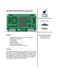
MID is build around a master module (Figure 1) that controls
programming,
communication
between
MID
modules
and
communication with the computer. It can control up to 14 modules with a
maximum of 256 keys. Non-volatile memory (EEPROM) stores all the
programmed data for the keyboard, making it independent of the
computer and its operating system.
For more demanding systems, there is a master module which can
simultaneously communicate via the keyboard port (AT/PS2) and the
RS232 interface, enabling users to choose the mode of communication
for each connected device. It is also possible for one key to send data to
the keyboard port, while the next one communicates via RS232.
Figure 1: The Master module
MID - USER'S MANUAL
Page 2
SETTING UP THE KEYBOARD
Modules are available with various numbers of keys (32 to 128) with a
choice of input and output devices that can be combined to create a
keyboard to meet customer’s immediate and future needs.
Simple connection of additional modules, user friendly software that
automatically recognises the attached configuration and enables
programming of each module, a utility for printing labels and many other
features distinguish MID from other programmable keyboards designed
for POS and similar applications.
Keyboard modules with 32, 64, 96 and 128 keys are available in full
travel and sealed short travel (membrane protected) variants, plus
modules with a combination of alphanumeric (qwerty) and
programmable keys. Both keyboard types use mechanical switches
mounted on the rigid metal carrying plate for strength and durability.
In addition, the full travel modules are available also with integrated
keylock, iButton and/or LCD. The first two, which can be integrated in
the upper right-hand corner of a module are used for identification
purposes, while the built-in LCD with 2x20 characters makes the
keyboard ideal for applications requiring space saving.
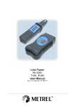
BOTTOM LID
KEY MATRIX ,
CASE IN PROFILE
KEY MATRIX
LED DIODES , LABELS HERE
- cover
- keycap
Figure 2: Keyboard modules
MID - USER'S MANUAL
SETTING UP THE KEYBOARD
Page 3
For electric funds transfer, identification and secure data entry, there are:
• Magnetic card reader (MCR; two and three track readers),
• Bar code slot reader (BCR) and
• Smart card reader/writer modules (ICCR).
Figure 3: Magnetic card readers
and bar code slot reader share the
same housing
Figure 4: Smart card reader
(ICCR)
Software allows programming of each key in four layers (four functions
per key) as well as programming of other modules (MCR, BCR, keylock,
iButton… ).
Definition of each key in each layer can include:
• Any key function of a standard keyboard,
• Combination of simultaneously pressed keys,
• Inter character delay and beep,
• Auto repeat function and click tone, when the key is pressed.
Label printing utility, connected to the software for programming the
keyboard, enables preparing, formatting and printing of labels for
programmed keys, giving a professional look to the keyboard.
MID - USER'S MANUAL
Page 4
SETTING UP THE KEYBOARD
1.1. Where to use MID
MID is a programmable keyboard where keys can represent
• A sequence of codes (e.g. SOLUTION)
• A combination of standard keys (e.g. CTRL-F11)
• Or combination of both.
This makes the MID ideal to be used in
• POS, where every key means an item
• Special office applications, where every programmable key replaces
a combination of keys or mouse action (e.g. CAD, managers or
bookkeeping programs… )
• Dedicated applications, where very few commands are needed or
where low introduction time is essential (e.g. telephone exchange,
label printers, industrial machines… ).
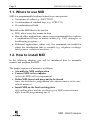
1.2. How to install MID
In the following chapters you will be introduced how to assemble,
connect and program the MID.
The proper sequence of actions is as follows:
• Assemble the MID configuration
• Connect MID to the computer
(where the MID will be programmed)
• Define MID layout and program the keyboard
(once the keyboard is programmed the content remains in the nonvolatile memory)
• Install MID on the final working place
(the working place and the working type of MID connection may
differ from the programming one’s).
MID - USER'S MANUAL
SETTING UP THE KEYBOARD
Page 5
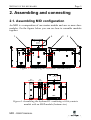
2. Assembling and connecting
2.1. Assembling MID configuration
An MID is a composition of one master module and one or more slave
modules. On the figures below you can see how to assemble modules
together.
4
3
2
5
MASTER
MODULE
Figure 5: Assembling the keyboard I (bottom view)
MASTE R
MCR
B OTOM PLATE
MCR
HOUSING
M
R
L
R
R
M
MATRIX
064
Figure 6: Assembling the keyboard II: combining a 64-key matrix
module with an MCR module (bottom view)
MID - USER'S MANUAL
Page 6
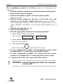
SETTING UP THE KEYBOARD
The assembling procedure is as follows (steps are indicated on the
Figure 5):
1. Turn the modules upside down and dismount the bottom plates
2. Insert joiners between modules
3. Connect all modules together with short ribbon cables
(connectors L-R)
4. Slip the master modules in the place of the back cover and
connect it to the module’s middle connector (connectors M-M)
If the configuration consists of more than one keyboard module (in our
example KM064A and KM096A) you may connect master module in any of
them.
5. Add left and right side covers
6. Fasten the bottom plates
7. Stick the appropriate labels on the keyboard modules:
• where master module is inserted:
PLACE LABELS L1 L2 L3 L4 AND Num Caps Scroll !
Lock
Lock
Lock
• where master module is NOT inserted:
PLACE BLANK LABELS!
• with integrated keylock:
AROUND THE KEYLOCK!
PLACE THE LABEL
8. If your configuration includes external modules connect them
as explained in 2.3 Connecting external MID modules.
9. If your configuration includes an external barcode scanner
connect it as explained in 2.4 Connecting the barcode scanner.
10. Keyboard is ready to be connected to the system.
!
WARNING: connect the keyboard when the computer
is turned off!
MID - USER'S MANUAL
SETTING UP THE KEYBOARD
Page 7
2.2. Connecting MID
There are three ways how to connect MID to the system or with different
words, three different working modes:
1. MID uses AT/PS2 primary interface only – this is typical when
MID consists mostly of input modules (e.g. key modules, MCR,
iButton… ). Communication with output modules is also possible,
just somehow slower.
2. MID communicates simultaneously via both AT/PS2 and RS232
primary interfaces - this operating mode is typical when MID is
composed of both input (e.g. key modules, MCR, iButton… ) and
output modules (e.g. LCD, ICCR… ).
3. MID communicates via RS232 primary interface only – this
solution is suitable wherever only RS232 communication port is
available.
i
MID modules sending data towards the host system
are referred as INPUT modules (as seen from the host
side), while modules receiving data form the host are
referred as OUTPUT modules.
But, before explaining in details all three operating modes, get us first
familiar with the connectors that are available on the rear side of the
master module.
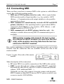
Figure 7 (right): Rear side of the master
module
Short description of the connectors:
• PC (mini DIN 8) is used for connection of the MID to the system.
• KBD is a pass through port, where a standard IBM PC compatible
keyboard any other device with PS/2 could be connected (barcode
scanner, OCR, additional MID… ).
Optionally you may also connect a barcode scanner with decoded
RS232 output or other RS232 device (RS232 option available only
on master models MID-MR0Bx).
MID - USER'S MANUAL
Page 8
SETTING UP THE KEYBOARD
• Optional EXT connector is used for connection of an external MID
module (available only on master models MID-MxxxC).
2.2.1. Connecting the MID to the AT/PS2 port only
These types of applications are based on the communication in the
direction from the keyboard to the system. The keyboard is composed of
input modules (e.g. key modules, keylock, iButton, MCR, BCR) and is
connected to the system’s keyboard port (called also AT or PS/2 port –
port where normally a standard keyboard is connected).
This port on the PC has been designed basically as input interface that is
very suitable for collecting data coming from the human driven
peripherals, and less suitable (rather slow) for sending data from the
system toward ‘throughput hungry’peripherals.
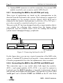
PC computer
PC
KBD
Master module
Module 1
Module 2
Module 14
PC keyboard
Figure 8: Connecting keyboard to the PC
On the figure above you can see a typical connection of the MID to the
system. A standard PC keyboard is not needed – it may remain connected
if besides programmable keys also fast alphanumeric entry is needed.
2.2.2. Connecting the MID to the AT/PS2 and RS232 port
This connection type is very useful, where both input (key modules,
MCR… ) and output modules (LCD, ICCR… ) are used. In contrast to
keyboard port the RS232 interface is basically bi-directional channel
and provides much higher data throughput. This interface is in also called
‘serial port’ and is labelled COM1 and COM2 on the PC side. Both
MID - USER'S MANUAL
SETTING UP THE KEYBOARD
Page 9
interfaces can be used simultaneously.
It is advisable to use input modules through the keyboard port (it is well
supported in operating system and is easy to capture incoming codes)
and communicate with output (e.g. LCD) and input/output modules
(e.g. ICCR) via the RS232, especially if the communication requires fast
and comprehensive data exchange.
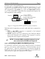
Computer
connector : DSUB 9
to: COM / RS 232 port
connector : DIN 5 or mini DIN 6
to: keyboard connector
MID keyboard
Figure 9: Using both AT/PS2 and RS232 primary interfaces
With this kind of connection you need a split cable that is connected as
follows:
• DIN5 or mini DIN6 connector is connected to the keyboard
connector of the PC computer.
• DSUB9 connector has to be connected to the COM port (RS232
port) on the Terminal or PC computer. This connector is used for
sending data from computer to the keyboard.
F
NOTE: A standard IBM-compatible keyboard can be
also connected to the MID (see Figure 8)!
2.2.3. Connecting the MID to the RS232 port only
If a keyboard is connected to the system, which do not have a keyboard
port (e.g. cash registers, industrial printers, industrial machines, special
PC applications… ) then the communication is performed through the
RS232 port only. In this case the power supply has to be provided by an
additional power supply and using special cable adapter.
MID - USER'S MANUAL
Page 10
SETTING UP THE KEYBOARD
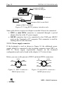
connector: D-SUB 9
to: COM / RS 232 port
MID keyboard
5V power supply
connector: DIN 5 or mini DIN 6
adapter to DIN 5 / mini DIN 6
Figure 10: Using RS232 primary interface only
Same split cable as in previous chapter is needed. It has to be connected:
• DIN5 or mini DIN6 connector is connected through a special
adapter directly to the 5V power supply.
• DSUB9 connector has to be connected to the COM port (RS232
port) on the Terminal or PC computer. This connector is used for
sending data in both directions.
2.2.3.1. Power supply connector
If the keyboard is used as shown in Figure 10, the additional power
supply should be connected to the keyboard connector (mini DIN 6 or
DIN 5). Power supply requirements depends on the keyboard
configuration and can be found in the chapter 6.2 Technical data.
Below you can see the pin-out of DIN 5 and mini DIN 6 connectors:
DATA
+5V
GND
2
5
NC
DATA
2
1
4
+5V
NC
CLOCK
3
1
SHIELD
Figure 11: DIN 5 connector MALE (front view)
NC
3
4
6
GND
CLOCK
SHIELD
5
Figure 12: mini DIN 6 connector –
MALE (front view)
MID - USER'S MANUAL
SETTING UP THE KEYBOARD
Page 11
2.2.3.2. D-SUB9 connector (RS232)
RS232 connection is provided through a standard female D-SUB9
connector, whose pin-out you can see on the following figure:
5
4
9
3
3
8
2
7
2 - TXD (kbd to system)
3 - RXD (system to kbd)
5 - GND
1
6
Figure 13: D-SUB 9 connector – FEMALE (front view)
2.3. Connecting external MID modules
An external MID module is derived from the corresponding regular MID
module by means of simple electromechanical modification where
additional 5-pin MINI DIN connector is added at the rear side of the
module. Modules that are available in external variants are: MCR, BCR,
ICCR and 32-key pin pad.
Using special cable (ord. code: MID-CEE) you can connect external
module to the connector EXT on the master module (see Figure 7). This
connector is integrated only on some variants of master module – master
modules with ord. code MID-Mx0xC.
PC computer
EXT
PC
Master module
Module 1
Module 2
Figure 14:External MID module connection
MID - USER'S MANUAL
Page 12
SETTING UP THE KEYBOARD
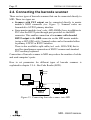
2.4. Connecting the barcode scanner
There are two types of barcode scanners that can be connected directly to
MID. These two types are:
• Scanners with PS/2 output can be connected directly to master
module’s KBD connector (see Figure 7). Scanned codes are
forwarded to AT/PS2 primary interface.
• Some master modules (ord. code: MID-MR0Bx) have in addition to
PS/2 also the RS232 pass through port provided via the KBD
connector. This enables connection of a scanner with decoded
RS232 output to the KBD connector on the MID master module
(using a MID-CBB cable). Scanned codes can be forwarded either
to primary AT/PS2 or RS232 interface.
There is also available a split cable (ord. code: MID-CKB) that is
used for simultaneous connection of RS232 scanner and standard
PS/2 auxiliary keyboard.
Connection of barcode scanner to MID may reduce the number of cables
and used computer’s ports.
How to set parameters for different types of barcode scanners is
explained in chapter 3.9.6 - Bar Code Reader (BCR).
Barcode
scanner
Adapter
PC computer
PC
KBD
MASTER
MID
PC keyboard
Figure 15: Connecting barcode scanner into MID
MID - USER'S MANUAL
SETTING UP THE KEYBOARD
Page 13
3. Programming the keyboard
3.1. Program installation
The software used to program the keyboard is on the supplied floppy
disc. There are two programs, MIDDOS and MIDWIN. The MIDDOS
program is used to program the keyboard under the MS-DOS operating
system. The MIDWIN program should be used in Windows 95/NT,
Windows NT and Windows 2000 environments.
Installing the program:
Insert the floppy disc into a 3.5-inch floppy disc drive.
• If you are using MS-DOS, run the file SETUPDOS (A:\SETUPDOS);
• In Windows, use the file SETUP (A:\SETUP).
SETUPDOS copies the contents of the floppy disc into the chosen
directory on the computer's hard disk. SETUPWIN copies the contents
into the chosen directory on the computer's hard disc and creates all
necessary icons.
3.2. Running the program
Programming, which is identical for both DOS and Windows
environments follows combining the keyboard.
The program is executed with the following commands:
• Under MS-DOS, change directory to the C:\TIPRO\MID then run the
program MIDDOS;
c:> CD c:\TIPRO\MID <ENTER>
c:> MIDDOS <ENTER>
• Under Windows, use the program MIDWIN (in the program group
Tipro keyboards);
MID - USER'S MANUAL
Page 14
SETTING UP THE KEYBOARD
F
NOTE: you shouldn’t run the MIDDOS program from
the DOS PROMPT in Windows environment!
You should exit Windows in pure DOS mode!
F
NOTE: this manual covers MIDWIN versions 3.0.7
(issued on September 04, 2000) and higher!
Some described functions may not be
available in previous versions!
MID - USER'S MANUAL
SETTING UP THE KEYBOARD
Page 15
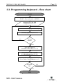
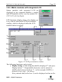
3.3. Programming keyboard – flow chart
START
Run MIDWIN
START->Tipro keyboards ->MIDWIN
Autodetection of the MID
configuration (see 3.4.1)
Press the desired programmable key
Set all key properties (see 3.8.2)
All keys
entered?
NO
YES
Save data in the file
Select File->Save (F2) (see 3.10)
Download data to the keyboard
Press Download button (see 4.1)
Test the keyboard
Select Tools->Text Window (see 4.2)
Keyboard
OK?
YES
END
MID - USER'S MANUAL
NO
Page 16
SETTING UP THE KEYBOARD
3.4. Arranging the keyboard
The configuration of the keyboard is detected automatically when the
MIDWIN is started. However, you may generate the keyboard also offline by adding and removing modules.
All functions that are explained in
this chapter can be found in the
menu group Desktop.
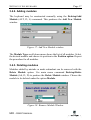
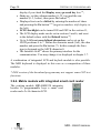
3.4.1. Self-recognising
The command Desktop/Auto detect (ALT, D, U) checks the
configuration of the connected MID keyboard and displays it in the main
window. This command is identical to pressing the Auto detect button
on the desktop. This procedure is executed automatically when MIDWIN
is started
Figure 16: Autodetecting the MID configuration
MID - USER'S MANUAL
SETTING UP THE KEYBOARD
Page 17
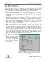
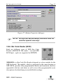
3.4.2. Adding modules
The keyboard may be constructed manually using the Desktop/Add
Module (ALT, D, A) command. This produces the Add New Module
window.
Figure 17: Add New Module window
The Module Type scroll down menu shows the list of all modules. Select
the desired module and choose its position in the Position option. Repeat
the procedure for all modules.
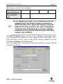
3.4.3. Deleting modules
Modules added by mistake or made redundant can be removed with the
Delete Module option. Use main menu command Desktop/Delete
Module (Alt, D, D) to produce the Delete Module window. Choose the
module to be deleted under the option Module.
Figure 18: Remove Module Window
MID - USER'S MANUAL
Page 18
SETTING UP THE KEYBOARD
3.4.4. Deleting configuration
All the modules of the keyboard can be deleted by the Clear Desktop
option. Choose the command Desktop->Clear Desktop (Alt, D, C) from
the main menu and the entire on-screen configuration will be deleted.
3.4.5. Saving configuration
Save the combined modules with the Save Desktop command. The
command Desktop->Save Desktop (Alt, D, S) opens the standard Save
dialogue; input the configuration's name and the desired saving location
here. The file extension for the MID configuration file is .mcf.
Note that only the names of the modules and their positions are stored in
the configuration file.
3.4.6. Opening existing configuration
Any completed configuration may be recalled with the Open Desktop
command. The menu option Desktop->Open Desktop (Alt, D, O) opens
the Open window where the location of the keyboard to be reconfigured
may be pinpointed.
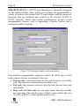
3.5. Keyboard settings
The basic keyboard options are set in the Settings window, and are
opened with the Keyboard->Settings (Alt, K, S) command.
The following options can be set:
•In the field Layout you must set which international standard keyboard
layout is used,
•By control element Number of layers is set how many separate
contents (layers) that can be set for each keyboard key,
•The ASCII control element selects how the ASCII data (ASCII key
content and magnetic card data) are sent to the PC computer. It can be
sent as keyboard scan codes (check Selected layout) or as Alt-ASCII
sequence (check Alt+NumPad);
MID - USER'S MANUAL
SETTING UP THE KEYBOARD
Page 19
•The keyboard can produce the sound every time a key is pressed (key
click function). There are two controls in this window used to set the
characteristics of the sound – tone and duration.
•By the global control element Click default it is set whether the key
click function for the whole keyboard is enabled (check ON) or
disabled (check OFF) on the keyboard reset. This option can be
combined with Click switch key (refer to 3.8.2 Key configuration
input), which enables and disables this function on-line (while
working). If the key click function is set to DEFAULT OFF, you can
turn it on by Click Switch key and vice-versa,
•If you use an RS232 MID keyboard you can select the RS232 Baud
rate of the keyboard. Default setting is 9600 Baud,
•MID keyboard may send codes too fast for some computers. In this
case you need to change the Interbyte delay setting that defines the
time difference between two consecutive sent codes (default is 1 ms).
The pre-set values are shown on the following figure:
Figure 19: Settings window
MID - USER'S MANUAL
Page 20
SETTING UP THE KEYBOARD
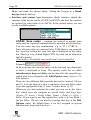
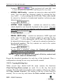
3.6. Edit options
The editor options (how the contents are entered) are set in the Edit
options window, which can be opened with the Options->Editor (Alt,
O, E) command or with the Editor options button on the desktop.
•With the Scan line exit key you may reserve one key that is used for
exiting the scan line (the field where the AT/PS2 Scan Codes are
captured).
•For RS232 or a special (not standard) AT/PS2 key content mode set the
Content edit mode option to Extended. When this option is checked,
keys contents can be inserted as standard AT/PS2, special AT/PS2 or
RS232 keys, while the Normal mode enables only standard AT/PS2
keys (refer to 3.8.2.2 Content keys).
•MID keyboard allows you to program a special beep or delay inbetween other codes. So called intercharacter beep and delay can be
entered with Delay 100 ms, Delay 1s and Beep keys that are defined
in this window. When a standard key is assigned a special function
(e.g. F10 = Delay 1s) every press of that key inserts a delay of 1 s. If
you would like to enter a F10 (original value) then the Delay 1s key
need to be reassigned to None or other possible key.
•In the control Fast
entry you can select
whether the Content 1
is copied to all the
other contents if they
are empty.
Figure 20: Edit options window with default
values
MID - USER'S MANUAL
SETTING UP THE KEYBOARD
Page 21
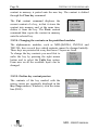
3.7. Selecting Communication Port
In the chapter 4.4 Keyboard
information we will discuss
how to get the information
about the keyboard and
integrated firmware through
the primary interface (it is set
to AT/PS2 at start-up and
current primary interface is displayed in bottom right-hand corner of the
main window – see Figure 16). In case, if you have connected MID
keyboard only to RS232 port then you may obtain the data through this
port as well just by selecting the port with Options->Communication
Port. Be aware, that also the other communication with the keyboard
(e.g. autodetect, download and upload) will be performed through this
port. Only the master modules version 03.00.xx support these additional
functions so it may happen, that some functions will not work.
3.8. Setting the matrix modules
The matrix modules are set in the following way: each key is assigned a
content that is sent when the key is pressed. These may be any of the sort
of standard keyboard keys' contents, character strings, key combinations
and special function keys of the programmable keyboard.
3.8.1. Writing default key configurations
Setting up the keyboard can be simplified with using the default key
attributes. With the menu option Options->Key defaults (Alt, O, D) you
can define common key attributes, which will be offered when a new,
blank key will be opened.
Common key attributes can be:
• Key click and Autorepeat function,
• RS232 output,
• Key size, etc.
MID - USER'S MANUAL
Page 22
SETTING UP THE KEYBOARD
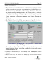
3.8.2. Key configuration input
To change the key settings you need to click on the selected key. The
following dialogue is opened:
Figure 21: Setting of the A1 key content
3.8.2.1. Special function keys
Special function keys are intended for controlling the keyboard.
These are the following:
- Shift to layer 1 (or 2, 3, 4): temporarily switch to layer 1 (or 2, 3, 4),
Shift layer keys can be due to the rollover problem only single sized
keys (refer to 4.5 Rollover).
- Step layer up/down: switch between layers up or down respectively,
- Lock to layer 1 (or 2, 3, 4): go to layer 1 (or 2, 3, 4),
- Click switch:
enable/disable beeping.
The keys type can be selected in Key type control element.
MID - USER'S MANUAL
SETTING UP THE KEYBOARD
Page 23
3.8.2.2. Content keys
•Key can have up to 4 different layer contents and every layer content
can be a sequence of characters, any combination of standard keys, etc.
The function keys of standard keyboards (e.g. Backspace, Enter etc.)
are literally recorded and displayed in the content line in a different
colour than normal keys with alphanumeric characters, just so a mixup with character strings cannot occur. For example, a string of entered
"Enter" characters is completely different from simply pressing the
Enter key.
•The Label fields are intended for entering names of specific key layers.
These labels can be later printed with the Print labels function.
Figure 22: Key properties
•On any layer, a key can be assigned a property of producing a sound
signal whenever pressed (soft click); a tick next to the Click control
element designates this.
•Content's auto-repeating is set through the Autorepeat control
element.
•Shape of the keys can also be set. Simply go to the control element
MID - USER'S MANUAL
Page 24
SETTING UP THE KEYBOARD
Shape and mark the chosen shape. Setting the keycap as a Blank
keycap disables the key.
•Interface and content type determines which interface should the
contents of the key be sent to (AT/PS2 or RS232) and how the contents
are entered (as scan codes or as ASCII). In the picture below you can
see the available options:
−
AT/PS2: Scan codes – contents are entered as normal scan
codes and are captured automatically by pressing the desired key.
You can enter any key combination, e.g. A, F11, CTRL-A, …
Since all scan codes are captured (also TAB) there is one reserved
key, used for exiting the scan line and is displayed in the status
bar. This key is by default Right-CTRL key and can be altered in
the Edit options.
(This mode is the default entry mode and is used normally).
Example:
In the scan line you can also enter a delay between two characters
or force a keyboard to beep. The special codes for so called
intercharacter beep and delay can be entered by the special keys,
which need to be assigned in the Edit Options menu (refer to 3.6
Edit options).
There are two different delay periods that can be entered: 100 ms
and 1s. You can enter of course a sequence of several delay codes
to get the appropriate delay (5 times 1s makes delay of 5s).
Whenever you start entering the codes you can see in the status
line which keys are assigned as special delay and beep keys
(Figure 22: Insert = Delay 100ms, Home = Delay 1s, PgUp =
Beep). If you want to use the original key value (e.g. key Insert =
Ins not Delay 100 ms) you need to reassign that key in the Edit
Options menu. By default there is no key assigned as special
Intercharacter beep and delay keys.
MID - USER'S MANUAL
SETTING UP THE KEYBOARD
Page 25
Example:
(the keyboard will send ABC, wait
1s and yet after that send DEF and beep at the very end).
−
AT/PS2: ASCII entry – contents are entered as chars and ASCII
codes. You can enter any character simply by pressing the key
(e.g. A,B,C,… ) or by entering the ASCII code. These codes should
be entered as decimal or hexadecimal numbers in-between pipe
characters (‘|’) 1.
Example:
−
AT/PS2: Code sequence – contents are entered as codes,
which should be sent from the keyboard to the system1. (Use this
option only if you are very familiar with the system architecture
and communication protocols!)
Example:
−
RS232: ASCII entry – contents are entered as ASCII signs and
codes. You can enter any character simply by pressing the key
(e.g. A,B,C, … ) or by entering the ASCII code. The codes should
be entered in-between pipes (‘|’) and can be entered as decimal or
hexadecimal numbers. The key contents are sent to the system
through the RS232 port1.
Example:
(If this field is disabled, change the Content edit mode to
Extended; refer to 3.6 Edit options).
1
NOTE: Code 0 is not allowed to be a part of the key content and
will be removed automatically.
Repeat the described procedure for each key of the keyboard. Thus, a
configuration catering for our every need can be created.
3.8.2.3. Copying/deleting keys
When several keys should hold the same content, the functions
Clear/Cut/Copy/Paste-content are used. Go to the key that needs
copying. Press the right mouse button and a window will pop up; choose
the Copy content command. The content of the key is now stored in
memory. Go to a new key and choose the Paste content command. The
MID - USER'S MANUAL
Page 26
SETTING UP THE KEYBOARD
content in memory is pasted onto the new key. The content is deleted
through the Clear key command.
The Cut content command displaces the
current content of a key, in that it stores the
content into memory and, at the same time,
deletes it from the key. The Paste content
command then copies the content in memory
onto the selected key.
3.8.2.4. Changing the contents on the predefined modules
The alphanumeric modules, such as MID-QM128A, PM128A and
TM128A, have several keys which contents cannot be changed initially.
These keys are protected in a way that lower 2 layers are fixed.
To change the key contents you need first to
unfix the key by pressing the right mouse
button and to select the Unfix key option.
From now on all the available layers can be
changed.
3.8.2.5. On-line key content preview
The contents of the key marked with the
mouse cursor are constantly displayed in the
Key Prop window (Windows), or in the status
line (DOS).
MID - USER'S MANUAL
SETTING UP THE KEYBOARD
Page 27
3.9. Setting up additional modules
3.9.1. Magnetic card reader
Up to three tracks on magnetic cards can be read with the MCR module.
The magnetic reader's track is active when the corresponding field in the
Enabled tracks control field is ticked. Entering data in the Header and
Terminator fields is only possible when the track is active. Field
contents are identical to the contents of the keys (refer to 3.8.2.2 Content
keys).
Figure 23: MCR properties
The Interface, Head/Term type field determines the MCR interface
(AT/PS2 or RS232) and how the contents of the Headers and
Terminators are entered (as scan codes, code sequence or ASCII).
The content of the magnetic card can be sent to the system either as ALTASCII codes or as scan codes in selected standard keyboard layout
(AT/PS2 mode only). This option can be selected in the Keyboard
settings window (refer to 3.5 Keyboard settings).
MID - USER'S MANUAL
Page 28
SETTING UP THE KEYBOARD
3.9.2. Matrix modules with integrated keylock
Matrix modules with integrated keylock are
displayed as two separated modules, a
matrix and a keylock module (in this case
key module 96 + keylock).
To change the keylock properties select the keylock module and the
following window appears:
Figure 24: Keylock properties with default values
When the position of the keylock is changed, the programmed content is
sent to the system. As you can see on the Figure 24 you can set a
different content in each keylock position.
The keylock contents can be entered in the same way as key contents –
they can be sent through AT/PS2 or through RS232 interface (for more
information about setting different interfaces and content types, refer to
3.8.2.2 Content keys).
MID - USER'S MANUAL
SETTING UP THE KEYBOARD
Page 29
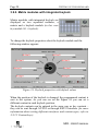
3.9.3. Matrix modules with integrated LCD
Matrix modules with integrated LCD are
displayed as two separated modules, a matrix
and LCD module (in this case key module 96 +
LCD 2x20 with backlight).
LCD functions (display string, clear display, go
to xy) can be tested in the LCD presentation
window, which is displayed when the LCD
module button is pressed.
1
2
3
8
9
10
11
12
5
6
7
Figure 25: LCD presentation window
4
The following functions can be tested:
• Display string: set the string that shall be displayed (1) and press
Display button (3). Nonprintable characters can be entered as
ASCII codes between brackets "|" - in this example ASCII 0 (=
defined as euro sign – see above).
Every entered char (in the box 1) can be displayed on-line on the
MID - USER'S MANUAL
Page 30
SETTING UP THE KEYBOARD
display if you check the Display every pressed key box (2);
• Goto x,y: set the column number (0..39, top) and the row
number (0..3, below), then press Go button (8);
• Displayed text can be shifted by entering the number of chars
and pressing the Go button (12) (negative numbers shift display to
the left);
• LCD's backlight can be turned ON and OFF in the section 11,
• The LCD display mode can be set in sections 5 and 6, and reset
to the default values with the Default button (9);
• Up to 8 different user defined characters can be set on the
ASCII positions 0 to 7. Define the character mask (5x8), the char
number and press the Go button (7). In this example the Euro
sign is designed as the ASCII character 0.
• The Interface field(9) shows the primary interface for the
communication. You may change it as displayed in chapter 3.7.
A combination of integrated LCD and keylock module is also possible.
The MID keyboard is displayed in this case as a composition of three
modules.
* DOS version of the download program may not support some LCD test
functions.
3.9.4. Matrix module with integrated smart card reader
The existing module MID-KM032S integrates
besides 16 programmable keys a smart card
reader and a 2x16 character LCD.
MID - USER'S MANUAL
KEYBOARD FEATURES
Page 31
Some basic test functions are integrated in the download program power ON/OFF, sending a command to the LCD and reading the content
of the memory cards.
1
2
3
4
5
Figure 26: Smart card reader window
How to read the content of the memory card (based on the Siemens SLE
4432/4442 IC):
1. Insert the card
2. Press the Power ON Mem button (2) (in the Card Properties
section (1) you can see the type of the inserted card)
3. Press the Read Mem button (3) (the whole content of the card is
displayed in the Response block (5))
4. Press the Power OFF button (4) (now you may take out the card)
* DOS version of the download program may not support some ICCR
test functions.
MID - USER'S MANUAL
Page 32
KEYBOARD FEATURES
3.9.5. Matrix module with integrated identification button
reader (iButton)
The MID iButton Reader is a built-in option for
MID KM (Key Matrix) modules. It consists of
the iButton socket/holder, which is mounted on
the top right-hand corner of the housing and
associated electronic circuitry. Since the socket
is magnetized it holds firmly the inserted
iButton.
Every iButton holds its unique identification number, which is sent
toward the system when the button is inserted in the socket. Three
programmable sequences, which are sent along with this ID number,
define the output interface and help the system application to
differentiate between keyboard and iButton data.
Below you can see the sequence order of the iButton actions:
Action
What is sent
toward the system
IButton is inserted
Insertion
Header
ID
number
Insertion
Terminator
IButton is
removed
Removal
Header
All programmable sequences can be programmed same as any
programmable key (see 3.8.2.2). The field Interface defines the
communication interface for the sent data (could be AT/PS2 or RS232).
The settings flags, which can be defined in the bottom-left hand corner of
the window, shall be used only in some special occasions, when some
part of the data (e.g. Removal Header) should not be sent.
!
WARNING: Socket of the reader is a permanent
magnet. Do not place MAGNETIC CARDS (as well as
anything else sensitive to the magnetic field) in close
proximity of the reader in order to prevent damage!
MID - USER'S MANUAL
KEYBOARD FEATURES
Page 33
Figure 27: iButton Properties dialogue
F
NOTE: Set and Get iButton Mode functions shall be
used for special use only!
3.9.6. Bar Code Reader (BCR)
Both two different types of MID Bar Code
Readers (MID BCR Slot reader – left and MID
BCR Input - right) are supported in MIDWIN.
MID BCR is a Bar Code Slot Reader designed as a slave module for the
MID keyboard. The module, which is integrated in the same housing as
MID MCR, provides fully programmable header and terminator (that are
appended to the bar code data), as well as two other programmable event
descriptions for identifying successful/failed readings.
MID - USER'S MANUAL
Page 34
KEYBOARD FEATURES
MID BCR INPUT is a RS232 pass-through port, optionally integrated
on the master module. Since all the port settings are programmable a
variety of readers with decoded RS232 serial output could be connected.
Incoming data are modified and rerouted to the selected AT/PS2 or
RS232 interface. Those data stream modifications include several
programmable features, such as appending of header (prefix) and a
terminator (suffix) sequence.
Figure 28: Defining headers and terminators
Four different programmable sequences enables the BCR unit to fulfil
many system software requirements, these are:
• Success code is generated when the bar code has been successfully
read. The action is executed before any data is sent.
• Fail code: this sequence indicates that the code has not been read
successfully.
• Start code and End code are sent right before and after usefully
bar code data. The interface type of these codes defines the port
(AT/PS2 or RS232), where the data shall be sent.
MID - USER'S MANUAL
KEYBOARD FEATURES
Page 35
The sequence order of the sent data:
Bar code
successfully read
Bar code
unsuccessfully
read
F
Success code Start code
Bar code data End Code
Fail code
NOTE: Beeping as a part of the sequence could be
entered only if the interface type is selected to
AT/PS2 Scan codes. Since the interface could be
different for Success/Fail code and for Start/End
code you can set beeping as a success and fail
code even if the primary interface type (Start/End
code) is set to RS232.
The BCR Properties page consists of two additional sub-pages, where
you can define the parameters of the connected Bar Code reader. As a
help tool there are few types of the BCRs already predefined in the
Predefined Settings scroll down menu.
All set settings are saved in the keyboard layout file along with all
properties of all keys.
MID - USER'S MANUAL
Page 36
KEYBOARD FEATURES
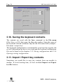
3.10. Saving the keyboard contents
The contents are saved with the Save command in the File menu
(File->Save, or F2), that opens the Save As window. Enter the name of
the keyboard with the extension .lay into the File name field (example File name: example.lay).
The keyboard configuration is automatically saved into the separate file
as well. Information on how to save and open the keyboard configuration
file can be found in the chapters 2.3.5 Saving configurations and 2.3.6
Opening existing configurations.
3.11. Import / Export key contents
Sometimes you would like to copy key contents from one module to
another. To avoid wasting time, we have included Import and Export
text file features.
MID - USER'S MANUAL
KEYBOARD FEATURES
Page 37
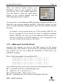
These two features highly increase your
flexibility. You can save contents of keys
into the text files, each module separately.
You just need to press the right mouse
button on the selected module and the
following popup menu is opened.
You may have several different MID keyboard configurations and all of
them have one or more identical modules. With these options you can
create as many different configurations while the basic module remains
the same.
An example: your program needs one 128 key module (KM128), but
for one customer it is not enough, he wants an additional numpad
module (KM032), the other one wants additional MCR module etc.
Instead of building the KM128 module for each configuration you
can copy it from one keyboard to the others.
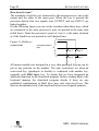
3.11.1. MID export text file format
Exported key contents are saved in the MID export text file format
(filename.mtx). This format is used not only by exporting and importing
key contents but also by reading the definition of fixed keys (e.g.
QWERTY module).
Here is listed an example of exported text file:
A1/S/CT/A++++/C++++/F++--/~1~{F1}~~~!~1~~~
A2/S/CT/A++++/C++++/F++--/~2~{F2}~~~@~2~~~
A3/S/CT/A++++/C++++/F++--/~3~{F3}~~~#~3~~~
A4/S/CT/A++++/C++++/F++--/~4~{F4}~~~$~4~~~
A5/S/CT/A++++/C++++/F++--/~5~{F5}~~~%~5~~~
Every following line consists of key definition (describing first line):
A1 : co-ordinate of the key (left-hand upper key)
S : single key (C = Custom key etc.)
CT : content key (S2 = Shift to layer 2 etc.)
A++++ : autorepeat: key has in all layers autorepeat function
MID - USER'S MANUAL
Page 38
KEYBOARD FEATURES
C++++ : key click function: key has in all layers click function
F++-- : fixed layers: layer 1 and 2 are fixed, 3 and 4 are programmable
~1~{F1}~~~ : 4 contents, separated by ~
content 1 is letter 1,
content 2 is key F1,
contents 3 and 4 are blank,
*** all contents are described in the US English layout and are
translated when importing;
~!~1~~~ : 4 labels, separated by ~
label 1 is letter !,
label 2 is letter 1,
labels 3 and 4 are blank.
3.12. Program version
The Help->About from the Main Menu provides full information on the
software release:
• MIDWIN version code (e.g. Ver. 3.0.7)
• Release date (e.g. September 04, 2000)
• Name, version code and release date of the DLL with Printing key
labels utility (e.g. Cover32.DLL ver 3.0.0, 24.07.2000)
• Name, version code and release date of the DLL with low-level
keyboard communication (e.g. WKMIDAPI.DLL ver 3.0.1,
28.07.2000)
MID - USER'S MANUAL
KEYBOARD FEATURES
Page 39
4. Keyboard features
4.1. Programming the keyboard
The Download function saves settings of all
modules and all keys into the MID’s internal
non-volatile memory.
With the additional Verify function you can
check if the data have been successfully
stored.
4.2. Testing the keyboard
The accuracy of the programming can be
tested in the test windows. The keyboard can
be tested either in the AT/PS2 or in RS232
mode.
To test the AT/PS2 keyboard output choose the menu command
Tools->Text window (Alt, T, T) and the normal text input window is
displayed.
First verify the layer switching keys. When such key is pressed (its
content being a switch to a certain layer), an appropriate LED diode
should light up on the keyboard. The active LED diode represents an
active layer for the whole keyboard (all the matrix modules). The display
in the test window must fit the content of the currently active layer.
4.2.1. Testing the RS232 keyboard
With the menu command Tools->TTY terminal (Alt, T, Y) you can test
the codes coming from the keyboard through the RS232 interface.
First the program asks for the connected serial port and the baud rate,
which can be changed later also.
MID - USER'S MANUAL
Page 40
KEYBOARD FEATURES
Figure 29: TTY terminal
The data coming from the keyboard to the system can be displayed as
ASCII or hexadecimal codes (check Show Hex Codes) in the field.
4.3. Uploading the keyboard
It may happen that you would like to check
what is programmed in the MID. The
Upload function reads the content of the
connected MID and displays it on the
desktop.
4.4. Keyboard information
Sometimes you need the compressed information about the arranged
keyboard. You would like to know, how much of the free keyboard
memory is still available, how many matrix modules can be added, how
many extra sized keycaps do you need, etc. This all can be displayed in
the Keyboard info dialogue window if you select Keyboard->Info (Alt,
K, I) option.
MID - USER'S MANUAL
KEYBOARD FEATURES
Page 41
Figure 30:Keyboard info window
The displayed keyboard parameters are:
Free:
shows how many memory bytes, keys and matrix modules are
free to be used,
Statistics: shows key content usage,
Keycaps: shows the number of single keycaps, double vertical, etc.,
Module VER & IDs: the list of IDs and firmware versions of the master
module and all connected modules.
4.5. Rollover
4.5.1. What is rollover
Sometimes, when three or more keys are pressed at the same time, the
microprocessor in the keyboard detects that also an extra fourth key was
pressed. This fourth key is called the Ghost key, and the situation when
this happened is called the rollover. Since a keyboard cannot know
which specific key combination was used (might be any 3 of these 4
keys, or all 4) it reacts as if an illegal condition has occurred. The
Modular keyboard warns the user with a beep that something illegal
was pressed, and sends no code to the system.
MID - USER'S MANUAL
Page 42
KEYBOARD FEATURES
How does it occur?
The terminals of each key are connected to the microprocessor, one to the
output and the other to the input port. When the key is pressed the
processor detects that two signals (one OUTPUT and one INPUT) are
linked together.
On the following figure you can see the situation when three keys, which
are connected to the same processor‘s port, are pressed at the same time
(solid lines). From the processor‘s point of view it is the same situation
as if the fourth key was pressed as well (dashed line).
Figure 31: Rollover connections
microprocessor’s
port
key 1
key 3
key 2
key 4
All matrix modules are designed in a way, that quadruple keycap can be
put at any position on the module. The only restrictions are when an
extra-sized key (quadruple or double) is combined with another key,
normally with Shift layer key. To obtain this we have integrated an
additional function in the download program. Before sending data to the
keyboard memory the download program checks if there are any
prohibited combinations of Shift layer keys and extra-sized keys. The
data are downloaded only if the keyboard layout was designed properly.
MID - USER'S MANUAL
KEYBOARD FEATURES
Page 43
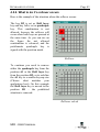
4.5.2. What to do if a rollover occurs
Here is the example of the situation where the rollover occurs.
The key D2 is set as Shift layer
key and key A1 is set as quadruple
key. This combination is not
allowed, because the rollover will
occur when both keys are pressed at
the same time. As you can see on
the figure the not allowed
combination is coloured, and the
problematic quadruple key is
signed with the question mark.
Rollover
To continue you need to remove
either the quadruple key from the
position A1 or the Shift layer key
from the position D2, or to redefine
the A1 key to a smaller keycap size
(Choose what matches your
application best). On this example
the Shift layer key is moved to the
position H1 – the prohibited
situation is removed.
Rollover solved
MID - USER'S MANUAL
Page 44
KEYBOARD FEATURES
5. Other utilities
5.1. Printing key labels
Integrated in MIDWIN, is the ability to print keycap labels. The program
allows you to print labels in different colours, font types and sizes.
There are 4 label fields in the key definition window (refer to 3.8.2 Key
configuration input) where you can put the text that should be written on
the keycaps. Only the non-blank fields are printed on the default-selected
printer.
The command File->Print labels (ALT, F, P) opens the window, where
the keycap labels can be edited and printed.
On the figure below you can see an example of configured keyboard, the
description of the significant parts follows:
1
2
3
4
5
6
Figure 32: Printing labels
MID - USER'S MANUAL
KEYBOARD FEATURES
Page 45
1. With these two buttons you can save the entered changes to the key
labels or exit this window and return back to the main window. The
label properties are saved in a file with the extension .cov while the
changes of the label texts are saved in the keyboard layout file and are
therefore visible in the key definition window.
2. Key labels are printed separately, each size on a different page. With
these 5 buttons you can print labels on Single/Double
horizontal/Double vertical or Quadruple keycaps. If you want to
print all pages at once you need to press the button All.
3. The Draft button starts printing of the complete keyboard layout on
single page. Since all single, double and quadruple keycaps are visible
on the same sheet, this feature is very useful for layout design and
verification. The drawback of such printout is disproportional size of
double and quadruple keycaps. Therefore it shall not be used for final
labels assembling.
4. The option Print preview enables you to see the printed layout before
printing.
5. Only labels on one module can be seen at once. You can change the
visible module with keys in the upper row.
6. Each key can have up to 4 different labels printed on the inserted
paper. You can set different font type, text and background colour,
font style (bold, italic and underline), alignment and font size for each
label separately. Font size can be set automatically to maximum
(check the Autosize field) or manually. Font size cannot be bigger
than the one that fits onto the key label. For the background colour
also a custom colour could be selected.
To change the key label properties first click on the selected field (if the
keycap size is bigger than single keycap you should click the upper lefthanded corner) and then change the text, colour and other text
properties.
i
IMPORTANT: use the right mouse button to select
multiple keys!
MID - USER'S MANUAL
Page 46
KEYBOARD FEATURES
5.2. MID API
MID Application Programming Interface (MID API) is a set of functions
that your application can call to perform specific commands on TIPRO
MID modules. MID API communicates to MID via AT/PS2 keyboard or
serial interface. It supports the following platforms: Windows 95/98,
Windows NT and Windows 2000.
The MID family consists of many different modules, which you can
combine into sophisticated input device. Modules differ in size and
functionality. Some of them don't need any special API functions in order
to operate (matrixes), but the others can't live without them (LCD's, smart
card readers, etc.). We created MID API in order to allow programmers to
develop applications for TIPRO modular keyboards.
The libraries, H files, examples for various Windows programming tools
and a comprehensive documentation of the MID API are already included
in the standard MIDWIN installation. No additional installation is
required.
MID - USER'S MANUAL
TECHNICAL DATA
Page 47
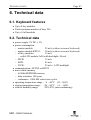
6. Technical data
6.1. Keyboard features
•Up to 8 key modules
•Total maximum number of keys 256
•Up to 14 all modules
6.2. Technical data
•power supply: 5V DC ± 5%
•power consumption
− master module:
25 mA (without external keyboard)
− master module RS232:
30 mA (without external keyboard)
− all key modules:
15 mA
- with LCD module 2x20 with backlight: 90 mA
− MCR:
15 mA
− BCR:
45 mA
− ICCR:
25 mA + LCD backlight
•communication: AT/PS2 or RS232
•non-volatile memory
− 64 Kbit EEPROM memory
− data retention: 100 years
− endurance: 1 000 000 write/erase cycles
•operating temperature range : 0 – 40°C (32 –104F)
•storing temperature range: -20 – 60°C (-4 – 140F)
•relative humidity range:
20%-85% (non-condensing)
MID - USER'S MANUAL
Page 48
TECHNICAL DATA
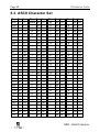
6.3. ASCII Character Set
Char
NUL
SOH
STX
ETX
EOT
ENQ
ACK
BEL
BS
HT
LF
VT
FF
CR
SOH
SI
DLE
DC1
DC2
DC3
DC4
NAK
SYN
ETB
CAN
EM
SUB
ESC
FS
GS
RS
US
Dec
0
1
2
3
4
5
6
7
8
9
10
11
12
13
14
15
16
17
18
19
20
21
22
23
24
25
26
27
28
29
30
31
Hex Char Dec
0 Space 32
01
!
33
02
"
34
03
#
35
04
$
36
05
%
37
06
&
38
07
'
39
08
(
40
09
)
41
0A
*
42
0B
+
43
0C
,
44
0D
45
0E
.
46
0F
/
47
10
0
48
11
1
49
12
2
50
13
3
51
14
4
52
15
5
53
16
6
54
17
7
55
18
8
56
19
9
57
1A
:
58
1B
;
59
1C
<
60
1D
=
61
1E
>
62
1F
?
63
Hex
20
21
22
23
24
25
26
27
28
29
2A
2B
2C
2D
2E
2F
30
31
32
33
34
35
36
37
38
39
3A
3B
3C
3D
3E
3F
Char Dec Hex Char Dec Hex
@
64 40
`
96 60
A
65 41
a
97 61
B
66 42
b
98 62
C
67 43
c
99 63
D
68 44
d 100 64
E
69 45
e 101 65
F
70 46
f
102 66
G
71 47
g 103 67
H
72 48
h 104 68
I
73 49
i
105 69
J
74 4A
j
106 6A
K
75 4B
k 107 6B
L
76 4C
l
108 6C
M
77 4D
m 109 6D
N
78 4E
n 110 6E
O
79 4F
o 111 6F
P
80 50
p 112 70
Q
81 51
q 113 71
R
82 52
r
114 72
S
83 53
s 115 73
T
84 54
t
116 74
U
85 55
u 117 75
V
86 56
v 118 76
W
87 57
w 119 77
X
88 58
x 120 78
Y
89 59
y 121 79
Z
90 5A
z 122 7A
[
91 5B
{
123 7B
\
92 5C
|
124 7C
]
93 5D
}
125 7D
^
94 5E
~ 126 7E
_
95 5F DEL 127 7F
MID - USER'S MANUAL
TECHNICAL DATA
Page 49
6.4. Specification of the serial
communication
Baud rate: Selectable to 9600, 4800, 2400, 1200, 600 or 300 Baud
Data bits: 8
Parity:
None
Stop bits: ONE
Protocol: Tipro defined protocol
The protocol guidelines can be obtained from the Tipro web site:
http://www.tipro.net/Support/Docs/MidMisc/RS232PRO.doc
6.5. Keyboard modules
6.5.1. Full travel keyboard modules
Full travel modules are
equipped with Cherry MX
mechanical keyswitches.
Thanks to "gold
crosspoint" contact
technology and 4 mm
travel these modules are
satisfying the most
demanding user's
requirements.
MID - USER'S MANUAL
Page 50
COPYRIGHTS/WARRANTY/TECHNICAL SUPPORT
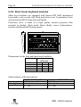
6.5.2. Short travel keyboard modules
Short travel modules are equipped with Omron B3F 4005 mechanical
keyswitches and covered with fixed protection cover. It guarantees front
side protection (IP65) from dust and liquids.
Protection cover is made of a high quality textured polyester film
resistant to alcohol, dilute acids, dilute alkalis, esters, hydrocarbons,
ketones and household cleaning agents.
Dimensions for the long and short travel modules:
Matrix size
4 x 8 (32)
ICCR
8 x 8 (64)
12 x 8 (96)
16 x 8 (128)
housing dimension
W/D/H [mm]
93
210
93
210
196
210
246
210
322
210
42,5
48
42,5
42,5
42,5
Main features of the keyswitches:
lifetime
actuating force
key travel
long travel - Cherry MX
> 50 million operations
(60 ± 20) cN
short travel - OMRON B3F
> 300 000 operations
(255 ± 65) cN
4 − 0, 4 mm
0,3+− 00,,12 mm
MID - USER'S MANUAL
COPYRIGHTS/WARRANTY/TECHNICAL SUPPORT
Page 51
6.5.3. Integrated iButton module
IButton properties:
•ROM (Read Only Memory) pre-programmed with unique 64-bit
registration number
•Operating/Storage Temperature Range: -40°C to +85°C
•Mechanical Shock:
500g’s (6 axis)
•Immersion in Saline: 24 hours
•Drop Test:
1.5m to concrete
•Crush Test
12kg for 30seconds
•Contact Durability:
1million insertion
6.6. MCR modules
•Connectors: 2 internal connectors for side
connection with other MID modules
•Weight: 250 g
•Power consumption: 15mATYP
•Package: module with magnetic card reader
•Reads tracks 1+2 or 2+3 or 1+2+3
•In conformance with: ISO 7811 standard
•Head operating life: up to 1 million card passes
with ISO 7810/7811 conformed cards
•Card thickness range: 0.18 mm to 0.84 mm
•Stripe media coercitivity range: both Lo-Co and
Hi-Co (more than 4200 Oe)
•Card feeding speed: (5 – 150) cm/s
MID - USER'S MANUAL
Page 52
COPYRIGHTS/WARRANTY/TECHNICAL SUPPORT
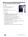
6.7. IC Card Reader modules (ICCR)
Consists of
•ICC Reader
•2x16 character alphanumeric LCD
•4x4 free programmable keys
•Weight: 520 g
•Power consumption: 20 mATYP + IC card
consumption
IC Card Reader
•In conformance with: ISO 7816 standard, PC/SC specification
•Supported asynchronous protocols: T = 0, T = 1
•Supported synchronous protocols: S = 10
•Asynchronous baud rate: 10752baud (4MHz /372)
•Synchronous bit rate: approximately 30kb/s
•Detecting and reporting ICC insertion and withdrawal
•IC contacts position: ISO 7816 compliant
•IC contacts type: landing
•IC contacts material: copper alloy with gold over nickel plating
•IC contacts pressure: 1.5 NMAX per contact
•Card insertion force: 10 NMAX
•Card withdrawal force: 3 NMIN
•Durability: more than 200000 cycles (insertion/withdrawal)
MID - USER'S MANUAL
COPYRIGHTS/WARRANTY/TECHNICAL SUPPORT
Page 53
6.8. Bar Code slot Reader (BCR)
•Connectors: 2 internal connectors for side
connection with other MID modules
•Weight: 250 g
•Power consumption: 45 mA
•Package: module with bar code slot reader
•Light Source: 660 nm red LED
•Light Sensor: photo diode
•Resolution: 0.15 mm (6 mils)
•Height of Scan Line: 10.5 mm
•Card Swiping Speed: 100 – 1000 mm/sec
(3.9 – 39.0 inch/sec)
•Card Thickness: up to 1.8 mm
•Ambient Light: up to 3000 lux
•Supported Bar Codes: all types of UPC/EAN/JAN, Code 3 of 9, Code
3 of 9 full ASCII, Code 128, Code 93, Interleaved 2 of 5, Industrial 2
of 5, Matrix 2 of 5, Codabar, MSI/Plessey, Code 11
6.9. Accessories
Accessory is a set of equipment necessary to assemble the keyboard. It
consists of:
•two side covers (left and right)
•one joiner
•one cable for communication with the computer
Accessory for master with both RS232 and AT, PS/2 interface encloses a
cable with split end on the computer side - for keyboard and RS232
connection.
6.10. Ordering Codes
Tables with ordering codes for all key modules, MCRs, BCRs,
accessories and cables can be obtained on the Tipro home page:
http://www.tipro.net/Support/Docs/MidMisc/ordcodes.htm
MID - USER'S MANUAL
Page 54
COPYRIGHTS/WARRANTY/TECHNICAL SUPPORT
7. Copyrights and technical
support
Copyrights
MIDDOS Copyright by Tipro keyboards d.o.o.
MIDWIN Copyright by Tipro keyboards d.o.o.
MID™ and Modular input device™
are trademarks of Tipro keyboards d.o.o.,
All rights reserved
iButton® is registered trademark of Dallas Semiconductor.
IBM® is registered trademark of International Business Machines
Corporation.
Microsoft® and Windows™ are either registered trademarks or
trademarks of Microsoft corporation.
Software distribution
MIDDOS and MIDWIN are distributed with MID Master module. It is
free software and may be used by any number of systems.
Modification of the programs or their resources is strictly forbidden. Any
modification of any component of the MIDDOS or the MIDWIN are a
breach of intellectual property laws in most countries and will be pursued
vigorously to the full extent of the law.
No liability for consequential damages
Tipro keyboards and its suppliers shall be in event liable for any damage
(including without limitation, special, incidental, consequential, or
indirect damages for personal injury, loss of business profits, loss of
business information, or any other pecuniary loss) arising out of the use
of or inability to use this product.
MID - USER'S MANUAL
COPYRIGHTS/WARRANTY/TECHNICAL SUPPORT
Page 55
Technical support
Your first port of call for technical support for MIDWIN is this manual
and the list of frequently asked question on the Internet. The address of
the Tipro Technical support web site is:
http://www.tipro.net/tehnical.htm
If these sources do not give satisfactory answers you may contact our
technical support by Email or Fax. We endeavour to answer questions
within 48 hours (except on holidays, weekends and working free days).
Contact Tipro keyboards
Via
Internet
Fax
Mail
At
[email protected]
+386 1/78 88 299
Tipro keyboards
Ljubljanska cesta 64
SI-1290 Grosuplje
Slovenia
Updating software
Both the download programs, MIDDOS and MIDWIN, will be regularly
updated on our www home page. If you need to install new version of the
download program you have to get either the MIDDOS or the MIDWIN
setup program from the following Internet sites and run it as written in
chapter 3.1 Program installation.
HTTP:
www.tipro.net (follow Support)
Or directly: www.tipro.net/technic.htm#MIDWIN
MID - USER'S MANUAL
http://www.tipro.net
™