1
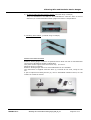
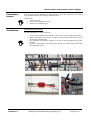
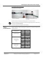
VIBRATING WIRE AND
RESISTIVE STRAINGAUGES
User Manual
Vibrating Wire and Resistive Strain-Gauges
INDEX
Introduction
Pag. 4
Description
Pag. 4
Preliminary checks
Pag. 6
Installation
Pag. 6
Taking measurements
Pag. 8
Data management
Pag. 9
Troubleshooting
Pag. 10
Maintenance
Pag. 10
Appendix 1
Pag. 11
Information contained herein are property of SISGEO S.r.l. This document is subject to change without notification and is subject to be returned upon request. No part of this User’s Manual may
be reproduced in any form without SISGEO’s S.r.l. written permission.
SISGEO S.r.l.
Vibrating wire and resistive strain gauges_EN_00_12
Page 2 of 11
Vibrating Wire and Resistive Strain-Gauges
Notes on the use of
product
For a safe and efficient use of the instrument, please read carefully the following instructions
before starting any operation.
Any use of the instrument other then the one described in this manual shall be considered at user’s full
responsibility.
The same applies for any unauthorized modifications.
In addition to the hereby listed standards, the user must comply with the provisions of the current
legislation on the matter of personal safety and health of persons in the workplace.
SISGEO is not responsible for any trouble, breakdowns, accidents etc.. due to the lack of knowledge and/or
confidence (or non-compliance with) with the requirements contained in this manual.
Check that the instrument has not been damaged during the transport.
Verify that the package includes all items as well as any requested optional accessories; if anything is
missing, please promptly contact the manufacturer.
The user must strictly follow all the operations described in this manual.
Maintenance or repair of the instrument is allowed only to authorized operators.
These operators must be physically and intellectually suitable.
For information about instrument or order spare parts request, please always specify data written on the
identification label.
When replacing parts, always use ORIGINAL SPARE PARTS.
The manufacturer reserves the right to make changes without prior notice for any technical or commercial
requests.
We’ll try anyway to keep the manuals updated in order to reflect product’s revisions/updates.
Symbols
This symbol will be used used to catch reader’s attention on the manual:
Pay special attention to the following instruction.
Identification
SISGEO S.r.l.
Instruments can be identified
•
From a production lot number (written on the Compliance Certificate)
•
From a serial number (s/n) engraved indelibly on the instrument
•
From a label on the instrument
•
From a label on the cable
Vibrating wire and resistive strain gauges_EN_00_12
Page 3 of 11
Vibrating Wire and Resistive Strain-Gauges
Introduction
Strain-gauges measures strain in steel, concrete or reinforced concrete structures.
Once integral with the constructions to be monitored, they change the electric signal
according to the strains.
Description
Strain-gauges can be vibrating wire (VW) or resistive.
VIBRATING WIRE STRAIN-GAUGES
They consist in a hollow cylindrical body with an internal steel wire stretched
between the two ends.
Outside, a resin cover protects the coil.
An internal thermistor allows temperature measurement.
VW strain-gauges can be:
1) Embedment VW Strain-Gauges (nominal range ±1500µε)
Embedment VW
strain-gauges
3D strain-gauge
assembly
2) Arc-Weldable VW Strain-Gauges (nominal range ±1500µε)
Fully assembled
arc- weldable vw
strain-gauges
Mounting
blocks
Straingauge
Mounting jig
3) Embedment VW Strain-Gauges for Shotcrete (nominal range ±5000µε)
SISGEO S.r.l.
Vibrating wire and resistive strain gauges_EN_00_12
Pagina 4 di 11
Vibrating Wire and Resistive Strain-Gauges
4) No Stress VW Embedment Strain-Gauge (nominal range ±1500µε)
They are assembled in an ABS box and embedded in concrete. Since it will not
deformed, it is used with other strain-gauges for thermic compensation.
5) Vibrating Wire Rebars (nominal range ±1500µε)
RESISTIVE STRAIN-GAUGES
Resistive strain-gauges consist in a squared-section steel rod with 4 extensometers
connected in Wheatstone bridge configuration.
They have electric signal 4-20 mA current loop, V/V and V.
Nominal range is ±1500µε.
Resistive strain-gauges can be for CLS embedment or arc-weldable.
The instrument is supplied with two discs (1) screwed at the ends, ready for the
use.
A pair of optional mounting blocks (2), can be assembled instead of discs, for the
welding on metal structures.
1
2
SISGEO S.r.l.
Vibrating wire and resistive strain gauges_EN_00_12
Pagina 5 di 11
Vibrating Wire and Resistive Strain-Gauges
Preliminary
checks
Before starting the installation we recommend to check the instrument connecting
to a portable readout (see “Taking Measurements”).
Useful
•
•
•
Installation
tools:
Allen key SW3
iron tie (for embedment type)
welder (for weldable type)
Embedment Strain-Gauges
For the installation proceed as follows:
•
•
•
•
Tie the strain-gauges on the rebar so they won’t move during the grouting;
With the vibrating wire model, tie lightly over the black sheath in order to
protect the cylinder body.
Pay attention through the grouting in order to avoid damaging the straingauges.
For the 3D assembly, block the strain gauges on the mounting block with
the supplied screws.
Installation examples:
SISGEO S.r.l.
Vibrating wire and resistive strain gauges_EN_00_12
Pagina 6 di 11
Vibrating Wire and Resistive Strain-Gauges
Arc-weldable strain-gauges
To install please proceed as follows:
Insert the mounting jig in the
mounting blocks
Clean the surface and weld
the mounting blocks
Proceed with the remaining
screws until the mounting
jig is blocked
Tighten the first screw
Once the monting blocks are
cold, remove the mounting
jig
Insert the strain-gauge and
block it with the screws
Connect the strain-gauge to the readout and check that the value is approximately
2500µε ±10%.
The strain-gauge can be adjusted unscrewing the screws on the open mounting
block; once adjusted, tighten the screws.
The strain-gauge has a nominal range of 1000÷4000µε.
Do not exceed this values to avoid damaging it irreparably.
Installation examples:
SISGEO S.r.l.
Vibrating wire and resistive strain gauges_EN_00_12
Pagina 7 di 11
Vibrating Wire and Resistive Strain-Gauges
Arc-weldable resistive strain-gauges
To install proceed as follows:
Remove terminal discs
Assemble the mounting blocks on the
strain-gauge.
Clean the surface and weld the mounting blocks in the chosen position.
During the welding we recommend to protect the strain-gauge and the cable with a
wet rag to avoid heath damaging.
If necessary apply anti-rust paint on the weldings.
Taking
measurements
Manual readings are taken connecting the conductors to a readout according to the
following scheme:
4-20 mA current loop
strain-gauges
VW strain-gauges
strain-gauges
Red
+ Loop
Black
- Loop
Red
VW
Black
VW
White
Thermistor
Green
Thermistor
Red
+ Vcc
Black
GND
Blue
+ Sensing
Green
- Sensing
Yellow
+ Out
White
- Out
Red
+ Vcc
Black
GND
Yellow
+ Out
White
- Out
ratiometric signal
(V/V)
Strain-gauges
Voltage signal
(V)
SISGEO S.r.l.
Vibrating wire and resistive strain gauges_EN_00_12
Pagina 8 di 11
Vibrating Wire and Resistive Strain-Gauges
For automatic measures, connect the instrument to a datalogger.
To obtain reliable measures, with 4-20mA instruments, we recommend a warm up
time not less than 10 seconds.
Data
management
VIBRATING WIRE STRAIN-GAUGES
SISGEO readout provide the deformation measure directly in µε.
Conversion is based on the following equation:
µε = ( f 2 × 10 −3 )× G
where:
• f: is the wire vibration sequence in Hertz
G: is the gauge factor that can be obtained from the “Compliance Certificate”.
Note: (f2 x 10-3) is also named “Digit”
G nominal values for the main models are:
•
0VK4100VS00 = 0.391
•
0VK4000VS00 = 4.043
•
0VK4200VC00 = 3.814
The exercise readings refer to the initial zero reading.
∆µε = Li - L0
L0 = zero reading (µε)
Li = exercise reading (µε)
Zero reading shall be taken carefully once the installation is performed and the
instrument is in operating conditions.
Temperature reading
SISGEO readout display the temperature directly in °C.
If the thermistor resistance value is taken, please use the conversion formula in
Appendix 1.
RESISTIVE STRAIN-GAUGES
With the resistive strain-gauges, the following formula allows to convert the electric
measurements into engineering values:
Ling = Lele/S [µε]
Ling = engineering reading
Lele = electric reading
S = sensitivity factor (obtained from Compliance Certificate)
SISGEO S.r.l.
Vibrating wire and resistive strain gauges_EN_00_12
Pagina 9 di 11
Vibrating Wire and Resistive Strain-Gauges
Troubleshooting
Vibrating wire strain-gauges
Problem
Possible cause
Solution
Instrument out of range
None
Cable shield not connected
Connect the shield
Electromagnetic fields generated by
Measure not
engines, generators, antennas,
stable
welders or high voltage lines nearby
Insulation loss
Wire not
detected
Identify and remove the cause.
Shield the signal cable.
None
Grounding not well done
Provide efficient grounding
Cable cut or damaged.
Measure the resistance between the
red and black conductors.
Acceptable values : 160Ω ± 10%.
Consider cable length.
Uncorrect wiring
Repair the cable: cable splicing kit is
available at SISGEO.
Make proper wiring
Resistive strain-gauges
Problem
Unstable
measure
0mA
measure
Overrange
measure
Maintenance
Possible cause
Solution
Uncorrect wiring
Make proper wiring
Cable cut or damaged
Repair the cable.
Cable splicing kit available at
SISGEO.
After-sales assistance for calibrations, maintenance and repairs, is performed by
SISGEO’s service department.
The authorization of shipment shall be activated by RMA “Return Manufacturer
Authorization". Fill in the RMA module clicking on:
http://www.sisgeo.com/en/assistance/repairs/
Send back the instrument/equipment with the complete accessories, using suitable
packaging, or, even better, the original ones.
The shipping costs shall be covered by the sender.
Please return to the following address with suitable delivery document:
SISGEO S.r.l.
Via F.Serpero, 4/F1
20060 MASATE (MI)
On the delivery document is mandatory to indicate the RMA code received.
Technical assistance e-mail: [email protected]
SISGEO S.r.l.
Vibrating wire and resistive strain gauges_EN_00_12
Pagina 10 di 11
Vibrating Wire and Resistive Strain-Gauges
Appendix 1
THERMISTOR TEMPERATURE CONVERSION
Resistance to temperature equation:
T=
1
− 273.2
3
A + B (LnR ) + C (LnR )
Where:
T= temperature in °C
LnR= natural Log of the thermistor resistance
A= 1.4051x10⁻³ (coefficents calculated over the -50 to +70°C span)
B= 2.369x10⁻⁴
C=1.019x10⁻⁷
SISGEO S.r.l.
Ohms
Temp
Ohms
Temp
Ohms
Temp
Ohms
Temp
16.60K
-10
5971
10
2417
30
1081
50
15.72K
-9
5692
11
2317
31
1040
51
14.90K
-8
5427
12
2221
32
1002
52
14.12K
-7
5177
13
2130
33
965.0
53
13.39K
-6
4939
14
2042
34
929.6
54
12.70K
-5
4714
15
1959
35
895.8
55
12.05K
-4
4500
16
1880
36
863.3
56
11.44K
-3
4297
17
1805
37
832.2
57
10.86K
-2
4105
18
1733
38
802.3
58
10.31K
-1
3922
19
1664
39
773.7
59
9796
0
3784
20
1598
40
746.3
60
9310
-1
3583
21
1535
41
719.9
61
8851
2
3426
22
1475
42
694.7
62
8417
3
3277
23
1418
43
670.4
63
8006
4
3135
24
1363
44
647.1
64
7618
5
3000
25
1310
45
624.7
65
7252
6
2872
26
1260
46
603.3
66
6905
7
2750
27
1212
47
582.6
67
6576
8
2633
28
1167
48
562.8
68
6265
9
2523
29
1123
49
543.7
69
525.4
70
Vibrating wire and resistive strain gauges_EN_00_12
Pagina 11 di 11