Download DIVA system

Transcript
DIVA system
User Manual
Version 1.0.0
© 2012 ATEÏS
www.ateis-europe.com
ATEÏS Europe BV - Sydneystraat 42 - 3047BP ROTTERDAM - NETHERLANDS
Phone +31 (0)10 2088690 - Fax +31 (0)10 2088699
P.O. box 12172, 3004 GD, ROTTERDAM - Chamber of commerce: 24465391 Rotterdam
Revision History
Time
2012/09/03
Version
1.0.0
The First Version.
Contents
3
Table of Contents
0
Introduction
7
................................................................................................................................... 7
Welcome
1.2 Ateis ...................................................................................................................................
7
Presentation
1.3 EC Declaration
...................................................................................................................................
9
of Conformity
1.1
Safety Declartion
10
Quick Start
11
Product Features
34
4.1
34
DIVA...................................................................................................................................
Series Audio Processor
4.1.1 DIVA8M
.......................................................................................................................................................... 34
4.1.1.1 Overview
......................................................................................................................................................... 34
4.1.1.2 What's inside
.........................................................................................................................................................
40
the Box
4.1.1.3 Installation
......................................................................................................................................................... 40
4.1.1.4 Front Panel
......................................................................................................................................................... 42
4.1.1.4 Fireman Microphone
......................................................................................................................................... 43
4.1.1.5 Rear Panel
......................................................................................................................................................... 44
4.1.1.5 A) Control Inputs......................................................................................................................................... 46
4.1.1.5 B) Evacuation Inputs
......................................................................................................................................... 46
4.1.1.5 C) RS232 Connector
......................................................................................................................................... 47
4.1.1.5 F) Control Outputs
......................................................................................................................................... 48
4.1.1.5 H) Amplifiers I/O ......................................................................................................................................... 49
4.1.1.5 I) 100V Signal Links
......................................................................................................................................... 50
4.1.1.5 J) Speaker Zone.........................................................................................................................................
Outputs
51
4.1.1.5 K) PSS/PSM (RJ45)
.........................................................................................................................................
Connector
51
4.1.1.5 L) Ethernet (RJ45)
.........................................................................................................................................
Connector
54
4.1.1.5 N) Mic/Line Input.........................................................................................................................................
(XLR)
56
4.1.1.5 O) Music Inputs (RCA)
......................................................................................................................................... 57
4.1.1.5 Q) Backup Pow er
.........................................................................................................................................
Input
57
4.1.1.6 Peripherals
......................................................................................................................................................... 58
4.1.1.7 Characteristics
......................................................................................................................................................... 58
4.1.1.8 3rd Party
.........................................................................................................................................................
60
Control
4.1.1.9 LCD Menu
......................................................................................................................................................... 61
4.1.1.9 Evacuation List ......................................................................................................................................... 63
4.1.1.9 EVAC Zone List ......................................................................................................................................... 64
4.1.1.9 Fault List
......................................................................................................................................... 64
4.1.1.9 Events List
......................................................................................................................................... 64
4.1.1.9 Scheduler List ......................................................................................................................................... 64
4.1.1.9 Setting Menu
......................................................................................................................................... 64
4.1.1.9 Managing Music .........................................................................................................................................
Sources
71
4.1.1.9 Messages and Microphone
.........................................................................................................................................
Calls
71
4.1.2 DIVA8S
.......................................................................................................................................................... 75
4.1.2.1 Overview
......................................................................................................................................................... 75
4.1.2.2 What's inside
.........................................................................................................................................................
78
the Box
© 2012 ATEÏS
3
4
DIVA system
4.1.2.3
4.1.2.4
4.1.2.5
4.1.2.6
......................................................................................................................................................... 78
Installation
......................................................................................................................................................... 79
Front Panel
......................................................................................................................................................... 79
Rear Panel
......................................................................................................................................................... 80
Characteristics
4.2 Consoles
...................................................................................................................................
81
and Accessories
4.2.1 Fireman Microphone
.......................................................................................................................................................... 81
4.2.1.1 Characteristics
......................................................................................................................................................... 82
4.2.1.2 Configuration
......................................................................................................................................................... 82
4.2.2 PSM
.......................................................................................................................................................... 85
4.2.2.1 Overview
......................................................................................................................................................... 85
4.2.2.2 Control Panel
......................................................................................................................................................... 86
4.2.2.3 LED Indicators
......................................................................................................................................................... 87
4.2.2.4 Characteristics
......................................................................................................................................................... 88
4.2.2.5 Configuration
......................................................................................................................................................... 88
4.2.3 PSSG2
.......................................................................................................................................................... 94
4.2.3.1 Overview
......................................................................................................................................................... 94
4.2.3.2 Control Panel
......................................................................................................................................................... 95
4.2.3.3 Rear Panel
......................................................................................................................................................... 96
4.2.3.4 Configuration
......................................................................................................................................................... 96
4.2.3.5 Touch Screen
......................................................................................................................................................... 102
4.2.3.5 Configuration ......................................................................................................................................... 103
4.2.3.5 General Options......................................................................................................................................... 104
4.2.3.5 Audio Input and.........................................................................................................................................
Output settings
105
4.2.3.5 Screen Calibration
......................................................................................................................................... 108
4.2.3.5 Mechanical Buttons
......................................................................................................................................... 109
4.2.3.5 Working w ith the
.........................................................................................................................................
VACIE System
109
4.2.4 PSSG2-E .......................................................................................................................................................... 113
4.2.4.1 Overview
......................................................................................................................................................... 113
4.2.4.2 Control.........................................................................................................................................................
114
Panel
4.2.4.3 Rear/Side
.........................................................................................................................................................
115
Panel
4.2.4.4 Configuration
......................................................................................................................................................... 116
4.2.5 CD16
.......................................................................................................................................................... 118
4.2.5.1 Overview
......................................................................................................................................................... 118
4.2.5.2 Front/Rear
.........................................................................................................................................................
120
Panel
4.2.5.3 Characteristics
......................................................................................................................................................... 122
4.2.5.4 LED Indicators
......................................................................................................................................................... 122
4.2.5.5 Troubleshooting
.........................................................................................................................................................
123
Guide
4.2.5.6 Configuration
......................................................................................................................................................... 124
4.3
................................................................................................................................... 124
Amplifier
4.3.1 SPA
.......................................................................................................................................................... 124
4.3.1.1 Overview
......................................................................................................................................................... 124
4.3.1.2 Front Panel
......................................................................................................................................................... 127
4.3.1.3 Rear panel
......................................................................................................................................................... 128
4.3.1.4 Characteristics
......................................................................................................................................................... 129
4.3.1.5 Parallel
.........................................................................................................................................................
130
Output
System Functionality
5.1
130
...................................................................................................................................
131
DIVA
Software
5.1.1
5.1.2
5.1.3
5.1.4
5.1.5
Overview.......................................................................................................................................................... 131
.......................................................................................................................................................... 131
System Requirement
..........................................................................................................................................................
131
Install DIVA
Software
.......................................................................................................................................................... 135
Windows Layout
.......................................................................................................................................................... 137
File
© 2012 ATEÏS
Contents
5.1.6
5.1.7
5.1.8
5.1.9
5.1.10
5.1.11
5.1.12
5.1.13
5.1.14
5.1.15
5.1.16
5.1.17
5.1.18
5.1.19
5.1.20
5.2
5
.......................................................................................................................................................... 138
Edit
.......................................................................................................................................................... 138
View
.......................................................................................................................................................... 139
User
Operation.......................................................................................................................................................... 140
.......................................................................................................................................................... 141
Tools
.......................................................................................................................................................... 141
Lock
Window .......................................................................................................................................................... 142
.......................................................................................................................................................... 142
Help
Toolbars .......................................................................................................................................................... 142
Tab Bar .......................................................................................................................................................... 144
Status Bar.......................................................................................................................................................... 144
..........................................................................................................................................................
144
Design Component
Section
..........................................................................................................................................................
146
Design View Area
..........................................................................................................................................................
146
Property Control
..........................................................................................................................................................
147
Color Scheme
...................................................................................................................................
148
How
To
5.2.1 Save/Open
.......................................................................................................................................................... 148
5.2.2 Project .......................................................................................................................................................... 149
5.2.3 Perform A..........................................................................................................................................................
151
DIVA Master Network
5.2.4 Add DIVA8S
..........................................................................................................................................................
152
slave
5.2.5 Set Speaker
..........................................................................................................................................................
154
Parameters Setting
5.2.6 Set Power
..........................................................................................................................................................
155
Monitor Setting
5.2.7 Add Messages
..........................................................................................................................................................
156
Into DIVA
5.2.8 Set up Front
..........................................................................................................................................................
160
Panel Message
5.2.9 Create a Monitorable
..........................................................................................................................................................
163
Button
5.2.10 Use Scheduler
.......................................................................................................................................................... 165
5.2.11 Use Logic..........................................................................................................................................................
168
Inputs
5.2.11.1 Normal.........................................................................................................................................................
170
Logic Inputs
5.2.11.2 Evacuation
.........................................................................................................................................................
171
Inputs
5.2.11.3 External
.........................................................................................................................................................
172
Fault Inputs
5.2.12 Do Phase..........................................................................................................................................................
172
Evacuation
5.2.13 Use Output
..........................................................................................................................................................
177
Relay
5.2.14 Use Monitoring
.......................................................................................................................................................... 180
5.2.14.1 Explanation
.........................................................................................................................................................
184
About Monitoring Process
5.2.15 Use Presets
.......................................................................................................................................................... 186
5.2.16 Manage Log
..........................................................................................................................................................
188
File
................................................................................................................................... 190
Operation
5.4 User
...................................................................................................................................
192
Management
5.3
5.4.1
5.5
.......................................................................................................................................................... 195
Enter Password
...................................................................................................................................
196
Device
Management
5.5.1 Search and
..........................................................................................................................................................
196
Settings
5.5.1.1 Set Computer
.........................................................................................................................................................
196
Network Parameters
5.5.1.2 Configure
.........................................................................................................................................................
199
Network Options
5.5.1.3 Search.........................................................................................................................................................
200
Device
5.5.1.4 IP Address
......................................................................................................................................................... 203
5.5.2 Verify Diva
..........................................................................................................................................................
205
Versions
5.5.3 Update
.......................................................................................................................................................... 206
5.5.3.1 Update.........................................................................................................................................................
208
Master Unit
5.5.3.2 Update.........................................................................................................................................................
209
Slave Unit
5.5.3.3 Update.........................................................................................................................................................
210
PSSG2
5.5.3.4 Update.........................................................................................................................................................
211
PSM/CD16
5.5.3.5 Update.........................................................................................................................................................
212
PSSG2E
© 2012 ATEÏS
5
6
DIVA system
5.6
...................................................................................................................................
212
Event
Management
5.6.1
5.6.2
5.6.3
5.7
.......................................................................................................................................................... 214
Common Options
.......................................................................................................................................................... 215
Event Sequence
.......................................................................................................................................................... 217
Event Type
...................................................................................................................................
237
Audio
Sources
5.7.1 Music Source
.......................................................................................................................................................... 237
5.7.1.1 Use Music
.........................................................................................................................................................
240
Source From Front Panel
5.7.1.2 With Modulation
.........................................................................................................................................................
240
Detection
5.7.1.3 Use Music
.........................................................................................................................................................
241
Source From PSS
5.7.1.4 Use Music
.........................................................................................................................................................
244
Source From Logic Input
5.7.1.5 Software
.........................................................................................................................................................
246
Control
5.7.2 MIC/LINE ..........................................................................................................................................................
247
Input
5.7.2.1 With Modulation
.........................................................................................................................................................
250
Detection
5.7.2.2 From Logic
.........................................................................................................................................................
251
Input
5.7.2.3 From Software
......................................................................................................................................................... 253
5.8
254
DSP...................................................................................................................................
Components
5.8.1 Filter
.......................................................................................................................................................... 256
5.8.1.1 Hi/Lo Pass
......................................................................................................................................................... 256
5.8.1.2 PEQ
......................................................................................................................................................... 260
5.8.2 Limiter
.......................................................................................................................................................... 264
5.9
268
3rd ...................................................................................................................................
Party Control
5.9.1 Communication
..........................................................................................................................................................
268
Protocols
5.9.1.1 Notifier......................................................................................................................................................... 268
5.9.1.2 Modbus
......................................................................................................................................................... 271
5.9.1.3 Vox@net
......................................................................................................................................................... 272
5.9.2 Use RS232
..........................................................................................................................................................
273
Ports
5.9.2.1 Notifier......................................................................................................................................................... 273
5.9.2.2 Modbus
......................................................................................................................................................... 274
5.9.2.3 Vox@net
......................................................................................................................................................... 275
5.9.3 Put DIVA in
..........................................................................................................................................................
275
Vox@net
Contact Infomation
Index
277
0
© 2012 ATEÏS
Introduction
1
Introduction
1.1
Welcome
7
Thank you for choosing ATEÏS DIVA. We here at ATEÏS hope you will enjoy our technology as much as
we enjoyed developing and building it.
This files has been written for the ATEÏS DIVA software version: v3.0.1.50 and higher.
This manual is intended to provide the user with the necessary understanding of our system architecture
as well as guide users through the configuration process.
This manual can be updated at any time without prior notice in order to keep it up to date.
If you find errors in this manual or would like to improve on the presentation, feel free to submit mistakes,
suggestions or questions by sending an email.
We hope that this Help File Manual will provide you all the information you need. However if you have
any questions, feel free to contact us.
1.2
Ateis Presentation
ATEÏS has been in the professional audio market for close to thirty years and is viewed as a leading
competitor in the Public Address, Voice Alarm, and Professional Audio Market in Europe, Asia, and the
Middle East.
Products
The company offers a full range of audio equipment: microphones, preamplifiers, digital processors,
digital audio matrixes, loud-speaker monitoring systems, amplifiers, etc. ATEÏS designs and
manufactures leading products in the voice alarm systems market which have been certified EN60849
compliant by the TÜV and UL listed.
Development
Thanks to a development team of over forty engineers and a close connection to our customer base,
we are able to respond rapidly to the demands of our various vertical markets with specific solutions
and cutting edge technology. You can rest assured that our technology is always cutting edge with a
view to the future.
ATEÏS Vertical Markets
Transportation (Railways, Subways, Airports)
High rise buildings
© 2012 ATEÏS
8
DIVA system
Hotels
Restaurants
Shopping malls
Theme parks
Places of worship
Stadia
Museums
Industrial
University and campus applications
© 2012 ATEÏS
Introduction
1.3
EC Declaration of Conformity
© 2012 ATEÏS
9
10
2
DIVA system
Safety Declartion
Do not expose the device to extreme temperatures, direct sunlight, humidity, or dust, which could
cause fire or electrical shock hazard.
Keep away water or other liquids from the device. Otherwise fire or electrical shock may result.
Connect the power cord only to an AC outlet of the type stated in this Owner's Manual or as marked
on the unit. Otherwise fire and electrical shock hazard results.
When disconnecting the power cord from an AC outlet always grab the plug. Never pull the cord. A
damaged power cord is a potential risk of fire and electrical shock hazard.
Avoid touching power plugs with wet hands. Doing so is a potential electrical shock hazard.
Take care for correct polarity when operating the device from a DC power source. Reversed polarity
may cause damage to the unit or the batteries.
Avoid placing heavy objects on power cords. A damaged power cord is a fire and electrical shock
hazard.
Do not cut, scratch, bend, twist, pull, or heat the power cord. A damaged power cord is a fire and
electrical shock hazard. Ask your ATEÏS dealer for replacement.
Turn off immediately the unit, remove the power cord from the AC outlet and consult your ATEÏS dealer
in any of the following circumstances:
Smoke, odor, or noise getting out of the unit.
Foreign objects or liquids get inside the device.
The unit has been dropped or the shell is damaged.
The power cord is damaged.
If you continue using the device, fire and electrical shock may result.
Do not drop or insert metallic objects or flammable materials into the unit as this may result in fire and
electrical shock.
Do not remove the device's cover, as there are exposed parts inside carrying high voltages that may
cause an electrical shock. Contact your ATEÏS dealer if internal inspection, maintenance, or repair is
necessary.
Do not try to make any modifications to the device. This is a potential fire and electrical shock hazard.
Avoid the device's ventilation slots to be blocked. Blocking the ventilation slots is a potential fire
hazard.
© 2012 ATEÏS
Safety Declartion
11
To prevent the unit from falling down and causing personal injury and/or property damage, avoid
installing or mounting the unit in unstable locations.
Leave enough space above and below the unit to provide good ventilation of the device. If the airflow is
not adequate, the device will heat up inside and may cause a fire.
Operate the device in an environment with a free-air temperature of between 0 °C and 40 °C (32 °F and
104 °F).
Turn off all audio equipment when making any connections to the device, and make sure to use
adequate cables.
Do not use benzene, thinner, or chemicals to clean the device. Use only a soft, dry cloth.
If the device is moved from a cold place (e.g., overnight in a car) to a warmer environment,
condensation may form inside the unit, which may affect performance. Allow the device to acclimatize
for about one hour before use.
3
Quick Start
This topic is designed for "Quick Stat" and is only intent to give a rapid overview of how to start with
DIVA. To obtain more precise details on "how to" and for further information about more complex
configuration possibilities, please read all topics in this manual.
Basic Setup
Connections and Power Up
Fireman Microphone
o Connect the fireman microphone to the connector on the DIVA's front panel.
Music Sources:
o Connect a tuner on the Cinch connector labeled 1 under "Music Input" on the rear of
DIVA.
o Connect a CD player on the Cinch connector labeled 2 "Music Input"
Speaker Lines
o Connect one speaker line to the "Zone 1" connector. The speaker positive cable should
be connected to "LINEA+" and the negative cable to "LINEA-"
o Connect a second speaker line to the "Zone 1" connector. The speaker positive cable
should be connected to "LINEB+ and the negative cable to "LINEB-"
o If more zones have to be used, please redo the same connection for ZONE2, ZONE3,
etc...
© 2012 ATEÏS
12
DIVA system
Voice Amplifier
o Connect the "AIN+", "AIN-" and " from the "VOICE AMP" connect to "Channel 1"
amplifier's input.
Note: respect polarity to avoid inversion phase problem.
o Connect the "Channel 1" amplifier"output to the "VOICE AMP" "AOUT and "AOUT-"
connectors
Note: respect polarity to avoid inversion phase problem.
Music Amplifier
o Connect the "AIN+", "AIN-" and " from the "MUSIC AMP" connect to "Channel 1"
amplifier's input.
Note: respect polarity to avoid inversion phase problem.
o Connect the "Channel 2" amplifier"output to the "MUSIC AMP" "AOUT and "AOUT-"
connectors.
Power Supply
o To ensure the surveillance role, the power supply have to be secured.
Evacuation Button:
o Connect a button between EVAC1+ and EVAC1-.
Slave add and set up
The Slave unit is for adding zones, one DIVA master unit can connect with 15 slave units. The
maximum is 128 zones per system. The Fig3-1 shows the slave button in DIVA software, press it
and you can see the pop-up window as Fig 3.2. Net ID in this table is the same with Slave's knobs
on rear panel, the monitor detects the slave units through the ID numbers.
© 2012 ATEÏS
Quick Start
Figure 3-1: Slave add button
Figure 3-2: Slave list w indow
© 2012 ATEÏS
13
14
DIVA system
Software Start Up
First of all, please install the DIVA which could be found on the Ateis-International website.
After double-clicking the DIVA Setup , please follow the next few step to complete the installation.
Figure 4: DIVA InstallShield Wizard start page
After the installation process complete, launch DIVA software from the Start menu or the desktop
shortcut automatically installed.
DIVA Configuration
The first steps to DIVA's configuration, is to set up network parameters and to test communication.
© 2012 ATEÏS
Quick Start
15
Figure 5: DIVA Softw are front page
The start page is represented on Figure 5. A first thing to do is to start a new project by clicking
on or by going trough the menu file. This will launch a new window named "System" displayed on
Figure 7.
If this is the first installation, please update the DIVA software to the latest version available on
our website. In the DIVA software click on the menu "tools-> update". In the update window
(Figure 6), verify that the path specified is the one corresponding to the last version software, if not
click open and choose the right one. Then click on the update button.
DIVA software will ask for password. For default users have been set into DIVA:
o User1: ATEIS1 Password: ATEIS1 User level: 1
o User2: ATEIS2 Password: ATEIS2 User level: 3
o User3: ATEIS3 Password: ATEIS3 User level: 3
o User4: ATEIS4 Password: ATEIS4 User level: 4
© 2012 ATEÏS
16
DIVA system
Figure 6: Update w indow
Next step is to set the network option. Simply click F12 or menu "Tools->Options". new pop
window will appear directly on the network options page (Figure 8). Please check that the network
card is one to be used.
The devices connected to the TCP/IP network have to be detected. Click on the menu "Tools>Device Search". In the new window, click on device "Start Search" button to check if the Network
is correctly set up. A list of all networked devices is displayed. If your Master DIVA is not
detected, please check cables and verify the IP address assignment.
Select the Master DIVA you want to work on and then click "Auto Connect". After connection, you
will be able to see the IP address of the master on the system window.
© 2012 ATEÏS
Quick Start
Figure 7: New System
Figure 8: Netw ork options page
© 2012 ATEÏS
17
18
DIVA system
Figure 9: Device Search page
Event Philosophy
For a better understanding of how the DIVA works, a quick "Events" explanation is needed.
Event can be compare to an action. Each action or event can be started by a multiple of different
ways: external trigger, modulation detection, etc. Those events are hierarchically organized by
priority levels set for each one of them. You also can set permanent event like playing music.
Music
Now the DIVA connections are configured. The following step is how to set the system for using
audio external sources, like tuner, cd player, computer, etc., and assigned them to zone. In the
main system page (Figure 7), double click the DIVA Icon after having rename DIVA apparel
according to your wishes, here DIVA1 (default is "master1"). A "DIVA1" pop window is displayed
(Figure 10).
© 2012 ATEÏS
Quick Start
19
Figure 10: Master page
In the tree folder, click on audio. It will display all the audio sources available for DIVA. Simply
drag and drop the music icon on the corresponding drawing in the DIVA1 window (Figure 11).
The connection picturing will automatically show that the connection exists.
Figure 11: Adding m usic source
o Double Click on the music source icon to open the "Music Source" window(Figure 12). On the
figure, the part that is red framed is for the real time control.
In order to achieve your aim, you need to specify some parameters:
Select the Route Key mode under Music 1. The music sources will be controllable from
© 2012 ATEÏS
20
DIVA system
the front panel.
Click on Edit, for Music1 and Music2, in order to set event's parameters
Define the priority from 0 to 20, default is 20. Note: 0 is the highest priority. Here music
has been set to 13.
The event "Play Music" is created automatically as soon as you configure you music
source.
Figure 12: Music Source w indow
In the "Advance Setting" page, tick the "Pre-define Zone Enable". Then are able to define
the zone where music will be played, here zone 1, 2, 3.
Note: you cannot define different zone for the two music sources.
Click the OK button.
© 2012 ATEÏS
Quick Start
21
Figure 13: Play Music Event w indow
Configure your default source. Choice is between music source 1 and 2 (here 1).
Your system is now configured to play music from the music source 1 and 2. Please save your
project before going to next step and close the "Music Source" window.
Note: At this time, you won't be able to hear music before compiling your file and store it into DIVA.
Messages
This section will explain how to set up messages (like alarm, evacuation, test, etc.) and how to use
them.
The messages are administered with the so-called "Messages Manager". To add messages to
message library, just save your messages in .wav format (16bit, 16kHz) into the "message lib" folder
under the "Programe Files ->Ateis ->ATEIS DIVA folder.
To access the messages manager, please follow the next steps.
Click on the menu "view" -> "Message". The message page will display(Figure 14).
© 2012 ATEÏS
22
DIVA system
Figure 14: Message Window
Click on the "MSG Manager" button. A new "Message Library" window appears. In the
Library (Figure 15), all the messages in the library files are display. Simply tick the one you
want, here all, to import into DIVA and click the "Add to DIVA" button. You will automatically
return to Message page.
Once you are back in the message window, you can select the messages to store in DIVA
and specify if there are security messages or not. Simply tick the right cases, and then push
the "Store" button. For this example, all of them are selected and security has been desired
for "Alarm DE" and "Evacuation EN".
© 2012 ATEÏS
Quick Start
23
Figure 15: Message Manager Library page
Close the message page and go back on the "DIVA1" page
Click, under DIVA icon, the "Front Panel Setup"(Figure 16). You need to assign an event
to the message buttons of the front panel (Evac, Alert and Test). For each button, make a
new event and then edit the events (example on Figure 17).
© 2012 ATEÏS
24
DIVA system
Figure 16:"Front Panel Setup" w indow
In dedicated area of "Play Message Event window (Figure 17), change the name, choose a
priority and tick if it's a security message or not. Under "Message" emplacement, choose with
the drop-down menu the right message for the event. You can also define the "Play Mode"
option: peat for ever or repeat for a definable number of time. Please choose between the
"cancel all" or "Coexist" option. "Cancel All" consist of cancellation all the messages or
events, with a lower priority, that are currently playing in the selected zone. "Coexist" permit
to momentarily disable the current message or event and to retrieve it as soon as the one with
a higher priority has finished.
Last thing to do is to define the zone where this message will be played. Here for the
evacuation message, every zone are selected.
Repeat this section for the two more buttons (Alert and Test).
Close the "Front Panel Setup" window
© 2012 ATEÏS
Quick Start
25
Figure 17: "Message Event" edit page
Fireman Microphone
The Fireman microphone is a special monitored microphone. It means that at any time, the
connection and the status of the microphone are measured and analyze. If any faults are detected,
the front panel "Faults" led will illuminate.
In order to set up the use of the fireman microphone, please do as follow.
In the DIVA1 window, drag and drop the fireman microphone icon from the tree folder.
© 2012 ATEÏS
26
DIVA system
Double click the Fireman Microphone Icon. The "Fireman Microphone" window will open
(Figure 18).
Figure 18: Firem an Microphone w indow
As for music, the event corresponding to the fireman microphone is automatically created.
Click "Edit". A new pop-up window opens(Figure 19).
You need now to set the priority of the fireman microphone, by default it is set to 0, and tick
security (as his main purpose is to deliver security warning).
© 2012 ATEÏS
Quick Start
27
Figure 19: Paging Event w indow
Then, under "Conflict", choose "Cancel All" "Coexist according to your needs.
Tick "Pre-define Zone Enable" in order to define where the fireman microphone will play.
© 2012 ATEÏS
28
DIVA system
Choose zone according to your needs. Then click "OK".
In the Fireman Microphone window, select the behavior of the microphone under "Paging
Mode". You can choose between "Push To Talk" or "Lock To Talk", respectively means that
you can talk only while pushing the microphone button or talk after pushing once the
microphone button (stop talking by pushing a second time the microphone button).
Close the "Fireman Microphone" window.
GPIOs
The two next paragraphs EXFLT and INPUT discuss about, respectively, how to use GPIOs to have
the SONaes default contact working and to add a external contactor to trigger an evacuation action.
To access the GPIOs page, click under menu "View -> GPIO"
Figure 20: GPIO w indow
EXFLT
Before going any further, the principle of security in the event have to be discussed. In case of power
shutdown, the all DIVA system is designed to run under 24V battery. The DIVA is made for energy
saving and will only keep security event alive. All the non-security event will be disable. The activation of
an external fault input will force DIVA into security mode.
In the GPIO window (Figure 20), click the External Faults Inputs tab (Figure 21).
Tick the security square.
Note: You don't have to define an event in order to activate the external fault inputs. Ticking
Security will induce DIVA to know in case this contact is activated that there is a major issue
and will automatically go in power safe mode. So that only security event could be activated.
© 2012 ATEÏS
Quick Start
29
Figure 21: External Fault Inputs page
EVAC:
Evacuation inputs can be monitored input. It means that the line is under surveillance. In this
example, we will activate the evacuation message by calling the "Evac" event.
Note: see annexe to know how to perform a monitored evacuation button/line.
In the GPIO window, please click on the "Evacuation Inputs" tab, see Figure 22.
© 2012 ATEÏS
30
DIVA system
Figure 22:GPIO's Evacuation Inputs tab
Under Channel 1, tick the "Latch Mode" square selector. "Latch mode" defines way the
contact or button will work. In "Lach Mode", you will have to close/open the contact once for
launching the event, and reclose/reopen it to stop the event. In "Non Latch Mode" the contact
need to be close/opened all the time the event has to be activated.
Click on the "Start" under "Event Setting" for channel 1. You will enter in the "Events
Selection" page, see Figure 23.
© 2012 ATEÏS
Quick Start
31
Figure 23: Evacuation Inputs Event Selection page
At the left of the page, you will see all the existing event. Select the "Evac" event an click on
insert.
Click "OK"
On the GPIO page, "Evacuation Inputs" tab, you will find under "Monitor Mode" drop-down
menu which allow you to choose between 2 modes: Voltage UGA and Contact.
Note: "Voltage UGA" mode means th the contact is activated by an external voltage
source. "Contact" mode used internal voltage source that is forced to 0 V when the input is
shorten (closed contact).
Tick the "Monitored" square selector to apply a full surveillance to your contact.
Note: "Monitored" have to be used with additional 47k resistors at the end of the line. The
monitored input permit to determine if there is a short-circuit, an open line, a closed contact
or an open contact.
Close the GPIO window.
Surveillance Monitoring
As said before, DIVA is EN 60849 and EN54-1 compliant. It means that the monitoring of event,
message and speakers line are totally secure.
To access the monitoring window, go on the DIVA1 window and click the "Monitoring" button under
the DIVA icon.
© 2012 ATEÏS
32
DIVA system
Figure 24: Monitoring Window
In the "Monitoring" window(Figure 24), you can see the machine display. It informs which
DIVA you are currently monitoring.
Note: all DIVA in your Network are real time surveillance monitored.
The "Monitoring" window is divided into four distinct parts: "Zone Monitoring", "1kHz Monitor",
"Voice Amp", "Music Amp" (corresponding to the four tabs) .
Zone Monitoring
o As mentioned before, one speaker zone is separated in two, A and B. On for security
(Voice) and one for Music (Music). The Voice channel has the priority regarding Music
channel in case of power supply defect. In case of default on the Voice Channel, the voice
source is automatically routed on the Music channel.
o Click on the "Get All Reference" button. It will start storing the actual measurement for
each zone.
o In the "Zone Monitoring" page, you can specify the tolerance of the faults detection. It
means that as long as the real time measurement is within the reference +/- the
tolerance, the monitored speaker lines are considered as non faulty.
1kHz Monitor
© 2012 ATEÏS
Quick Start
33
To add the scheduler for detecting the 1kHz monitor. Set the scheduler to trigger the detect
for every speakers' 1k tone outputs.
Voice Amp
o The voice amp tab is illustrated on Figure 25.
o Simply click on get the reference and choose a tolerance.
Music Amp
To get the reference impedance measurement and to start monitoring this amp channel,
simply reproduce the "Voice Amp" procedure Close the monitoring window.
Figure 25: Voice Am p Monitoring Window
Leakage Detection Control
o You need to tick the “M/S Amplifier Share” box if there are more than one unit in this system.
o The Leakage Fault appears, the light on Fig25-2 will light up, through the searching button,
you can find which slave or which zone has leakage problem.
o You can press the “reset leakage” or set the TFT menu to off the current leakage fault, but it
will display leakage fault again if the monitor detects the leakage later.
© 2012 ATEÏS
34
DIVA system
Figure 25-2: Leakage detection control Window
4
Product Features
4.1
DIVA Series Audio Processor
4.1.1
DIVA8M
4.1.1.1
Overview
DIVA8MG2 responds to public address requirements and Voice Alarm EN 54-16 compliance for
small to medium installations.
© 2012 ATEÏS
Product Features
35
The DIVA8MG2 module unit houses : audio digital signal processing (DSP), a matrix, a digital message
player, a fully monitored fireman microphone, amplifiers monitoring with switchover to backup amplifier
and loudspeaker lines monitoring.
It can process and route one PSSxxDT security microphone console or up to eight cascaded PSM
paging microphones and two 0 dB audio inputs, plus one Mic/Line input, into 2 different channels (Music
+ Voice).
Each input is fitted with volume controls and equalizers. All audio inputs feature contact and VOX
activation (ideal when using the cordless microphone, for example).
Up to 45 minutes of digital messages can be downloaded and recorded as WAV files directly from a
computer into DIVA8M. Two messages can be played simultaneously in different zones. One of the
messages can be used as a chime for the PSS microphone. Nine monitored alarm inputs making it
possible to obtain the pre-programmed routings.
Each DIVA module has eight output zones with a+b wiring. Each zone can be routed manually or
automatically to one of the system’s audio channels (Music and Voice). The number of zones can be
extended up to 128 zones with DIVA8MS (Slave-module).
The two Music channels can be switched ON/OFF in each zone separately. In case of Evacuation, the
Music channel can be used as a second alarm channel.
A DIVA system requires only one 2 channel amplifier (one for Music, one for Voice). The Music amplifier
will act as a backup amplifier in case of a Voice amplifier failure. Each channel can handle up to 500 W
of audio power (100 V).
From the front panels, the user can manually route the fireman microphone signal and three digital
messages into the selected zones, adjust the audio level and switch (ON/OFF) the music in each zone
separately. In case of evacuation, the zones attenuators are automatically bypassed. One output
contact per zone (eight per unit) can be activated each time the zone is occupied with a source having a
higher priority than the music (Alarm or microphone paging…).
© 2012 ATEÏS
36
DIVA system
As an EN 54-16 security system, all DIVA components and peripherals are constantly monitored
(without music interruption). All incidents are recorded into a data file which can be consulted on the
DIVA display or on a PC.
Also any detected faults and alarm status are signalled by general fault and alarm output contacts. A
local loudspeaker enables selective listening to all the sources and the system’s output signals.
The setup of DIVA is realized through a PC computer and the PCDIVA configuration software (Windows
compatible). Access can be password-protected.
The routing and the level of the music sources can be controlled directly from the PSS microphone.
All these features make DIVA the ideal system for shopping malls, hotels, restaurants, museums and
many other public places.
DIVA8M is made of:
5 audio inputs (2 x line, 1x MIC/ line, 1 x PSS or PSM, 1 Fire Mic.).
Integrated and monitored Fireman microphone.
8 logic input contacts.
1000 W max power on each channel amplifier.
RS-232 serial interfacing for third party control (Modbus, Notifier, Vox@net network).
Ethernet port (RJ-45) TCP/IP based for computer management, for software configuration and/or to
enable IP paging.
9 alarm evacuation input contacts(with surveillance).
Eight speaker zone connectors split in A and B line.
PSS/PSM connector, RJ-45 connector to link PSS or PSM call-stations.
Master-Slave link, RJ-45 connector to create a master-slave DIVA system.
Backup power input for 24VDC power supply.
Application Example 1
High rise building with distributed sound for multi-zone paging:
© 2012 ATEÏS
Product Features
37
This tutorial describes a PAVA system, VACIE, which is used for voice evacuation with an
automatic link to a firepanel system, FACIE, for high rise building applications with multizone paging
requirements. The DIVA concept represents a reliable and affordable system solution.
The system consists of a central rack that contains all equipment including: DIVA8M - Master unit
and 9 pcs. of DIVA8S - Slave units, covering an 80 zones background music and selective paging
and voice evacuation system.
From the central rack, a multi-pair cable transports the audio to the multiple zones with variable
loads. The DIVA8M - Master unit provides the fireman’s operating section on the central paging
facility rack and a touchscreen multi-zone paging and control console. This part of the system is
also linked to the FACIE.
The DIVA8M - Master unit is linked with the DIVA8S - Slave units using a secured link over RJ45.
Two powerful 1000 Watt amplifiers provide signals for paging and background music. The
background music amplifier is also used as back-up amplifier in case of an amplifier failure. This
unique concept guarantees savings on rack assembly and amplifier power.
The paging console is connected via a secured dedicated link with the central equipment racks. A
TCP/IP link from the main system to the SERVICE area is meant for maintenance use and remote
access.
The paging desk can do ‘all-call’ and zoned call announcements and has a monitor loudspeaker in
the unit for system monitoring.
Central equipment rack:
1x DIVA8M, for 8 zone paging
© 2012 ATEÏS
38
DIVA system
9x DIVA8S, for 9 x 8 zone paging
1x DPAsingle1000, Paging amplifier
1x DPAsingle1000, Music & Backup amplifier
1x BECS150, Power & Battery back-up device
1x PSS-G2 Paging console
Application Example 2
This tutorial describes a PAVA system, VACIE, which is used for voice evacuation with an
automatic link to a firepanel system, FACIE, for a resort with several buildings linked over IP. The
DIVA System concept stands for a reliable and affordable system solution where each building has
its own FACIE linked to the VACIE consisting of a DIVA8M - Master unit with amplifiers and battery
backup facilities.
The system consists of 4 individual PAVA equipment sets that are linked over IP. A server with
special software, Vox- Net, surveys the audio/data connections between the 4 sub systems and the
IP-paging facilities. Vox-Net - IP media software also provides surveyed intercom stations to be
included into the system and provides multichannels BGM. The standalone DIVA8M provides the
fireman’s operating section on the central paging facility rack and a touchscreen multi-zone paging
and control console. This part of the system is also linked to the FACIE.
Depending on the situation, digital power amplifiers are used; 4 x 125 W, 4 x 250 Watt or 1 x 1000
W. DIVA8M and DIVA8S only need 2 amplifiers. One for Paging and one for BGM/Back-up. The
background music amplifier is also used as back-up amplifier in case of an amplifier failure. This
© 2012 ATEÏS
Product Features
39
unique concept warrantees savings on rack assembly and amplifier power.
The paging consoles, PSS-G2 and PSM8 are connected via a secured dedicated link with the
central equipment racks. When multiple PSM8’s are used into one DIVA8M, only the first one,
master, can be used for security purposes. The remaining ones, slaves, are not surveyed.
A TCP/IP link from the main system to the SERVICE area is meant for maintenance use and remote
access. The paging console can do all calls and zone-calls and has a feedback loudspeaker in the
unit for system monitoring.
Central equipment:
1x Server PC with Vox-Net-Server, IP-media software
1x IP call station, PMIP-D
1x Intercom doorstation, UCIP-1
2x Vox-Net-In, IP media licence Parking Area:
1x DIVA8M, master unit
1x DPAfour125, digital power amplifier
1x BECS150, battery backup unit
1x PSS-G2, paging console
1x Vox-Net OUTPUT Node license
Restaurants:
1x DIVA8M, master unit
1x DPAfour125, digital power amplifier
1x BECS150, battery backup unit
1x PSS-G2, paging console
1x Vox-Net OUTPUT Node license
Wellness area:
1x DIVA8M, master unit
1x DPAfour250, digital power amplifier
1x BECS150, battery backup unit
1x PSS-G2, paging console
1x Vox-Net OUTPUT Node license
Accomodations:
1x DIVA8M, master controller
1x DIVA8S, Slave unit
2x DPAfour250, digital power amplifier
1x BECS150, battery backup unit
© 2012 ATEÏS
40
DIVA system
3x PSM-V2, paging console
1x Vox-Net OUTPUT Node license
4.1.1.2
What's inside the Box
Opening the box you should find the following items:
DIVA Master Unit
Rack rounting brackets, 2 pcs
Metal screws Philips M3x6, 6 pcs
12-way euroblock connectors, 1 pcs
10-way euroblock connectors, 3 pcs
5-way euroblock connectors, 2 pcs
4-way euroblock connector, 11 pcs
230V/24 VDC power supply
CD-ROM
Fireman Microphone
If you realize anything missing, please contact your distributor.
4.1.1.3
Installation
In the Box of the DIVA there is containing a letter with a point by point instruction that need to be
followed for safety reasons.
Rack mounting:
If needed, fit the rack mounting brackets to each side of the DIVA by using the 6 pcs Phillips M3x6
screws supplied with the package.
Sitting:
The DIVA unit takes a 2U 19’’ rack space and generates little heat itself. Consider leaving enough
ventilation space above and below the unit. Do not mount the DIVA directly above heat generating
devices like power supplies or power amplifiers.
Power connection:
DIVA accepts 24 VDC power supply as well as 230 VAC power supply. In order to be EN54
compliant, use a BECs battery charger and power supply and connect it on a 4-way euroblock
connector respecting the polarity.
© 2012 ATEÏS
Product Features
41
EN-54 Installation Requirements
In order to comply with the EN-54 standard installation requirements, please carefully read the
followings manuals:
BCS 150 user manual “BECS150-10UMS01-V01R01”
DPA amplifiers series user manual “DPA-10UMS01-V01R01”
PSSG2 user manual “PSSG2-10UMS01-V01R01”
ID16 user manual “CD16-10UMS01-V01R01”
Those manuals can be downloaded from ATEÏS website or could be required from any branch office.
In order to fully understand all the DIVA system requirements regarding standards, please read also
the following guides:
DIVA8 service manual “DIVA8MG2-M/S-10SMS01-V01R01”
DIVA8 VACIE reference “DIVA8MG2-M/S-10VRS03-V01R01”
DIVA8 VACIE documents
10VDS02-V01R01”
“DIVA8MG2-M/S-10VDS01-V01R01”
and
“DIVA8MG2-M/S-
DIVA8 system VACIE EN54-16 tesing guide “DIVA8 System VACIE EN54-16 testing guide”
© 2012 ATEÏS
42
4.1.1.4
DIVA system
Front Panel
Evacuation button:
Initiates the evacuation process in manually selected or pre-defined zones.
Power indicator LED:
Indicates the power status of the DIVA.
&
Navigation buttons:
Plus, minus, ESC, OK, up arrow and down arrow buttons allows the navigation inside menus.
Reset button:
Generates a global software reset (machine reboot).
Color screen:
The screen displays all status information, menus and date/time.
VACIE (Voice alarm control and indicating equipment) indicators:
There are eight rows of 4 LEDs that show in real-time mode the zones' status:
EVAC
FAULT
ALERT/PAGE
SELECTED
© 2012 ATEÏS
Product Features
43
Integrated monitoring speaker: The DIVA integrates a front panel monitoring speaker that can
monitor different audio sources (software configuration).
Fireman Mic input:
Monitored fireman microphone input.
All Call/Cancel button:
Selects all zone in the system or reset the current zone selection.
Alert and Test message buttons:
Starts messages in manually selected zones or in pre-defined set of zones.
Music control buttons:
The "ROUTE" button validate the zone selection. "SELECT" button permit to toggle between music
source 1, 2 or none. The two music source indicators light when the corresponding source is used.
Faults and status indicators:
There are four mains status LED on the DIVA front panel:
G.Fault
System Fault
Evacuation
By-Pass Mode
Zone attenuator knobs:
Eight zone signal attenuators are available on the master DIVA8. Independent zone music level can
be set for the eight master zones.
Zone selection buttons:
Select or deselect zone for manual routing.
4.1.1.4.1 Fireman Microphone
Wiring
To connect the SHM1 fireman microphone, simply connect the SHM1 connector with the front panel
fireman microphone connector.
In case of using another microphone, use the back connector to connect the microphone, see the
picture below. Be aware that only the connection on the front panel is certified with the EN 54-16
standard and the monitor works on both of these two connections.
© 2012 ATEÏS
44
DIVA system
Note: The front panel connector and the back connector are parallel connected, please only use one
of them.
4.1.1.5
Rear Panel
Control inputs:
There is eight logic inputs that are two states input (open contact, close contact). External faults
input are normally reserved to connect security devices like monitored power supply. Those two
inputs can be used to put DIVA into a security mode, security mode will be discussed in the event
chapter.
© 2012 ATEÏS
Product Features
45
Evacuation inputs:
Evacuation inputs are contact inputs that allows the monitoring of external contact. They also can
be used in UGA mode, trigger by a voltage polarization change. This connector supplies a 24VDC
source.
RS232 Connector:
SUBD-9 connector that includes two RS232 ports.
Ethernet Connector:
RJ-45 Connector to link the DIVA master to the ethernet network for software configuration and/or to
enable IP paging.
Power Section:
Insert provided power cable first into DIVA8M then in the wall power connector. 110~240 V 1.2A,
47~63Hz AC power input with fuse.
Fuse rating: 1.6 A
Logic output:
Eight Logic outputs to send a pulse or a static closing/opening to an external device.
Evac & Fault contacts:
Evac and fault output contact reflect the evacuation status and the general fault status of the DIVA
system.
Amplifiers I/O:
Voice Amp connector include the 0dB channel to power amplifier and the 100V audio channel from
power amplifier. Same for Music Amp. Music amplifier channel will be used, in case of defect on the
Voice amplifier channel, as a backup amplifier channel.
100V Signal links:
100V output to send 100V signal to others DIVA(M or S) unit.
Speaker zone outputs:
Eight speaker zone connectors split into A and B line.
PSS/PSM connector:
RJ-45 connector to link PSS or PSM call-stations.
Master-Slave link:
RJ-45 connector to create a master-slave DIVA system.
Remote Ext. connector:
not used.
Mic/line input:
XLR connector to plug a microphone or a third line level audio source.
© 2012 ATEÏS
46
DIVA system
Music inputs:
Cinch connectors to plug two different 0dB audio sources.
External Fireman Mic Input:
A replica of the front Fireman Microphone connector.
Backup power input:
24VDC power supply for battery operation.
4.1.1.5.1 A) Control Inputs
Control Inputs (Normal logic inputs) have been designed to work with simple contact or button.
Wiring
Follow the next schematic to connect a contact to a normal logic input.
4.1.1.5.2 B) Evacuation Inputs
The evacuation input can be used in three different modes: contact, monitored contact and UGA.
Wiring
The three uses are represented on the schematic below.
© 2012 ATEÏS
Product Features
To learn more about how to perform a monitorable contact, please read this.
4.1.1.5.3 C) RS232 Connector
Wiring
There are several ways of using DIVA serial port. Here are a few examples.
Remember to always cross Tx and Rx, means that Tx from DIVA goes to Rx from a master.
With IDA4M(XM,SW):
© 2012 ATEÏS
47
48
DIVA system
With LAP as RS232 carrier:
With VNB for Vox@Net application or as RS232 carrier:
4.1.1.5.4 F) Control Outputs
© 2012 ATEÏS
Product Features
49
Control Outputs (Logic outputs) are simple contact that when closing link the OUTPUT connector to the
COM connector.
Wiring
The following schematic show a way to create an indicator LED.
4.1.1.5.5 H) Amplifiers I/O
The connection to amplifier can slightly change according to the amplifier model used.
The 0dB output of DIVA are named as follow:
AIN+: for positive 0dB output
AIN-: for negative 0dB output
GND: for 0dB ground output
The 100V input are named as follow:
AOUT+: for positive 100V input
AOUT-: for negative 100V input
Wiring
According to the schematic below, the DIVA 0dB output are linked to the amplifier 0dB input and the
DIVA 100V input are linked to the amplifier 100V output.
Depending on the configuration needed, you can use the amplifier fault output to force DIVA to enter
security mode in case of amplifier failure.
© 2012 ATEÏS
50
DIVA system
To achieve this aim, simply connect the DIVA EXFLT connector to the amplifier’s FAULT connector.
4.1.1.5.6 I) 100V Signal Links
The 100V outputs have been made to link the 100V line from a master DIVA to a slave DIVA.
Wiring
© 2012 ATEÏS
Product Features
51
To learn more on how to do the connection between master and slave, please see (DIVA8S / Linking
)
4.1.1.5.7 J) Speaker Zone Outputs
Wiring
In order to have a high accuracy on impedance measurement, you should add an end of line
capacitor on each speaker line. If help is needed to know the value of those capacitors, please take
contact with Ateis.
When connecting speakers, take care of the polarity.
4.1.1.5.8 K) PSS/PSM (RJ45) Connector
Wiring
PSSG2 Microphone
In order to connect the PSS or PSSg2 microphone to DIVA, simply use a shielded 4 pairs CAT5
cable to link the PSS/PSM DIVA RJ45 connector to the RJ45 of the PSS. Maximum cable
length 200m, if more distance is needed please use a local 24V power supply.
© 2012 ATEÏS
52
DIVA system
PSMG2 Microphone
In order to achieve a PSM cascade, Junction boxes have to be used. The following schematic
shows how to cascade two PSM microphones. In order to increase the number of PSM, simply
continue the cascading as described.
CD16 Microphone
The CD16 wall panel microphone console is considered as a PSM for the DIVA system.
© 2012 ATEÏS
Product Features
53
With external power supply due to distance limitation, the use of a junction box is required. The
Junction Box should be placed within 80 meters from the CD16 microphone and the junction box
power supply switch should be set to EXT.PWR, see picture below.
© 2012 ATEÏS
54
DIVA system
4.1.1.5.9 L) Ethernet (RJ45) Connector
Wiring
PSSG2-E Microphone
The PSSG2-E can be connected to any TCP/IP port in a network. The PSSG2-E can be
powered through POE.
Computer
The computer can be directly connected to a master DIVA by using a CAT5 cable or can be
connected to a ethernet network using the same type of cable.
The next two schematics are example on how to connect masters DIVA to a computer.
© 2012 ATEÏS
Product Features
© 2012 ATEÏS
55
56
DIVA system
4.1.1.5.10 N) Mic/Line Input (XLR)
Wiring
The MIC/Line input can be used as a microphone input or as a third music input. According to the
schematics below, use an standard XLR cable to link the microphone to DIVA or connect the Left/
Right channel of a music source to XLR connector of DIVA.
Note: gain must be adjusted in case of using microphone or a music source.
© 2012 ATEÏS
Product Features
57
4.1.1.5.11 O) Music Inputs (RCA)
Two pairs of RCA connectors for audio input.
Wiring
Connecting music sources to DIVA is easy thanks to the RCA connections. You have a left and
right connection for both music sources.
Note: that DIVA is not a stereo player, all music sources are processed in mono.
4.1.1.5.12 Q) Backup Power Input
Wiring
The DIVA operating voltage supply is 24VDC. Pleas use only the provided power block or something
equivalent.
To connect DIVA to a 24VDC power supply, use an euroblock connector in order to link the power
supply to the 24VDC and 0V DIVA inputs.
© 2012 ATEÏS
58
DIVA system
In order to fulfill European standard, DIVA8 system should be connected to a battery charger and a
security power supply (like Ateis BECS series).
4.1.1.6
Peripherals
Following table is the peripherals supported by DIVA8MG2:
Device
PSMG2
Connection Max. Num
PSS/PSM(RJ45)
10
PSSG2
PSS/PSM(RJ45)
PSSG2E
VNB
CD8
1
Eth. Limit
8
RS232
2 (port1&2)
PSS/PSM(RJ45)
1
CD16
PSS/PSM(RJ45)
1
CD Touch
PSS/PSM(RJ45)
1
Function
Remote console for paging.
Zone/Music select.
Event Triggering
Preset Control.
Level Control and Mic/Line-in select
Remote console for paging.
Zone/Music select.
Event Triggering.
Preset Control.
Max. Num means you can connect one or more peripheral units through the connector by using
Junction Box. For example: On the RJ45, you can connect 10 PSM G2 through junction boxes.
Eth. Limit: The maximum numbers of IP that can be assigned over the network.
4.1.1.7
Characteristics
Case
Dimension = 436mm (W) x 338mm(D) x 88mm(H)
Weight = 7.5 Kg.
Color = RAL7016.
© 2012 ATEÏS
Product Features
59
Screen
2" Color TFT panel.
Power
Item
AC Input
DC Output
Voltage
Current Consumption
100V~240V
1.2A
20~28V, Typical: 24V
1A
Audio micro/line Specification
Item
Condition
Min.
Typ.
Max.
Input Level (RCA)
20HZ ~ 22kHz
-
-
16dBu
Input Level (XLR3)
Input Level (RJ45)
Output Level
20HZ ~ 22kHz
20HZ ~ 22kHz
20HZ ~ 22kHz
-
-
16dBu
16dBu
16dBu
10k
Input Impedance
20Hz ~ 22kHz
9k Ohm
11k Ohm
Ohm
Output Impedance
20Hz ~ 22kHz
40 Ohm 50 Ohm 60 Ohm
Resolution
24bit
Sensitivity (XLR3)
-60dBu
0dBu
Sensitivity (other)
0dBu
Sampling Rate
48kHz
S/N(Line)
20Hz ~ 22kHz
>76dBu
S/N(Mic)
20Hz ~ 22kHz
>78dBu
T.H.D (XLR3)
20Hz~20kHz,@ gain 0dBu
<0.02%
T.H.D (other)
20Hz~20kHz,@ gain 24dBu
Audio Fireman MIC Specification
Item
Condition
Input Level (DIN5)
200HZ ~ 10kHz
Output Level
200HZ ~ 10kHz
Input Impedance
200Hz ~ 10kHz
Resolution
Sensitivity
Sampling Rate
S/N
200Hz ~ 10kHz
200Hz~10kHz, @ gain
T.H.D
35dBu
Audio Speaker Specification
Item
Condition
Input Level
200HZ ~ 10kHz
Output Level
200HZ ~ 10kHz
Resolution
Sampling Rate
S/N
200Hz ~ 10kHz
T.H.D
200Hz~10kHz, @ gain 0dBu
Audio monitor Specification
© 2012 ATEÏS
Comment
Frequency:47Hz~63Hz
Comment
Electrically
Non-Balanced
Electrically Balanced
hand adjust for XLR3
<0.02%
Min.
Typ.
Max.
16dBu
16dBu
9k Ohm 10k Ohm 11k Ohm
16Bit
-40dBu -35dBu -30dBu
48kHz
>70dBu
Comment
Electrically Balanced
<0.8%
Min.
-
Typ.
16Bit
48kHz
>70dBu
<5%
Max.
16dBu
16dBu
Comment
Electrically Balanced
(8 ohm) Load
60
DIVA system
Item
Input Level
Output Level
S/N
T.H.D
Condition
20HZ ~ 22kHz
20HZ ~ 22kHz
20Hz ~ 22kHz
20Hz~20kHz,@ gain 24dBu
Audio AMP. Specification
Item
Input Level
Output Level (0dB)
Output Level (-4dB)
Output Level (-8dB)
Output Level (-12dB)
Output Level (-16dB)
Output Level (-20dB)
S/N(Line)
T.H.D + N ratio(Half
power)
Input Max. Power
Condition
50HZ ~ 18KHz
50HZ ~ 18KHz
50HZ ~ 18KHz
50HZ ~ 18KHz
50HZ ~ 18KHz
50HZ ~ 18KHz
50HZ ~ 18KHz
50Hz ~ 18KHz
Min.
-
Typ.
-
Max.
Comment
16dBu Electrically Non-Balanced
16dBu
Electrically Balanced
-80dBu
<0.03%
Min.
95V
60V
37.8V
23.7V
15.05V
9.5V
50Hz ~ 18kHz
Typ.
Max.
100V
100V
105V
63.1V
66.3V
39.8V
41.8V
25V
26.3V
15.85V 16.64V
10V
10.5V
>84dBu
Comment
Electrically Balanced
<1%
500W
GPIO Protection
GPIO input Voltage limiting = 4.7VDC
Evacuation input voltage limiting = 5.6VDC
RS-485 Protection
Transceiver signal voltage limiting = 10VDC
Working Temperature.
0°C ~ 40°C
4.1.1.8
3rd Party Control
The following table list 3rd Party Control protocols DIVA8M Supported.
Protocol
Vox@net/
Modan
Connection
RS232
Modbus
RS232
Notifier
RS232
Interface
Settings
Baud Rate = 9600
Data bit = 8
Stop bit = 1
Parity = No Parity
Baud Rate = 9600
Data bit = 8
Stop bit = 1
Parity = No Parity
Baud Rate: same on fire
panel
Data bit = 8
Stop bit = 1
Parity = No Parity
Function
Music Zone select
Mic/Line-in Zone select
See Modbus application protocol
specification
Based on which Notifier Control Panels you
choose.
© 2012 ATEÏS
Product Features
4.1.1.9
61
LCD Menu
The menu display offers the possibility to access different controls and system information. When in
idle, it auto displays current time and date, see below.
Press OK to enter in the menu.
All selections and contents display like the picture below.
1st line:
SELECT DISPLAY
2nd line:
depends on what topic you choose now.
If it display the state below
1st line:
HIGHER LEVEL
2nd line:
REQUIRED.
Please log in the user account create in DIVA software. Note: the account data need to be
stored in DIVA8M.
Here are the list of menu topic you will be able to access:
EVAC LIST:
In this menu, all evacuation occurrences will be listed from the youngest to the oldest.
EVAC ZONE LIST:
In this menu, all evacuation zone occurrences will be listed from the youngest to the oldest.
FAULTS LIST:
In this menu, all fault occurrences will be listed from the youngest to the oldest.
© 2012 ATEÏS
62
DIVA system
EVENTS LIST:
In this menu, all operation occurrences will be listed from the youngest to the oldest.
SCHEDULER LIST:
In this menu, it displays the scheduler setting in DIVA software.
READ MAC ADDRESS:
Read Mac Address.
READ IP ADDRESS:
Read IP Address.
READ SUBNET MASK:
Read Subnet Address.
READ GATEWAY ADDRESS:
Read Gateway Address.
READ PORT:
Read Port, for DIVA it's 19900.
READ FIREMAN VERSION:
Read Fireman version.
READ FPGA VERSION:
Read FPGA version.
READ FIREWARE CRC:
Read Cyclic redundancy check to confirm the update info exchanged correctly between fireware
and DIVA8M.
READ CONFIG CRC:
Read Cyclic redundancy check to confirm the data exchanged correctly between DIVA software
and DIVA8M.
READ LOG RECORD:
In the menu section of DIVA, you can read the Log File as well as clear it if needed.
For a complete list of Log File entry, please read the Log File Messages List chapter.
SETTING MENU:
In this menu, you will be able to manage and set different configuration parameters.
Note: the The front panel buttons are described in the hardware description -> Front View.
o User Login
o User Logout
o Stop All Events
© 2012 ATEÏS
Product Features
63
o Fireman Level
o Mic Line Level
o Music 1 Level
o Music 2 Level
o Speaker Level
o System Time
o Mac Address
o IP Address
o Subnet Mask
o Gateway Address
o Port
o Reset Monitor
o Leakage Search
o Reset Leakage
o Logout Timer
o Menu Timer
o TFT Reset Timer
o System Fault Reset
o English Language
o Chinese Language
o Evac/Alarm Key Mode
o Leds/Logic Test
4.1.1.9.1 Evacuation List
In the event of an evacuation state in the DIVA system, the Evac Info List will be automatically display
as a priority display. With the up and down arrow keys, you can go through the different evacuation
process occurring in the system.
The youngest evacuation state/occurrence is displayed first. The evacuation status is displayed as
follow:
1st line:
EVAC LIST
2nd line:
XXXXXXXX
Note: the XXXXXX depends on the name of the evacuation event used.
© 2012 ATEÏS
64
DIVA system
4.1.1.9.2 EVAC Zone List
In the event of an evacuation state in the DIVA system, the Evac zone Info List will be automatically
display as a priority display. With the up and down arrow keys, you can go through the different
evacuation process occurring in the system.
The youngest evacuation state/occurrence is displayed first. The evacuation status is displayed as
follow:
1st line:
EVAC ZONE LIST
2nd line:
XXXXXXXX
Note: the XXXXXX depends on the name of the evacuation event used.
4.1.1.9.3 Fault List
In the event of a fault state in the DIVA system, the Fail Info List will be automatically displayed. With
the up and down arrow keys, you can go through the different live fault occurrences in the system.
The youngest fault state/occurrence is displayed first. The fault state is displayed as follow:
1st line:
FAULT LIST
2nd line:
The fault message shows here
4.1.1.9.4 Events List
In the event of any non-evacuation audio routing in the DIVA system, the Normal Info List will be
automatically displayed. With the up and down arrow keys, you can go through the different evacuation
process occurring in the system.
The youngest evacuation state/occurrence is displayed first. The normal paging/audio routing status is
displayed as follow:
1st line:
EVENTS LIST
2nd line:
The event status shows here
4.1.1.9.5 Scheduler List
In the event of all scheduler lists in the DIVA system, the Task List will be automatically display as a
priority display. With the up and down arrow keys, you can go through the different task name in the
system.
The youngest task name is displayed first. The ON/OFF is displayed as follow:
1st line:
001/001 SCHEDULER LIST
2nd line:
Task1
OFF
4.1.1.9.6 Setting Menu
The function menu allows to set and read system configuration parameters. All the following menus and
setting are available from front panel:
© 2012 ATEÏS
Product Features
65
User Login
The Login menu allows to log into a user account to avoid entering it at each secured menu.
From the SETTING MENU:
Use arrow keys to access the USER LOGIN menu.
Press OK.
It display the current user account Level, default is Level 1.
Press OK.
Enter an Username and a Password.
o Once the Username/Password has been entered correctly, choose APL (right after numbers
and alphabet) to apply.
It displays the current user account level.
Press ESC to go out of the menu.
User Logout
In case of multi-user levelling, you can logout from the current user session in order to login in an other
one.
From the SETTING MENU:
Use arrow keys to access the USER LOGOUT menu.
Press OK, it will display "Sure? OK/ESC".
Press OK.
o You will be prompt to login.
o Enter your user name.
o Enter your password.
o You will be log in your user account.
Press ESC to go out of the menu.
Stop All Events
From the front panel of DIVA, you are able to stop all the running events (events are discussed in How to
use events).
From the SETTING MENU:
Use arrow keys to access the STOP ALL EVENTS menu.
Press OK.
You will be asked for validation: "SURE? OK/ESC".
If yes, Press OK.
© 2012 ATEÏS
66
DIVA system
o It displays "EXECUTE SUCCESS".
If no, press ESC.
Set Levels
The following level you can set with Up/Down arrow buttons and Plus, Minus buttons.
From the SETTING MENU:
Use arrow keys to choose topics
o FIREMAN LEVEL (User level 4 required)
o MIC LINE LEVEL
o MUSIC 1 LEVEL
o MUSIC 2 LEVEL
Press OK.
Set System Time
On DIVA front panel, you can set the current location time format as well as the current date and time.
(User level 2 required)
From the SETTING MENU:
Use arrow keys to access the SET SYSTEM TIME menu.
Press OK.
The program displays SET YEAR.
Use + or - keys to adjust the year value.
Press down arrow to go to the next step (SET MONTH).
Use + or - keys to adjust the month value.
Press down arrow to go to the next step (SET DATE).
Use + or - keys to adjust the date value.
Press down arrow to go to the next step (SET HOUR).
Use + or - keys to adjust the hour value.
Press down arrow to go to the next step (SET MINUTE).
Use + or - keys to adjust the minute value.
Press down arrow to go to the next step (SET SECOND).
Use + or - keys to adjust the second value.
Press OK to validate your entries.
At anytime, pressing ESC will ends the date and time setting process.
© 2012 ATEÏS
Product Features
67
Set Address & Port
From the SETTING MENU:
Use arrow keys to choose topics
o MAC ADDRESS (User level 4 required)
In the world of computer networking, there is one common way to set an quasi-unique identifier
to a network device.
This is the MAC address (Media Access Control Address). This number act like a name for one
particular network device. Note: If it's changed, DIVA can't connect to network.
To see the MAC address just follow these steps:
From the main MENU:
Choose READ MAC ADDRESS.
press OK, the MAC Address number is displayed.
Press ESC to go out of the menu.
To change the MAC address just following these steps:
From the SETTING MENU:
Press OK.
Enter the address value using arrow keys and +/- keys, it displays 12 numbers.
Press OK.
o IP ADDRESS (User level 3 required)
The following steps show how to change IP Address:
Press OK.
Enter the IP address value using arrow keys and +/- keys. Default address is
192.168.100.100.
Press OK.
You will be asked for validation "REBOOT VALIDATE". Note: after each change in the
Ethernet settings, the DIVA system need to reboot.
If yes, press OK.
If no, press ESC.
o SUBNET ADDRESS (User level 3 required)
Press OK.
Enter the subnet mask value using arrow keys and +/- keys. Default mask is
255.255.255.000.
Press OK.
© 2012 ATEÏS
68
DIVA system
You will be asked for validation "REBOOT VALIDATE". Note: after each change in the
Ethernet settings, the DIVA system need to reboot.
If yes, press OK.
If no, press ESC.
o GATEWAY ADDRESS (User level 3 required)
Press OK.
Enter the gateway address value using arrow keys and +/- keys. Default address is
192.168.100.001.
Press OK.
You will be asked for validation "REBOOT VALIDATE". Note: after each change in the
Ethernet settings, the DIVA system need to reboot.
If yes, press OK.
If no, press ESC.
o PORT (User level 3 required)
Press OK.
Enter the UDP port value using arrow keys and +/- keys. Default UDP port value is 19900.
Press OK.
You will be asked for validation "REBOOT VALIDATE". Note: after each change in the
Ethernet settings, the DIVA system need to reboot.
If yes, press OK.
If no, press ESC.
Reset Monitor
From the SETTING MENU:
Use arrow keys to access the RESET MONITOR menu.
Press OK.
You will be asked for validation: "SURE? OK/ESC".
If yes, Press OK.
o It displays "EXECUTE SUCCESS"
If no, press ESC.
Leakage Search
From the SETTING MENU:
Use arrow keys to access the LEAKAGE SEARCH menu.
© 2012 ATEÏS
Product Features
69
Press OK.
You will be asked for validation: "SURE? OK/ESC".
If yes, Press OK.
o It costs few minutes on searching, about 16 seconds per Slave unit.
o The LCD screen will displays "LEAK SEARCH STOP" while searching.
o if you want to stop the searching, Press OK. Otherwise, Press ESC, it will add the searching
into event.
If no, press ESC.
Reset Leakage
From the SETTING MENU:
Use arrow keys to access the RESET LEAKAGE menu.
Press OK.
You will be asked for validation: "SURE? OK/ESC".
If yes, Press OK.
o It displays "EXECUTE SUCCESS"
If no, press ESC.
System Fault Reset
From the SETTING MENU:
Use arrow keys to access the SYSTEM FAULT RESET menu.
Press OK.
You will be asked for validation: "SURE? OK/ESC".
If yes, Press OK.
o It displays "EXECUTE SUCCESS".
If no, press ESC.
Set Timer
From the SETTING MENU:
Use arrow keys to choose topics
o LOGOUT TIMER
It will automatically log out users if they're idle over the logout time.
o MENU TIMER
It will automatically display current time and date. if they're idle over the Menu time.
© 2012 ATEÏS
70
DIVA system
o TFT RESET TIMER
To adjust the image position and colors of TFT screen in period.
Press OK.
Use + or - keys to set the time (Numbers 0~9).
Press OK.
Language
Change front panel language.
From the SETTING MENU:
Use arrow keys to choose topics.
o ENGLISH LANGUAGE
o CHINESE LANGUAGE
Press OK.
You will be asked for validation: "SURE? OK/ESC".
If yes, Press OK.
If no, press ESC.
Evac/Alarm Key Mode
From the SETTING MENU:
Use arrow keys to access the EVAC/ALARM KEY MODE menu.
Press OK.
You will be asked for validation: "SURE? OK/ESC".
If yes, Press OK.
If no, press ESC.
LEDs/Logic Test
From the SETTING MENU:
Use arrow keys to access the LEDS/LOGICS TEST menu. (User level 4 required)
Use arrow keys to choose topics.
o LED TEST
o LOGIC OUT TEST
o TFT DISPLAY TEST
Press OK, it will start to test.
Press ESC, it will stop testing.
© 2012 ATEÏS
Product Features
71
4.1.1.9.7 Managing Music Sources
On DIVA front panel, you have the possibility to assigned music sources to a zone (or multiple), set up
attenuation for each speaker zone (only on music).
To manage music source, the music sources should be set in "Route Key" mode, see How To Use
Music Source.
The procedure to assign a music source to a zone is the following:
Select the music source:
o Press the SELECT button to go from Source 1 to Source 2.
o Press SELECT button to go from Source 2 to no selection.
o Press SELECT button to re-select Source 1.
Select the zone(s):
o Press the zone button(s) you want to activate on Master and/or Slaves. The corresponding
white selection LED(s) should light(s) up.
Validate the routing by pressing the ROUTE button.
Zone attenuators:
In each master zone, the music level can be attenuated depending your needs. The attenuators offer 6
attenuation positions: 0, -4, -8, -12, -16, -20 dB.
Adjust the corresponding zone(s) ATTENUATOR KNOBS to the desired attenuation level.
Note: Zones that are monitored cannot be attenuated to -20dB without causing monitoring
problems. At -20dB attenuation, the accuracy of the impedance circuitry reach its limit.
Note: If two music sources are used, keep in mind that attenuator will only have effect on only
one of them (music 1). Because the Voice amplifier will be used for music 2, the attenuators
won't have any effect on the sound level.
Note: Music attenuator are only available on Master DIVA unit.
4.1.1.9.8 Messages and Microphone Calls
From the front panel, you have the choice two start three different messages or do a zone call with the
fireman microphone. Read the following two chapters for more information about how to set up
messages and configure the Fireman Microphone.
There are three front panel message buttons plus one reset button:
EVAC: initiates a evacuation message broadcasting process.
ALERT: initiates a evacuation message broadcasting process.
MSG TEST: initiates a evacuation message broadcasting process.
RESET: initiate a software reset process.
Messages
© 2012 ATEÏS
72
DIVA system
Depending on the software configuration created, there is two distinct way of starting a message:
with manual zone selection or with pre-defined zone.
To learn more about how to set pre-defined zone on message, please read the "How to set up front
panel messages" chapter.
Starting message with Pre-define zone(s)
From EVAC button
o Lift the EVAC button cover.
o Press the EVAC button.
o DIVA displays "EVAC KEY PROCESS".
o Press OK.
o DIVA displays "EVAC CONFIRM 1 SURE? OK/ESC".
o Press OK.
o DIVA displays "EVAC CONFIRM 2 SURE? OK/ESC".
o Press OK.
o The message is played in the pre-defined zone(s).
From ALERT button
o Press the ALERT button.
o DIVA displays "ALERT KEY PROCESS".
o Press OK.
o DIVA displays "ALERT COMFIRM 1 SURE? OK/ESC".
o Press OK.
o DIVA displays "ALERT CONFIRM 2 SURE? OK/ESC".
o Press OK.
o The message is played in the pre-defined zone(s).
From MSG TEST button
o Press the MSG TEST button.
o DIVA displays "TEST KEY PROCESS".
o Press OK.
o DIVA displays "TEST CONFIRM 1 SURE? OK/ESC".
o Press OK.
o DIVA displays "TEST CONFIRM SURE? OK/ESC".
o Press OK.
© 2012 ATEÏS
Product Features
73
o The message is played in the pre-defined zone(s).
Starting message with a manual zone(s) selection
Press the zone button(s) where you want the message to be played. The corresponding white
selection LED(s) should light(s) up.
From EVAC button
o Lift the EVAC button cover.
o Press the EVAC button.
o DIVA displays "EVAC KEY PROCESS".
o Press OK.
o DIVA displays "EVAC ENABLE 1 SURE? OK/ESC".
o Press OK.
o DIVA displays "EVAC ENABLE 2 SURE? OK/ESC".
o Press OK.
o The message is played in the manually selected zone(s).
Press the zone button(s) where you want the message to be played. The corresponding white
selection LED(s) should light(s) up.
From ALERT button
o Press the ALERT button.
o DIVA displays "ALERT KEY PROCESS".
o Press OK.
o DIVA displays "ALERT ENABLE 1 SURE? OK/ESC".
o Press OK.
o DIVA displays "ALERT ENABLE 2 SURE? OK/ESC".
o Press OK.
o The message is played in the pre-defined zone(s).
Press the zone button(s) where you want the message to be played. The corresponding white
selection LED(s) should light(s) up.
From MSG TEST button
o Press the MSG TEST button.
o DIVA displays "TEST KEY PROCESS".
o Press OK.
o DIVA displays "TEST ENABLE 1 SURE? OK/ESC".
© 2012 ATEÏS
74
DIVA system
o Press OK.
o DIVA displays "TEST ENABLE 2 SURE? OK/ESC".
o Press OK.
o The message is played in the pre-defined zone(s).
Stopping message broadcasting
Reset the evacuation process.
o Press the RESET button.
o DIVA displays "RESET KEY PROCESS".
o Press OK.
o DIVA displays "RESET ENABLE 1 SURE? OK/ESC".
o Press OK.
o DIVA displays "RESET ENABLE 2 SURE? OK/ESC".
o Press OK.
o A software reset is applied. Any active trigger (fault, contact, etc) are restarted after the
software reset.
Stop ALERT or MSG TEST broadcasting.
o Press the ALERT or MSG TEST button.
o DIVA displays "ALERT or MSG TEST KEY PROCESS".
o Press OK.
o DIVA displays "ALERT or MSG TEST DISABLE 1 SURE? OK/ESC".
o Press OK.
o DIVA displays "ALERT or MSG TEST DISABLE 2 SURE? OK/ESC".
o Press OK.
o The message broadcasting is stopped.
Fireman Microphone
Depending on the software configuration created, there is two distinct way of starting a Fireman
microphone call:
with a manual zone selection or with pre-define zone(s) selection. To learn more on how to configure predefine zone selection fro the fireman microphone, please read the "how to use a fireman microphone"
chapter.
Starting a call with pre-define zone(s)
Press the fireman microphone contact to start speaking in the pre-defined zone(s), the
corresponding zone EVAC LED(s) are lit.
© 2012 ATEÏS
Product Features
75
Starting a call with manual zone(s) selection
Press the zone button(s) where you want the call to be played. The corresponding white
selection LED(s) are lit.
Press the fireman microphone contact to start speaking in the selected zone(s), the
corresponding zone EVAC LED(s) are lit.
Stopping a fireman microphone call
Release the fireman microphone contact if used in "push to talk" mode.
Press the fireman microphone contact a second time if used in "Lock to talk" mode. Note: if
the fireman microphone is using a pre and/or post chime message, the "RUNNING" LED will
blink during the chime broadcasting.
4.1.2
DIVA8S
4.1.2.1
Overview
DIVA8SG2 is a Slave unit for the DIVA8MG2 master unit. It increases the number of paging zones by 8
zones for each Slave unit added in the system. The maximum number of Slave units is 15, which means
a complete system (master plus slaves) of up to 128 zones.
The DIVA8S Slave Unit also extends the amount of input and output contacts. It includes 9 alarm inputs
triggered either by dry contact or voltage (software setting), 8 logic input contacts, 2 external fault input
contacts and 8 output contacts.
The DIVA8S Slave Unit offers the same power capacity as the master unit being 1000 W of audio power
(100 V) on each amplifier channel (voice and music).
For maximum flexibility, the master unit amplifiers can share their power with all the slaves, or additional
amplifier channels can be added to the system where more output power is needed. The 100 V amplifier
signal is simply linked to slaves to create a 100 V signal bus. See figure 1 and 2 for wiring examples.
All the zones and amplifier channels in the DIVA8 System can be constantly monitored (software
setting).
Like DIVA8M Master unit and DIVA8S Slave unit can be directly supplied with 110 V-230 V or powered
by 24 VDC as a battery backup. The DIVA8M Master unit and the DIVA8S Slave unit are linked using
shielded CAT5 cable.
© 2012 ATEÏS
76
DIVA system
As a part of the DIVA8 system, The DIVA8S Slave unit complies with current standards.
DIVA8S is made of:
8 loudspeaker zones extension (A + B).
1000 W max power on each channel.
9 evacuation input contacts (with surveillance).
8 logic input contacts.
2 fault input contacts.
8 output contacts.
Front panel zone selection buttons.
1U 19”.
Linking
To connect one slave DIVA to a master simply connect the "Link Out" connector of the Master to
the "Link In" of the slave with a RJ-45 CAT5 cable and so on for the next slave unit. To pass the
audio to the slave unit, simply connect the Master "100V Link" connector to the slave "100V In"
connectors. If more than 500W of power is needed, you can add two amplifier channels per slave
unit. To synchronize the audio, simply link the 0dB output of the master to the additional amplifiers
0dB input and additional amplifier 100V output to the corresponding 100V slave input.
The schematic below shows how to perform a DIVA system with 1 master and 2 slave units using
the same amplifier.
Figure1: DIVA8M Master unit and DIVA8S Slave unit
The schematic below shows how to perform a DIVA system with two additional amplifiers.
© 2012 ATEÏS
Product Features
77
Figure2: DIVA8M Master unit and DIVA8S Slave unit w ith 4 am plifier channels
On both schematics, the 0dB lines are displayed in black and 100V lines in red.
Note: connections are not fully described (example: 0dB line is described as one wire instead of 3).
Characteristics (COMBINED with DIVA8M Master unit)
Up to 128 zones switching system.
5 audio inputs (2x Music, 1x Mic/line, 1x PSS or PSM, 1x Fireman microphone).
45 min of message memory.
Full amplifiers and zones monitoring.
Single and Dual channel switching. (See DIVA8M Application / example 2)
© 2012 ATEÏS
78
4.1.2.2
DIVA system
What's inside the Box
Opening the box you should find the following items:
DIVA slave Unit Rack rounting brackets, 2 pcs.
Metal screws Philips M3x6, 6 pcs. 12-way euroblock connectors, 1 pcs.
10-way euroblock connectors, 3 pcs.
4-way euroblock connector, 10 pcs.
10-way mini euroblock connectors, 1 pcs.
2-ways mini euroblock connector, 1 pcs.
230 VAC power cable.
If you realize anything missing, please contact your distributor.
4.1.2.3
Installation
In the Box of the DIVA there is containing a letter with a point by point instruction that need to be
followed for safety reasons.
Rack mounting:
If needed, fit the rack mounting brackets to each side of the DIVA by using the 6 pcs Phillips M3x6
screws supplied with the package.
Sitting:
The DIVA unit takes a 2U 19’’ rack space and generates little heat itself. Consider leaving enough
ventilation space above and below the unit. Do not mount the DIVA directly above heat generating
devices like power supplies or power amplifiers.
Power connection:
DIVA accepts 24 VDC power supply as well as 230 VAC power supply. In order to be EN54
compliant, use a BECs battery charger and power supply and connect it on a 4-way euroblock
connector respecting the polarity.
© 2012 ATEÏS
Product Features
4.1.2.4
79
Front Panel
Power indicator LED:
Indicates the power status of the DIVA.
Voice alarm control and indicating equipment indicators:
There are eight rows of 4 LEDs that show in real-time mode the zones' status:
EVAC
FAULT
ALERT/PAGE
SELECTED
Zone selection buttons:
Select or deselect zone for manual routing.
4.1.2.5
Rear Panel
Logic and external fault inputs:
There is eight logic inputs that are two states input (open contact, close contact). The same as
DIVA Master unit.
External faults input are normally reserved to connect security devices like monitored power supply.
Those two inputs can be used to put DIVA into a security mode, security mode will be discussed in
the event chapter.
Evacuation inputs:
Evacuation inputs are contact inputs that allows the monitoring of external contact. They also can
be used in UGA mode, trigger by a voltage polarization change. This connector supplies a 24VDC
source. The same as DIVA Master unit.
Master-Slave link:
© 2012 ATEÏS
80
DIVA system
Connectors to create a master-slave DIVA system. About wiring, see Overview.
24VDC input:
24VDC power supply for battery operation. The same as DIVA Master unit.
Speaker Zone Outputs:
Eight speaker zone connectors split into A and B line. The same as DIVA Master unit.
100V Signal Links:
100V input to receive 100V signal from an amplifier connected to another DIVA(M or S) unit. 100V
output to send 100V signal to others DIVA(M or S) unit. The same as DIVA Master unit.
Terminator:
This switch define the end of the Master-Slave system.
Slave ID:
This rotary switch is used to set an ID to each Slave in the system.
Logic output:
Eight Logic outputs to send a pulse or a static closing/opening to an external device. the same as
DIVA Master unit.
Power Section:
Insert provided power cable first into DIVA8S then in the wall power connector.110~240 V 1.2A,
47~63Hz AC power input with fuse.
Fuse rating: 1.6A.
4.1.2.6
Characteristics
Case
Dimension = 431mm (W) x 277(D) x 44mm(H)
Weight = 3.9 Kg.
Color = RAL7016.
Power
Item
AC Input
DC Output
Voltage
Current Consumption
100V~240V
1.2A
20~28V, Typical: 24V
1A
Audio monitor Specification
Item
Condition
Input Level
20HZ ~ 22kHz
Output Level
20HZ ~ 22kHz
S/N
20Hz ~ 22kHz
T.H.D
20Hz~20kHz,@ gain 24dBu
Min.
-
Typ.
-80dBu
-
Comment
Frequency:47Hz~63Hz
Max.
Comment
16dBu Electrically Non-Balanced
16dBu
Electrically Balanced
0.02%
-
Audio AMP. Specification
© 2012 ATEÏS
Product Features
Item
Input Level
Output Level (0dB)
S/N(Line)
T.H.D + N ratio
(Half power)
Input Max. Power
81
Condition
50HZ ~ 18KHz
50HZ ~ 18KHz
50Hz ~ 18KHz
Min.
95V
-
Typ.
100V
100V
>84dBu
Max.
105V
-
Comment
Electrically Balanced
-
50Hz ~ 18kHz
--
<1%
-
-
-
-
-
500W
-
GPIO Protection
GPIO input Voltage limiting = 4.7VDC
Evacuation input voltage limiting = 5.6VDC
RS-485 Protection
Transceiver signal voltage limiting = 10VDC
Working Temperature.
0°C ~ 40°C
4.2
Consoles and Accessories
4.2.1
Fireman Microphone
The Fireman Microphone SHM 1 is a small compact microphone dedicated to security calling.
It is a totally monitored microphone with internal resistor network to detect four different states (Shortcut,
Closed Contact, Open Contact, Absent).
Firemen Microphone SHM 1 for All call, group or zone calls. The EN-54 surveillance is realized thanks to
the DIVA internal circuitry.
© 2012 ATEÏS
82
DIVA system
4.2.1.1
Characteristics
Case
Dimension = 62mm (W) x 45mm (L) x 102mm (H).
Weight = 0.15KG
Cable = 1.8M(spring cord)
Microphone
Bandwidth @ -3dB = 300Hz ~ 6kHz.
Impedance = 500ohm.
Sensitivity = -72dB
4.2.1.2
Configuration
In order to use the fireman microphone, first drag and drop the fireman microphone from the Design
Component Section to the Master window. Double click the fireman microphone icon to enter the
Fireman Microphone window (see below).
Here is a list of controls and indicator in the fireman microphone window:
Advance Setting: by clicking the Edit button you will enter the fireman microphone event setting
window. Please see below.
Note: the fireman microphone default paging mode is always push to talk. By default, the
priority of the fireman microphone is set to zero, the highest priority available, and the security
and evacuation options are ticked. The fireman microphone have been designed to be an
emergency paging element, so be careful when changing priority and security settings.
Security: by ticking security, you will allow user to make a call when DIVA is in security mode
Evacuation: ticking this option will make the fireman microphone an evacuation source
© 2012 ATEÏS
Product Features
83
Level (dB): when connected to DIVA, you can adjust, real time mode, the level of the fireman
microphone
Volume (dB): indicates the current output level of the fireman microphone
Clip Threshold (dB): allows to set the threshold point for the Clip indicator
Level Overflow: this is a LED indicators that light up when a too high level is detected on the
fireman microphone
Clip: indicates when the signal is clipping
Push to talk: with this option ticked, you will need to keep the microphone button pressed in order
to be able to talk
Lock To Talk: with this option ticked, one pressure on the microphone button will start the call and
one more pressure will stop the call. For safe operations, you can set a time after which the call is
automatically stopped
Enable Release Time: ticking this option will stop the fireman microphone call after the amount of
time defined. This is used in order to avoid deactivation issue.
© 2012 ATEÏS
84
DIVA system
The Fireman Microphone Paging Event window (see above) is divided in several section where can set:
Priority: you can specify a priority level between 20 and zero. The highest priority level is 0 when
20 is the lowest
Security: by ticking security, you will allow user to make a call when DIVA is in security mode
Evacuation: ticking this option will make the fireman microphone an evacuation source
© 2012 ATEÏS
Product Features
85
Note: the security and evacuation options are automatically passed to the event accessible in
the Advance Setting
The next portion of the window is dedicated to the output relay management. In order to find out to
use please see "How to Use Output Relay".
Conflict: here you can choose how to manage priority conflict. “Cancel All” consists of cancelling
all the messages or events, with a lower priority, that are currently playing in the selected zone.
“Coexist” permit to momentarily disable the current message or event and to retrieve it as soon as
the one with a higher priority has finished.
Pre-Chime: the pre-chime option allows to play a chime message before each call. You can
choose the chime message using the drop-down menu.
Pre-define Zone: by ticking this option you will be able to select pre-define zone in which the call
will be made. Pre-defining zones don't disable the front-panel zones selector. As soon as a call in
non pre-defined zone is finished, the next call will be automatically rerouted in the pre-defined
zone after the amount of time set in the fireman microphone main window.
By clicking Ok you will validate your settings, Cancel will annulled the current settings.
4.2.2
PSM
4.2.2.1
Overview
Unidirectional Condenser Addressable Microphone, compatible with all system units, PSM uses an
© 2012 ATEÏS
86
DIVA system
RS485 protocol over a single CAT5 cable connection, to transport both Audio and Power from the PSM
to the system units. The PSM comprises of 8 zones / 8 buttons with sleek condenser gooseneck
microphone, and spring metal protection, providing durability and excellent aesthetics as well as allowing
up to 256 zones expansion via the additional Keypad easy extension station. The buttons can represent
a single zone or a group of zones and are easily defined via the GUI of the system units using a simple
Matrix selection.
The unit offers “Hold” and “Busy” LED signals in addition to the zone LED’s, and these allow the easy
identification of selection / Busy signals for the user.
All buttons can be programmed with drag & drop features from the System unit GUI software and each
button can be programmed for Push To Talk or Latch functionality. The unidirectional condenser
microphone warrants high quality directive signal pick up from the user and hence less interference from
the surroundings thanks to the cardioid polar pick-up pattern.
The RS485 communication protocol offers daisy chaining of up to 100 m on a CAT5 cable, and yet
makes outlets easy to connect via a standard RJ45 connectors. (The microphone compatibility listing
shows the maximum number of units per System).
4.2.2.2
Control Panel
Monitoring Speaker:
This embedded speaker to play chime when paging or monitor signal from audio processor, it needs
to work with rs485 output component to get audio signal from other DSP components in audio
processor.
Microphone:
The sleek condenser gooseneck microphone. This unidirectional condenser microphone warrants
© 2012 ATEÏS
Product Features
87
high quality directive signal pick up from the user and hence less interference from the surroundings.
Hold LED:
These LEDs Indicate which keys are selected.
Busy LED:
Show the status of zone.
Talk Indicator:
This LED light up if it is allowed to paging, on the other word, the paging request has been
acknowledged. Sometime after paging request is granted, zones under paging still can be occupied
by other sources. In such a case, the talk led still light up, but you can check busy LED to know
the situation.
Talk Key:
Push this key to request paging.
Fault LED:
To display fault status of system.
EVAC LED:
"Plug-in" make audio processor to recognize the peripheral devices.
Power LED:
This LED light up when the PPM AS is powered on.
Event Select Key:
These buttons are used to select keys, each key may link to an event for triggering actions like
paging or adjust the value of parameters.
All/Release LED:
This indicator lights up if all keys are selected.
All/Release Button:
This button is used to select or deselect all keys.
4.2.2.3
LED Indicators
Status
Inserting power supply
Display firmware's version
(EX: v4.7)
Lost communication with Audio
Processor
Communicate with Audio
Processor successfully
Stored in software
© 2012 ATEÏS
POWER
Continuous
Continuous
Continuous
Continuous
EVAC
Continuous
FAULT
BUSY
HOLD
Continuous Scrolling once Scrolling once
4 LEDs blink 7 LEDs blink
Continuous Continuous
once
once
Slowly
Slowly
scrolling
scrolling
Goes off after Goes off after
seconds
seconds
Continuous Continuous Scrolling once Scrolling once
88
DIVA system
Status
Press Event Select Key
Using selected zones
Status
POWER
-
FAULT
BUSY
HOLD
Continuous
Continuous Continuous
TALK
The LED blinks when the pre-chime is playing.
When the microphone's used, the LED continuously lights.
Press talk button
4.2.2.4
EVAC
-
Characteristics
Case
Dimension = 105mm (W) x 190mm (L) x 50mm (H).
Weight = 0.7Kg.
Color = RAL7035.
Goose-neck length with microphone = 300 mm
Power
Item
DC Input
Voltage
18V~26V, Typical 24V
Current Consumption
120mA
Comment
-
Microphone Output
Maximum level = 6dBu.
Output Impedance = 100Ohm.
THD @ 1kHz < 1%.
Bandwidth @ -3dB = 100Hz ~ 18kHz.
Front Panel Speaker
Impedance = 4Ohm.
Maximum Power @ 1kHz = 1W.
THD @ 1kHz < 1%.
Bandwidth @ -3dB = 200Hz ~ 8kHz.
Cable length
100m(control and power on the same cable)
900m(when power line connects to junction box).
Comes standard with Junction box (JB) and CAT5 cable (1.5)
4.2.2.5
Configuration
As described briefly in the External Device - PSM chapter, The PSM8 is a 10 keys call station on which
8 are programmable with microphone, integrated loudspeaker and buzzer. It can be used with either
IDA4(X)(M)(s) or DIVA8M. It is possible to add up to 11 extensions to the PSM8 increasing
programmable keys number to 96. In order to use a PSM microphone with DIVA, simply drag and drop
the PSM microphone from the Design Component Section to the master window.
© 2012 ATEÏS
Product Features
89
The PSM microphone can also be cascaded, and you can slave up to 10 PSMs.
To access the PSM programming window, simply double-click on the PSM icon.
For more information about PSM microphone and its use, please read the PSM user manual that can be
found on the Ateis-Europe website.
General Page
Here is a list of parameters that can be adjusted in the General tab:
Properties Section:
o Name: here you can set a name for your PSM
o Priority: here you can set the PSM priority. Take care when choosing a priority as the PSM
could be a security microphone as well as a evacuation source.
© 2012 ATEÏS
90
DIVA system
Mode:
o No Fault Report on PSM: If ticked, no DIVA fault status will be shown on the PSM fault
LED.
o No Fault If Missing:
connected.
If ticked, DIVA won't display a fault if the PSM is not physically
o Press To Talk: This option change the behaviour of the Mic key on the PSM screen from
"Lock to Talk" to "Push to Talk". For calling in "Push to Talk" mode, you have to keep the
PSM Mic key press as long as you want to talk.
o Security source/Evacuation source: If ticked, you will be able to use the PSM microphone
when DIVA has entered into the security mode. When ticked, it adds the option Evacuation
Source. If evacuation source is selected, the paging from the PSM will act like an evacuation
event. So the front panel EVAC LED ill light up.
Chime selection:
o Pre: Allows the addition of a chime message at the beginning of a microphone call. Simply
choose the prechime message from the drop down menu.
o Post: Allows the addition of a chime message at the end of a microphone call. Simply
choose the post-chime message from the drop down menu.
Options:
o Buzzer ON: This option allows user to enable the PSM buzzer. It will beep for any DIVA fault
status and for PSM internal fault.
Monitoring:
o Pre Amp: Virtual LED that will light up in case of PSM microphone pre amplifier failure.
o SPK Cable: Virtual LED that will light up in case of PSM integrated loudspeaker connection
© 2012 ATEÏS
Product Features
91
failure.
o MIC: Virtual LED that will light up in case of microphone capsule issue.
o MIC Out: Virtual LED that check the state of the microphone output.
o Keyboard: Virtual LED that light up in case of touchpad issue.
o MIC Cable: Virtual LED that will light up in case of microphone cable issue.
o Missing: Virtual LED that light up if the PSM is not plug into DIVA.
Controls and Indicators:
o Mic gain (dB): When connected to DIVA, you can adjust, real time mode, the gain of the
PSM microphone.
o Speaker gain (dB): When connected to DIVA, you can adjust, real time mode, the gain of
the PSM internal speaker.
o Volume (dB): Indicates the current output level of the music source.
o Clip Threshold (dB): Allows the setting of the threshold point for the Clip indicator.
o Mic Overflow: This is a LED indicator that light up when a too high level is detected on the
PSM microphone.
o Speaker Overflow: This is a LED indicator that light up when a too high level is detected on
the PSM speaker.
o Clip: Indicates when the signal is clipping.
Keys Page
The key tab offers the possibility to program the eight first keys of the PSM (Host) and the keys of
several PSM extension/keypad (keypad 1 to 11). In order to go through the different extension, use the
main drop-down menu.
© 2012 ATEÏS
92
DIVA system
In order to create a key, follow the next few steps:
o With the drop-down menu corresponding to the key you want to set, select a key type (some
keys type will automatically open a popup window for parameters setting). see below for the
complete list ok key functions
o Edit your key settings by clicking on the Edit button.
Here is a list of the key functions that can be used with the PSM:
o Zone Selection:
The zone selection key allows user to arrange to his will the selection of the zone. As soon as the
zone selection type has been selected, the zone selection window will appear. Simply tick the
zone corresponding to your needs and click OK.
o Route:
The Route key act like the one on the front panel, it has to be used to validate the routing of
a music source in some zones.
o Music Source Selection:
© 2012 ATEÏS
Product Features
93
When creating a music source selection key, you will have to specify the corresponding
music source with the help of the music source selection window.
o Music Level + / Music Level -:
The Music Level + and - need to be associated with a music source. The selection of the
music source is made with the music source selection window.
Note: Music Level + and Music Level - are two distinct keys.
o Event Start / Event Stop
Those two keys are an additional way of starting and stoping events that are not selected in
the message section. You can start and stop any kind of event. Please be careful to the
fact that you will need a stop event key for each start event key for play message type of
event.
When creating an Event Start/Stop key, you will have to select in the existing event list the
one to associate to the key.
o Push-To-Talk Microphone Call
The Push-To-Talk Microphone Call key allows to change the behaviour of the microphone
call. The default behaviour for the microphone (Mic Key) is the locked to talk. In order to
make a microphone call, you will have to keep the key pressed during the entire speaking
process.
o Push-To-Talk Chime Call
The Push-To-Talk Chime Call key has to be used like the Push-To-Talk Microphone Call.
The difference is that for each call, a pre-chime message will be played.
© 2012 ATEÏS
94
DIVA system
4.2.3
PSSG2
4.2.3.1
Overview
The PSSG2, CD-TOUCH paging microphone console is a man-machine interface which allows paging
call, messages broadcasting and DSP matrix parameter control. DIVA8G2T can handle one PSSG2,
CD-TOUCH unit connected to a secured bus. Its back-lit touch screen is designed for simple and userfriendly operating.
Various operating levels with password protection make the PSSG2, CD-TOUCH a versatile device that
fits well in a commercial shopping center as for an industrial high security environment.
All paging parameters needed for site operating can be programmed: zones assigned to the different
buttons, name of zones, group of zones, messages triggering, levels adjustments and pre-call chime but
also for fader control, button control or event control.
A total of twelve keys on fourteen pages allow zone or group of zones selections. Each key contains a
color changing field indicating that the zone is occupied by a different process.
The PSSG2-E is made of:
5” TFT full color touch-screen.
3 LED indicators: Power/General Fault/Evacuation active.
3 key-buttons: User definable using Ateis Studio GUI.
© 2012 ATEÏS
Product Features
95
168 Touch fields: 14 pages with 12 keys , for PSSG2, PSSG2-E.
16 Touch fields for PSSG2, PSSG2-E.
Jack audio input/Output.
Telephone input.
4.2.3.2
Control Panel
Microphone:
A 280mm flex microphone.
Power LED:
This LED light up when the PSSG2 is powered on.
Fault LED:
To display fault status of system, permanently lit if a fault state in the VACIE system has been
engaged.
EVAC LED:
Light up when system is under evacuation paging, permanently lit if a evacuation state in the VACIE
system has been engaged.
Left Button:
No function for the moment.
Middle Button:
No function for the moment.
© 2012 ATEÏS
96
DIVA system
Right Button:
Press and hold it for a while to calibrate touch screen.
Monitoring Speaker:
This embedded speaker to play chime when paging or monitor signal from audio processor, it needs
to work with rs485 output component to get audio signal from other DSP components in audio
processor.
Touch Screen:
A back-lit touch screen with 5" diagonal and 800 x 480 resolution contains 14 pages, 12 keys for
each pages can freely config to paging or adjustment parameters in audio processor.
4.2.3.3
Rear Panel
Jack Audio Input:
External microphone 1/8 inch jack output.
Jack Audio Output:
External loudspeaker 1/8 inch jack input.
Telephone Input:
Allows the connection of a telephone type microphone.
Power Input:
24VDC power supply.
4.2.3.4
Configuration
PSSG2 microphone is an advance touchscreen paging microphone. The PSS keys can be set by the
user using the PSS window in DIVA software. In order to use a PSSG2 microphone with DIVA, simply
drag and drop the PSS microphone from the Design Component Section to the master window.
© 2012 ATEÏS
Product Features
97
To access the PSS window simply double click on the PSS icon on the master page. In the PSS
window, you will find two different tabs, one for property settings (General) and one for Keys configuration
(Key).
Note: PSSg1 and PSSg2 offer the same setting possibilites, in the next chapters, PSS name will be
used for both microphone. For further information on how to use PSS microphones, please read the PSS
microphone manuals that can be found on the Ateis Europe website.
General Page
Here is a list of what are the accessible parameters in the General tab:
Properties Section:
o Name: Here you can set a name for your PSS.
o Priority: Here you can set the PSS priority. Take care when choosing a priority as the PSS
could be a security microphone as well as a evacuation source.
o Access Code: You can specify an access code, only number, in order to be able to use the
PSS screen.
o Language: Alows user to set the PSS screen language between French, English, Russian,
Romanian, Polish and German.
© 2012 ATEÏS
98
DIVA system
Mode:
o No Fault Report on PSS: If ticked, the PSS won't display faults of the DIVA system.
o No Fault If Missing:
connected.
If ticked, DIVA won't display a fault if the PSS is not physically
o Press To Talk: This option change the behaviour of the Mic key on the PSS screen from
"Lock to Talk" to "Push to Talk". For calling in "Push to Talk" mode, you have to keep the
PSS Mic key press as long as you want to talk.
o Security source/Evacuation source: If ticked, you will be able to use the PSS microphone
when DIVA has entered the security mode. When ticked, it adds the option Evacuation
Source. If evacuation source is selected, the paging from the PSS will act like an evacuation
event. So the front panel EVAC LED will light up.
Options:
o Buzzer On: This options allows user to enable the PSS buzzer. It will beep for any DIVA
fault status and for PSS internal fault.
o External Microphone: In case of using an other microphone that the gooseneck you will
© 2012 ATEÏS
Product Features
99
have to tick this option.
o Double Click: If ticked, to activate a PSS key you will need to press it twice.
Chime selection:
o Pre: Allows to add a chime message at the beginning of a microphone call. Simply choose
the pre-chime message from the drop down menu.
o Post: Allows to add a chime message at the end of a microphone call. Simply choose the
post-chime message from the drop down menu.
Selected Messages:
o Message 1 to Message 4: With the use of the drop down menu you can add to the PSS up
to 4 event buttons that will launch the corresponding selected events. This option is restricted
for message type event. The play message event can be reached using the MSGs key on the
PSS.
Monitoring:
o Pre Amp: Virtual LED that will light up in case of PSS microphone pre amplifier failure.
o SPK Cable: Virtual LED that will light up in case of PSS integrated loudspeaker connection
failure.
o MIC: Virtual LED that will light up in case of microphone capsule issue.
o MIC Out: Virtual LED that check the state of the microphone output.
o LCD: Virtual LED that indicates any LCD screen fault.
o Keyboard: Virtual LED that light up in case of touchpad issue.
o MIC Cable: Virtual LED that will light up in case of microphone cable issue.
o Missing: Virtual LED that light up if the PSS is not plug into DIVA.
Controls and Indicators:
o Mic gain (dB): When connected to DIVA, you can adjust, real time mode, the gain of the
PSS microphone.
o Speaker gain (dB): When connected to DIVA, you can adjust, real time mode, the gain of
the PSS internal speaker.
o Volume (dB): Indicates the current output level of the music source.
o Clip Threshold (dB): Allows to set the threshold point for the Clip indicator.
o Mic Overflow: This is a LED indicators that light up when a too high level is detected on the
PSS microphone.
o Speaker Overflow: This is a LED indicators that light up when a too high level is detected
on the PSS speaker.
o Clip: Indicates when the signal is clipping.
Keys Page
© 2012 ATEÏS
100
DIVA system
The Key page is where you will define keys for the PSS and their associated action. Depending on the
PSS model, you can specify up to 96 keys so 96 actions.
It's important to notice that you can only visualize 12 key at the same time. To see up to 96 keys, you
have to jump to pages with the drop-down menu at the upper left corner. You also can cut, copy, paste
and delete keys with the upper corresponding button.
In order to create a key, follow the next few steps:
o In the three square, enter a key label (3x 6 digits).
o With the drop-down menu, select a key type (some keys type will automatically open a popup
window for parameters setting), see below for the complete list ok key functions.
o Edit your key settings by clicking on the Edit button.
Key functions:
o Zone Selection:
The zone selection key allows user to arrange to his will the selection of the zone. As soon
as the zone selection type has been selected, the zone selection window will appear.
© 2012 ATEÏS
Product Features
101
Simply tick the zone corresponding to your needs and click OK.
o Route:
The Route key act like the one on the front panel, it has to be used to validate the routage of
a music source in some zones.
o Music Source Selection:
When creating a music source selection key, you will have to specify the corresponding
music source with the help of the musis source selection window.
o Music Level + / Music Level - :
The Music Level + and - need to be associated with a music source. The selection of the
music source is made with the music source selection window.
Note: Music Level + and Music Level - are two distinct keys.
o Speaker Level + / Speaker Level - :
The Speaker Level keys act on the PSS internal speaker. You can adapt PSS speaker level
to your desire.
Note: Speaker Level + and Speaker Level - are two distinct keys.
o Event Start / Event Stop
Those two keys are an additional way of starting and stoping events that are not selected in
the message section. You can start and stop any kind of event. Keep in mind that each
© 2012 ATEÏS
102
DIVA system
event started by a Event Start key need a Event stop key.
When creating an Event Start/Stop key, you will have to select in the existing event list the
one to associate to the key.
o Push-To-Talk Microphone Call:
The Push-To-Talk Microphone Call key allows to change the behaviour of the microphone
call. The default behaviour for the microphone (Mic Key) is the locked to talk. In order to
make a microphone call, you will have to keep the key pressed during the entire speaking
process.
o Push-To-Talk Chime Call:
The Push-To-Talk Chime Call key has to be used like the Push-To-Talk Microphone Call.
The difference is that for each call, a pre-chime message will be played.
o Jump To Page:
When using a PSSXXDT that has over 12 keys, it will be needed to create key that allows to
jump from page to page. As soon as you select the Jump To Page type of key, a page
selection window will pops up, please select the page where you want to jump.
4.2.3.5
Touch Screen
As the PSSG2, CD-TOUCH can be connected to different VACIE system like IDA4, IDA8 and DIVA8,
keys configuration and possibilities depend on the VACIE system used.
In order to know all the configuration possibilities, please read IDA4, IDA8 and DIVA8 user manuals.
However, the PSSG2, CD-TOUCH has common keys that are by default displayed in green and several
on screen indicators.
The following picture shows the common control keys and indicators.
© 2012 ATEÏS
Product Features
103
Control Keys:
CHIME: if the PSS has been set to use a pre-chime and/or post chime, one have to press this
key to start a call with chime.
TALK: engages the call. The press to talk mode or lock to talk is configuration and system
dependant. For CD-Touch microphone the call is engaged when the fist microphone contact is
closed.
RESET: instantaneously resets the active zone selection.
MESSAGE: allows the access to the message start page.
PREV-PAGE: allows the display of the previous page in the configuration.
NEXT-PAGE: allows the display of the next page in the configuration.
CONFIG: allows the access to the PSSG2, CD-TOUCH hardware configuration page.
Indicators:
SEL: lights up when a zone is selected (active selection).
PRIO: Lights up when a zone key is selected in which a higher priority broadcasting is happening.
This indicator informs the user that the occurring call will be cut/not started.
PAGE: indicates the currently displayed page number.
STATUS: displays in plain text the actions, faults, evacuation occurring in the system, see picture
below.
4.2.3.5.1 Configuration
The PSSG2, CD-TOUCH offers the possibility to adjust hardware settings and audio parameters through
a dedicated configuration page.
The configuration page is password protected. The password is 0117 and cannot be changed.
© 2012 ATEÏS
104
DIVA system
In order to access the configuration page, please follow the next steps:
Click on the CONFIG key
Enter the configuration access code with the keyboard, see below.
Once the correct code is entered, you will be automatically redirected to the configuration page.
To delete on digit, press on the BACKSPACE key.
To exit the access code window, press the BACK OUT key.
4.2.3.5.2 General Options
In the configuration page, several general options are available, see the next picture of the complete
configuration page.
© 2012 ATEÏS
Product Features
105
RETURN: exit the configuration page.
PSS G2 V014: displays the firmware version of the PSSG2, CD-TOUCH.
SAVE CONFIG: once pressed, the on screen configuration will permanently saved in the PSSG2,
CD-TOUCH.
Pressing the JACKOUT key allows user to activate or deactivate the PSSG2, CD-TOUCH jack
output. Not available on CD-Touch.
The three hardware buttons can be enabled or disabled by pressing the MECHANICAL BUTTON
key.
As briefly stated before, the PSSG2, CD-TOUCH security microphone consol can work with older
system like IDA4 matrixes. In that particular case, the PSSG2, CD-TOUCH should use a different
protocol (PSSG1). This key allows the activation of either the PSSG2, CD-TOUCH protocol or the
PSSG1 protocol.
4.2.3.5.3 Audio Input and Output settings
The PSSG2, CD-TOUCH configuration window offers different settings for the PSSG2 audio input and
audio output.
The different audio input modes are:
Microphone input.
Jack Input.
Telephone mode through the telephone connector.
Microphone Input settings:
The PSSG2, CD-TOUCH offers two different microphone audio settings: microphone gain and
noise gate threshold, see below:
The microphone gain can be adjusted using the GAIN + and GAIN
© 2012 ATEÏS
keys. The current gain
106
DIVA system
setting is displayed in dB between the two gain adjustment keys, see picture below.
The noise gate threshold setting is handy to avoid feedback and adjusting the speaking distance.
The gate threshold can be adjusted via the NOISE GATE THRESHOLD + and NOISE GATE
THRESHOLD keys. The current gate threshold is displayed in dB between the two threshold
adjustment keys.
Increasing the threshold will reduce the speaking distance but will help to avoid feedback as well
as background noise picking.
Decreasing the threshold will make the microphone more sensible to feedback and will increase
speaking distance.
Jack Input: (Not available on CD-Touch)
The jack input is automatically activated or deactivate as soon as a jack connector is inserted.
The following settings are available for the jack input.
The jack input gain can be adjusted using the GAIN + and GAIN keys. The current gain setting
is displayed in dB between the two gain adjustment keys, see picture below.
The noise gate threshold setting is handy to avoid feedback and adjusting the speaking distance.
The gate threshold can be adjusted via the NOISE GATE THRESHOLD + and NOISE GATE
THRESHOLD keys. The current gate threshold is displayed in dB between the two threshold
adjustment keys.
© 2012 ATEÏS
Product Features
107
Increasing the threshold will reduce the speaking distance but will help to avoid feedback as well
as background noise picking.
Decreasing the threshold will make the microphone more sensible to feedback and will increase
speaking distance.
Telephone mode: (Not available on CD-Touch)
The telephone mode is manually activated via the TELEPHONE MODE key, in order to avoid any
fault on the VACIE system, make sure a telephone handset is connected before activating the
telephone mode.
In telephone mode, the following audio settings are available.
The telephone audio input gain can be adjusted using the GAIN + and GAIN keys. The current
gain setting is displayed in dB between the two gain adjustment keys, see picture below.
The noise gate threshold setting is handy to avoid feedback and adjusting the speaking distance.
The gate threshold can be adjusted via the NOISE GATE THRESHOLD + and NOISE GATE
THRESHOLD keys. The current gate threshold is displayed in dB between the two threshold
adjustment keys.
Increasing the threshold will reduce the speaking distance but will help to avoid feedback as well as
background noise picking.
© 2012 ATEÏS
108
DIVA system
Decreasing the threshold will make the microphone more sensible to feedback and will increase
speaking distance.
4.2.3.5.4 Screen Calibration
The PSSG2, CD-TOUCH give the user the possibility to calibrate the screen. In order to do so, follow the
next steps.
Press on the Hardware button 3.
The PSSG2, CD-TOUCH reboot
After rebooting, you will be asked to touch the screen in the center of the ring, see below.
First on top left of the screen.
The on bottom right of the screen.
© 2012 ATEÏS
Product Features
109
This will end the calibration process. The main configuration page will be automatically displayed.
4.2.3.5.5 Mechanical Buttons
In the PSSG2, CD-TOUCH configuration page, you have the possibility to enable or disable the three
mechanical buttons. In order to do so, follow the next steps.
Access the config page.
Press on the MECHANICAL BUTTON key. The key work as a toggle button between ENABLE
and DISABLE states, see picture below. The current status is displayed right under the key’s
name.
4.2.3.5.6 Working with the VACIE System
As stated previously, the key configurations and possibilities depend on the VACIE system connected
to the PSSG2, CD-TOUCH. However some operations are common to all system.
Note: all selection keys are highlighted in light blue when active.
Busy zone indication
When a system zone is occupied by an audio broadcasting, the corresponding PSSG2, CD-TOUCH
zone key is signalized as busy.
The busy indication is displayed in plain text within the key itself.
Starting a microphone call
In order to start a call in a zone or group of zone, follow the next steps.
Start a call without chime:
Press on the zone(s) key
© 2012 ATEÏS
110
DIVA system
Press the TALK key (Close fist microphone contact for CD-16)
The TALK key will be red highlighted to indicate that the call is active.
o In Press To Talk Mode: press and keep your finger on the TALK key. (CD-Touch: keep
the contact closed)
o In Lock To Talk Mode: press once on the TALK key. (CD-Touch: apply one contact
closure)
To stop the call:
o In Press To Talk Mode: release your finger from the TALK key. (CD-Touch: release the
contact)
o In Lock To Talk Mode: press once on the TALK key. (CD-Touch: apply one contact
closure)
Start a call with a pre-chime or post chime:
Press on the zone(s) key
Press the CHIME key. The chime key will be blinking during the chime broadcasting. The
Microphone key will be automatically activated after the chime broadcasting.
o In Press To Talk Mode: press and keep your finger on the CHIME key. (CD-Touch: keep
the contact closed)
o In Lock To Talk Mode: press once on the CHIME key. (CD-Touch: apply one contact
closure)
The TALK key will be red highlighted to indicate that the call is active.
To stop the key:
© 2012 ATEÏS
Product Features
111
o In Press To Talk Mode: release your finger from the CHIME key. (CD-Touch: release the
contact)
o In Lock To Talk Mode: press once on the CHIME or TALK key. (CD-Touch: apply one
contact closure)
Starting a message
The number of messages available depends on the VACIE system connected to the PSSG2, CD
TOUCH microphone. However, the way to start a message is identical.
Press on the zone(s) key in which you want to start the message
Press on the MESSAGE Key
The Message page is displayed, see below.
Select the message you want to start by pressing the corresponding key.
© 2012 ATEÏS
112
DIVA system
o Press the START key.
o The message is now broadcasted in the selected zone(s).
o To stop the message broadcasting, press on the STOP key. The START and STOP key
are displayed on the same location. The START or STOP messages are displayed in a
toggle manner depending the status of the message broadcasting.
To return to the PSSG2, CD-TOUCH main page, press the RETURN Key.
Scrolling through pages
The PSSG2, CD-TOUCH allows the quick navigation between different pages in the configuration.
Depending the VACIE system connected to, a jump to page key can be implemented in the
configuration.
To go on the previous page in the configuration, press the PREV_PAGE key.
To go on the next page in the configuration, press the PREV_PAGE key.
The current page number can be seen under the PAGE indicator.
Adjusting the talking distance
The PSSG2, CD-TOUCH offers an indicator that help keeping the microphone speaking distance
correct, see below.
During a call, a square cursor is displayed below the ( ( OK ) ) indicator. The middle position
indicates a good speaking distance when a left position indicates a too far speaking distance and a
right position a too close speaking distance.
Monitoring speaker
The audio that is routed to the PSSG2, CD-TOUCH monitoring speaker depends on the VACIE
configuration. Please refer to the VACIE user manual to learn more about how to route audio on the
PSSG2, CD-TOUCH speaker.
The monitoring speaker level can be adjusted trough the VACIE configuration software.
© 2012 ATEÏS
Product Features
4.2.4
PSSG2-E
4.2.4.1
Overview
113
The PSSG2-E TCP/IP Touch paging microphone console is a man-machine interface which allows IP
paging call, messages broadcasting and DSP matrix parameter control. The Ethernet connector on the
back panel provides the connection to an Ethernet network. Its back-lit touch screen is designed for
simple and user-friendly operating.
Various operating levels with password protection make the PSSG2-E a versatile device that fits well in a
commercial shopping center as for an industrial high security environment.
All paging parameters needed for site operating can be programmed: zones assigned to the different
buttons, name of zones, group of zones, messages triggering, levels adjustments and pre-call chime.
A total of twelve keys on fourteen pages allow zone or group of zones selections. Each key contains a
color changing field indicating that the zone is occupied by a different process.
The PSSG2-E is made of:
5” TFT full color touch-screen.
3 LED indicators: Power/General Fault/Evacuation active.
3 key-buttons: User definable using Ateis Studio GUI.
© 2012 ATEÏS
114
DIVA system
168 Touch fields: 14 pages with 12 keys , for PSSG2, PSSG2-E.
16 Touch fields for PSSG2, PSSG2-E.
Jack audio input/Output.
Telephone input.
Ethernet Connector.
4.2.4.2
Control Panel
Microphone:
A 280mm flex microphone.
Power LED:
This LED light up when the PSSG2 is powered on.
Fault LED:
To display fault status of system, permanently lit if a fault state in the VACIE system has been
engaged.
EVAC LED:
Light up when system is under evacuation paging, permanently lit if a evacuation state in the VACIE
system has been engaged.
Left Button:
No function for the moment.
© 2012 ATEÏS
Product Features
115
Middle Button:
No function for the moment.
Right Button:
Press and hold it for a while to calibrate touch screen.
Monitoring Speaker:
This embedded speaker to play chime when paging or monitor signal from audio processor, it needs
to work with rs485 output component to get audio signal from other DSP components in audio
processor.
Touch Screen:
A back-lit touch screen with 5" diagonal and 800 x 480 resolution contains 14 pages, 12 keys for
each pages can freely config to paging or adjustment parameters in audio processor.
4.2.4.3
Rear/Side Panel
Jack Audio Input:
External microphone 1/8 inch jack output.
Jack Audio Output:
External loudspeaker 1/8 inch jack input.
Telephone Input:
Allows the connection of a telephone type microphone.
Power Input:
24VDC power supply.
Ethernet Connector:
RJ-45 Connector to link to the ethernet network.
© 2012 ATEÏS
116
4.2.4.4
DIVA system
Configuration
In order to use and configure the PSSG2-E, one has to create the TCP/IP link between the DIVA and the
PSS microphone console. In order to do so, follow the next steps.
On the Master window, click on the Ethernet PSS button.
Add a PSSG2-E to the system by clicking the "Add" button.
© 2012 ATEÏS
Product Features
117
As for any TCP/IP based product, one have to search for it on the network. To do so, go in the
menu: Tools -> Device Search -> Ethernet PSS tab.
Click on the "Search" button.
Once the search process ends, it should display all Ethernet PSS on the network. If for some
reason, no Ethernet PSS is found, please enter the searched TCP/IP address range by clicking
on the "Edit Search Group" button.
© 2012 ATEÏS
118
DIVA system
When the Ethernet PSS has been found, return to the "Ethernet PSS management" window, see
below.
With the "Serial Number" drop-down menu, choose the corresponding PSSG2-E serial number.
The IP address should be automatically filled.
You have the possibility to change the name of the console by entering a new name in the name
cell.
Select the Group IP for the Ethernet PSS using the drop-down menu.
Set the microphone console priority with the arrow keys.
To configure the Keys, click on the "3 dots" button under Edit column. As the PSSG2 and PSSG2E uses exactly the same configuration options, please refer to the PSSG2 chapter.
4.2.5
CD16
4.2.5.1
Overview
CD13 is a Wall-mount heavy duty remote paging console with Access level 2 protection to comply with
the EN 54-16. Compatible with DIVA8 System and communicates over a dedicated RS485 for Power,
audio and DATA.
© 2012 ATEÏS
Product Features
119
The unit comprises of 16 zones / 16 buttons with fist firemen’s microphone in a metal surface mount
wall-box. It provides robust IP-30 protection. Each CD-16,CD-8 contains a PSM-Master PCB with
extension keypad and uses the same architecture as for the PSM-series of microphone consoles.
Each DIVA8 System can handle up to 32 CD-16,CD-8 . CD-8 is limited to eight programmable keys.
The buttons can represent a single zone or a group of zones. All buttons can be programmed with drag
& drop features from the DIVA8 System can be programmed for Push To Talk or for latching
functionality.
The unit offers “Hold” and “Busy” LED signals in addition to the zone LED’s, and these allow the easy
identification of selection / Busy signals for the user. In addition, to comply with EN 54-16, separate
POWER, FAULT and EVAC indicators are provided.
The RS485 communication protocol offers daisy chaining of up to 300 m on a simple CAT5 cable, and
yet makes outlets easy to connect via a standard RJ45 connector.
The CD 16 is made of:
16 buttons / Music button 1&2 plus separate PTT button. 8 buttons for CD-8.
Fireman fist microphone with PTT (CB-type).
Feedback speaker.
2 stereo RCA entries with selection buttons.
3 LED indicators: Power/General Fault/Evacuation active.
Voltage: 24 VDC (Provided by DIVA8 System).
Dimensions: 334x247x134 mm.
Color: RAL 7016.
© 2012 ATEÏS
120
DIVA system
Linking
The CD-16,CD-8 uses RS485 protocol over shielded CAT5 to transport data from the microphone to
the VACIE.
The theoretical maximum distance for RS485 is 1000 meters. However, as the CD-16,CD-8 is
powered via the VACIE system a maximum of 200 meters is recommended without the use of an
external power supply.
The CD-16,CD-8 microphone is supplied with a 10 to 8 pins CAT5 cable converter.
When using an external power supply, make sure that the Junction Box power switch is set to EXT.
PWR. and the MASTER-SLAVE switch to the MASTER position.
CD-16,CD-8 on DIVA8, see this.
4.2.5.2
Front/Rear Panel
Front Panel
Monitoring Speaker:
VACIE audio streams monitoring loudspeaker.
© 2012 ATEÏS
Product Features
121
General Status LED:
POWER LED: Indicates the power status of the CD-16,CD-8.
FAULT LED: Indicates the presence of a fault on the system the CD-16,CD-8 is linked to.
EVAC LED: Indicates the presence of a evacuation state on the system the CD-16,CD-8 is
linked to.
Zone and Selection LED:
BUSY LED: Indicates the zone busy state.
HOLD LED: Indicates zone selection key active state.
Configurable button:
Depending on which VACIE system the CD-16,CD-8 is connected to, the programmable key
could offer a big variety of function. Reading the VACIE user manuals will let you know all the
possibilities offered (IDA4, IDA8 and DIVA8).
Fireman Microphone Input:
Allows the connection of the SHM1 microphone.
Talk LED:
Indicates when a call is active. Blinks during chime.
LED test button:
All LEDs blink when the button is pressed.
All Call/Release Button:
Allows instantaneously the selection or release of all zone keys.
Rear Panel
RJ45 Connnector: CD-16,CD-8 output to VACIE. This connection is made through shielded
CAT5 cable.
© 2012 ATEÏS
122
DIVA system
4.2.5.3
Characteristics
Case
Dimension = 350mm (W) x 250mm (H) x 130mm (D).
Weight = 4.7Kg.
Color = RAL7035.
Power
Item
DC Input
Voltage
18V~26V, Typical 24V
Current Consumption
150mA
Comment
Microphone Output
Maximum level = 6dBu.
Output Impedance = 100Ohm.
THD @ 1kHz < 0.1%.
Bandwidth @ -3dB = 200Hz ~ 20kHz.
Front Panel Speaker
Impedance = 8Ohm.
Maximum Power @ 1kHz = 1W.
THD @ 1kHz < 1%.
Bandwidth @ -3dB = 200Hz ~ 20kHz.
Cable length
100m(control and power on the same cable)
900m(when power line connects to junction box).
Comes standard with Junction box (JB) and CAT5 cable (1.5)
4.2.5.4
LED Indicators
The CD-16,CD-8 microphone console offers general VACIE (Voice alarm control and indicating
equipment) indicators LED as well as configurable button status LED.
General system indicators
The CD-16,CD-8 has three different main LED indicators to show different status of the CD-16,CD-8
and VACIE system: Power, Fault and Evac states.
In order to check for the LEDs condition, every 35 seconds both Fault and Evac blinked once.
Power LED: Indicates the presence of power on the CD-16,CD-8.
Fault LED: The fault LED is permanently lit if a fault state in the VACIE system has been
engaged.
Evac LED: The Evac LED is permanently lit if a evacuation state in the VACIE system has
been engaged.
© 2012 ATEÏS
Product Features
123
Configurable key status LED
As briefly introduced before, the key configuration of the CD-16,CD-8 depends on the VACIE system
used with it. Please refer to VACIE user manuals to learn more about all the configuration
possibilities offered.
However, independently from the VACIE system, when zone selection key are programmed, the two
zone status LED act as follow:
BUSY LED: Indicates the presence an audio event on the corresponding zone or group of
zone.
HOLD LED: The HOLD LED indicates the user that the zone is still in an active selection
state. When lit, all next call or music routing will be routed to that zone. Note: Before making
any call or any music routing, make sure that the HOLD LEDs reflect the desired zones
selection.
TALK and ALL CALL/RELEASE LEDs
The CD-16,CD-8 call is activated by the fist microphone switch. The talk LED will reflect the status
of the call.
ALL CALL/RELEASE LED: Will be lit when a all call zone selection is active or when all
individual zone keys have been selected. Will be OFF when the button is used for the release
of an all call selection.
TALK LED: Will be lit when the user can speak in the microphone and blinking during the
broadcasting of a pre or post chime.
4.2.5.5
Troubleshooting Guide
The CD-16,CD-8 microphone is constantly monitored through the VACIE system. Fault indication and
messages could vary depending on the VACIE system. For more information about CD-16,CD-8 fault,
please read IDA4, IDA8 and DIVA8 user manuals.
CD-16,CD-8 can’t boot
Make sure the CAT5 cable is correctly connected.
Make sure the CD-16,CD-8 power LED is lit.
If no power or if the PSS still doesn’t boot, please contact your ATEÏS dealer.
Noise in the speaker
If digital noise can be heard in the CD-16,CD-8 monitoring speaker:
Verify that the CAT5 cable is from the correct type.
Verify the CAT5 cable condition.
If nothing helps, please contact your ATEÏS dealer.
CD-16,CD-8 is powered ON but the buttons don’t work.
Verify that the CD-16,CD-8 microphone console is activated in the VACIE software configuration.
If nothing helps, please contact your ATEÏS dealer.
CD-16,CD-8 is connected to VACIE but there is a connection fault state
© 2012 ATEÏS
124
DIVA system
Verify that the CD-16,CD-8 microphone console is activated in the VACIE software configuration.
Verify the CAT5 cable condition.
Make sure the CAT5 cable is correctly connected.
If nothing helps, please contact your ATEÏS dealer.
4.2.5.6
Configuration
The CD16 microphone is considered as a PSM microphone from a configuration point of view. Up to 10
CD16 microphones can be cascaded.
The CD16 offers Cinch connectors for music inputs. The CD16 music input should be configured as
normal music sources in the DIVA software, please read this chapter.
The CD16 offers also independent music source selection buttons that, in addition with a configured
route key, will make music routing as easy as on the front panel.
To learn how to configure CD16 general options and keys, please refer to the PSM chapters.
4.3
Amplifier
4.3.1
SPA
4.3.1.1
Overview
The SPA (Security Power Aamplifier) is designed for perfect integration into the SINAPS system, but
thanks to its flexibility, it can also be used for any Public Address application.
© 2012 ATEÏS
Product Features
125
SPA 2060
SPA 2120
SPA 2240
The SPA amplifiers were specifically developed to meet the requirements of EN 60849 for safety
installations. Each amplifier module is fitted with its own 220 VAC/24 VDC power supply for increased
system reliability. To avoid handling errors, the volume output is set using the potentiometer located at
the back of the apparatus. In addition to standard protection via fuses, SPA amplifiers also have
electronic and thermal protection to protect them from all potential hazards.
A fan provides forced cooling for the final power shelves and internal parts of the apparatus. It starts up
automatically when the temperature reaches a certain threshold, and stops when it returns to normal
values.
Four LEDs display the status of each amplifier: AC or DC power supply, Line Overload and Temperature
overload.
Furthermore, a three LEDs Vu-Meter indicates the presence and level of audio signal.
© 2012 ATEÏS
126
DIVA system
A surveillance circuit continuously monitors the temperature and the presence of AC and DC power
supplies for both amplifiers. In case of a problem, the overload LEDs will be switched ON and the Fault
relay will be activated.
SPA series(SPA 2060, 2120, 2240) can be ordered with optional 115V power supply. Please contact
your local dealer or your regional ATEÏS branch office.
Specifications
Energy supply: 220 V-24 V
Output power:
o 2060 : 2 X 60W
o 2120 : 2 X 120W
o 2240 : 2 X 240W
Output voltage: 8 Ω, 70 & 100 V
Power indicate 24 V and 230 V: Yes
Frequency respond: 60 -18000 Hz
Distortion: < 1%
Output: 4-8 Ω 70-100 V
Fault contact(s): yes
Signal indication: Yes
Wiring examples
With DIVA8MG2:
© 2012 ATEÏS
Product Features
4.3.1.2
127
Front Panel
VU Meter:
The VU-meter is composed of three LEDs that represent three different level thresholds: -40dB, 20dB and 0dB. When the input signal reaches those thresholds, the corresponding LED will blink.
Overload:
The overload LED will blink as soon as the output power exceeds the nominal value. If the Overload
LED is blinking, check that the output load is well connected and still in good condition as well as
checking the level of the input signal.
Temp.:
If the device internal temperature exceeds 95 degrees C, the TEMP LED will light and the pre-amp
will stop working until the temperature falls below 95 degrees C. The pre-amp will come back to a
working state automatically. To avoid temperature failure, please insert an external fan to the rack
system.
DC:
The DC LED indicates that the SPA amplifier is powered by a 24VDC power supply.
Power:
The Power LED indicates the ON/OFF status of the SPA amplifier.
© 2012 ATEÏS
128
4.3.1.3
DIVA system
Rear panel
DC Fuse Receptacles:
Two DC fuse receptacles are located on the left of the amplifier’s rear panel. To access each fuse,
unscrew the cap with a screwdriver. For 115 V operations please use T2.5A fuses. For 230 V
operations please use T1.25A fuses.
Power Switch:
The power switch is located at the left of the rear panel and is a two position switch. Pushing up the
power switch (I is pushed) will power on the device, pushing it down (0 is pushed) will power it off.
When the power switch is on the I position, the front panel power LED will be lit.
Channel 1/2 24VDC battery backup connector:
The SPA amplifier can be operated with battery backup. Use the channel 1 and channel 2 “24VDC
Battery Backup” connector to do so. These connectors are located on the upper part of the channel
connectors on the rear panel.
This 24VDC power supply can be used where no AC power is available. When in use, the front panel
Power LED will be lit as well as the front panel DC LED.
AC Power Inlet:
The 3 pin IEC connector is located on the left of the amplifier’s rear panel. It accepts a standard
mains power lead fitted with an IEC connector.
For 115 V, fuse rating:
SPA 2060: 2.5A
SPA 2120: 5A
SPA 2240: 8A
For 230 V, fuse rating:
SPA 2060: 1.25A
SPA 2120: 2.5A
SPA 2240: 5A
Channel 1/2 Audio Output:
© 2012 ATEÏS
Product Features
129
For each amplifier channel, there is a dedicated Audio Output connector for connection of either 8
Ohm speakers, 75V speakers or 100V speakers. For the 8 Ohm connection and if you are using
more than 1 speaker, please ensure that speakers are wired in a way that the total impedance load
is between 8 Ohm and 16 Ohm. The Com point is the terminal and 8 Ohm, 75V and 100V are the
+ terminals.
Fault Contact:
The fault contact indicates an amplifier fault by an opening contact.
Channel 1/2 Outputs:
Each channel outputs a replica of the corresponding balanced audio input signal either on XLR or on
Euro-terminal block.
Channel 1/2 Inputs:
For each channel, there is an XLR balanced input and a Euro-terminal block balanced input. Each
input can be gain adjusted to suit the user’s needs. The On/Off gain switch can instantaneously
bypass the gain controller and set the channel gain amplifier to maximum.
4.3.1.4
Characteristics
Case
Dimension:
o SPA2060, SPA2120 = 483mm (W) x 305mm(D) x 88mm(H)
o SPA2240 = 483mm (W) x 420mm(D) x 88mm(H)
Weight :
o SPA2060 = 10.6 Kg
o SPA2120 = 12.3 Kg
o SPA2240 = 18.5 Kg
Color = RAL7016.
Power
Item
AC Input
DC Output
Voltage
Current Consumption
230V +/- 10%
1.2A
21~28V, Typical: 24V
1A
Audio
Frequency response = 40 - 20 000 Hz
Distortion at nominal power: < 1%
Signal/noise ratio: > 90 dB
Inputs/Outputs
Power output = 100 V
Main line input = 770 mV
© 2012 ATEÏS
Comment
Frequency:47Hz~63Hz
130
DIVA system
Input impedance = 20 KOhms
Current consumption
Power
Consumpt
ion
SPA2060
SPA2120
SPA2240
SPA2060
SPA2120
SPA2240
Current consumption with 28 VDC supply (per channel)
Standby
1/8
1/4
1/2
Nominal
Nominal
Nominal
Nominal
Power
Power
Power
Power
(Audi
(50%
Siren
Messages)
Message,
50% Siren)
0.19 A
1.5 A
1.8 A
2.75 A
3.2 A
0.25 A
2.9 A
3.9 A
5.5 A
6.4 A
0.30 A
5.47 A
7.5 A
10.4 A
12.3 A
Current consumption with 230 AC supply (per channel)
0.07 A
0.32 A
0.42 A
0.53 A
0.67 A
0.12 A
0.65 A
0.89 A
1.15 A
1.4 A
0.28 A
1.25 A
1.65 A
2.20 A
2.85 A
Working Temperature.
0°C ~ 40°C
4.3.1.5
Parallel Output
To combine 60W x 2 Channel to be 120W power, Simply do the following:
1. Turn the Input gain to "OFF" position on channel 2, but keep the channel 1 Input gain adjustable.
2. Connect channel 1 output to channel 2 Input.
3. Parallel the output of channel 1 and channel 2 (COM to COM, 70.7V line to 70.7V line).
Please refer the example connection below.
5
System Functionality
Enter topic text here.
© 2012 ATEÏS
System Functionality
5.1
DIVA Software
5.1.1
Overview
131
This DIVA software is only for use with the DIVA system.
It allows user to real-time control features like PEQs, filtering, level adjustment. But DIVA has also been
defined to be a standalone device once configured.
The front panel offers controls like, zone selection, music routing, zone attenuator knob, message
launching buttons and different indicators LED.
5.1.2
System Requirement
DIVA Software runs on window XP, Vista and 7.
We recommend at least 1GB RAM, 2GHz processor.
Disk Space required is 100MB.
5.1.3
Install DIVA Software
As briefly mentioned in the Installation paragraph, DIVA8M package hold a CD-Rom. The CD contain the
DIVA8M Quick Start Manual (.pdf), User Manual (MicrosoftR HTML Help Executable .chm, HTML .htm).
and DIVA software.
© 2012 ATEÏS
132
DIVA system
It could happen that the software on the CD-Rom is not the last release. In that case, please visit ATEÏS
website to download the latest release and follow the steps described in the Software Installation
Process.
Installation Process
Here's the example of install DIVA Software v1.0.1.21:
1. Insert the CD-Rom in your computer.
2. Double Click on the "My Computer" on the desktop. Open the CD-ROM submenu.
3. Double Click on the DIVA software icon
The DIVA InstallShield Wizard will prompt. Please follow the install instruction that are displayed.
4. Change the User Name and the Organization's name at your convenience.
© 2012 ATEÏS
System Functionality
5. Choose an installation folder, by default, it will be install in C:\Program Files
6. Then launch the installation process by clicking "Install".
© 2012 ATEÏS
133
134
DIVA system
7. To finish the Installation process, just click "Finish".
The installation process will automatically create a Desktop Icon like the below one.
© 2012 ATEÏS
System Functionality
135
Uninstall
To uninstall a current version of the DIVA software, please follow the next few steps:
Click on "start" -> "Program" -> ATEIS -> DIVA -> ATEIS DIVA v1.0.0-Uninstall
Windows Installer will ask you if you are really sure to remove this program, click "Yes".
Software Upgrade
In case of a new release of the DIVA software:
Please go to the ATEÏS website in order to download the last software version.
Before installing the new software, please uninstall the current version.
Double click the new software version icon.
Follow the installation process.
5.1.4
Windows Layout
The chapter will introduce to you the DIVA software. This is a visual presentation in order to let you know
where you can find the needed tools.
After installing the DIVA software, you can access it:
Either by double-clicking on the Desktop icon:
Or by Start -> Program files -> Ateis -> ATEIS DIVA vx.x.x.
The DIVA software starts with no file loaded and a blank worksheet looking as follow:
© 2012 ATEÏS
136
DIVA system
Title Bar:
The title bar displays 'DIVA', 'Untitled' if you start a new system design, or the full path name of the
saved file.
At the right hand corner you can find the usual Windows minimize button and the close box, which
exit the program.
Menu Bar:
Holds the main menu commands arranged into functionality groups.
The main menu bar contains the following menus:
File
Edi t
View
User
Operation
Tools
Lock
Window
Help
© 2012 ATEÏS
System Functionality
137
Toolbars:
Toolbar items act like a shortcut to their corresponding menu command.
Tab Bar:
Shows the window title of all open design and component control windows for quick access.
Design Component Section:
Holds all design component libraries.
Design View Area:
This area is your work space showing all design windows and component control windows.
Property Control Section:
This section slides up for 'System Status', 'LED Display' and 'Preset List'.
Status Bar:
Displays useful status, communication and compiler information.
5.1.5
File
In this paragraph, you will find everything related to system files as well as printing command. All the
DIVA files are saved under the .diva extension.
New: Opens a new system file.
Save: Saves the current system file.
Save as: Opens the 'Save As...' dialog window to choose file path and name.
Open: Opens the 'Open...' dialog window to choose an existing file path and name.
Open autosaved: Opens the last automatically saved file.
Recent files: Pathname>> Quick access to recently used files.
Print: Starts printing.
Exit: Terminates the current DIVA session after asking to save modified files.
© 2012 ATEÏS
138
5.1.6
DIVA system
Edit
Here you will find all the common basic edition tools of windows based software.
Undo / ctrl+z: Will undo the last actions.
Redo / ctrl+y: Will redo the last action or will retrieve the last state in case undoing too far.
Cut / ctrl+x: Cuts out the active selection and copies it to the operating system’s clipboard.
Copy / ctrl+c: Copies the active selection to the operating system’s clipboard.
Paste / ctrl+v: Pastes the content of the operating system’s clipboard.
Delete / Del.: Deletes the active selection.
5.1.7
View
The commands in this group are used to call closed or invisible control windows and toolbars.
System: Opens the Design Component Section sub-window.
Preset List: Opens the preset list sub-window, see Property Control Section.
LED Display: Opens the sub-windows where the front panel LEDs are replicated, see Property
© 2012 ATEÏS
System Functionality
139
Control Section.
System Status: Open the system sub-window where all the related logfile action can be found,
see Property Control Section.
Event: Opens the Event Manager window, see how to use events.
Message: Opens the Message Manager window, see how to add messages into DIVA.
Scheduler: Opens the Scheduler window, see how to use the scheduler.
GPIO: Opens the logic inputs/outputs configuration window, see how to use logic inputs.
Evac Configuration: Opens the Evac configuration window, see how to use evac configuration.
Vox@Net Editing: Opens the Vox@Net editing window, see how to put DIVA in Vox@Net
Toolbars: Within this menu subgroup, you'll find all the toolbars available in DIVA software.
5.1.8
User
Here you are able to manage the user right: add users with a password and restrict access only to
needed features.
© 2012 ATEÏS
140
DIVA system
User Management: Calls the 'User Management' window to set up users or user groups and
their individual privileges
Logout: Opens the 'User Login' window
For more information about the user management, see how to use the user management.
5.1.9
Operation
Here you can find all data communication commands.
Set Date/Time: Allow user to set the time and date of the DIVA unit.
Set Store Password: Offers a store process protection, password management.
Compile: Compiles the current configuration and displays eventual errors.
Store: Upload configuration parameter into the DIVA's parameter memory.
Reverse: Downloads the DIVA configuration in the computer.
Connect: Establishes data connection to the machine(s) in order to monitor or adjust parameters
online.
Disconnect: Disconnects DIVA software from the machine(s).
© 2012 ATEÏS
System Functionality
141
Audio Enable: Enables DIVA's audio processing.
Audio Disable: Disables DIVA's audio processing.
Stop All Events: Stops all running events.
Music 1 On: Enable music sources one routing.
Music 1 Off: Disable music sources one routing.
Music 2 On: Enable music sources two routing.
Music 2 Off: Disable music sources two routing.
5.1.10 Tools
Here you will find command related to communication with DIVA units.
Update: Will update the DIVA Firmware to the one corresponding to your current software
version, see how to update DIVA.
Note: Upgrading from a too old version to the current one could cause configuration files
compatibility issues.
Device Search: Will search and display all the DIVA Master IP connected to the TCP/IP
network, see how to search device.
Options: Will open the Options window in which you will be able to set network parameters, as
well as software color scheme and autosave function.
5.1.11 Lock
The Lock menu allow you to lock the software with a password in order to avoid another user to
manipulate your configuration.
Lock: Locks the software.
Note: if no password were specified, every user can unlock the software.
Set Password: Offers the possibility to set a password for unlocking the software. If set, as soon
as you press the unlock button, it will prompt you to enter the last password set.
© 2012 ATEÏS
142
DIVA system
5.1.12 Window
This menu provides window arrangement commands, and quick access to open design or component
control windows
Cascade: Cascades the current opened windows.
Tile: Tiles the screen with the current opened windows.
Arrange Icons: Arranges Icons in a window where possible.
Here you can find a list of all currently opened windows, for example here's only one window
named System displayed.
5.1.13 Help
Here you will be able to check that the software version corresponds to the one into DIVA units access
to software information as well as the help user manual document.
Version: Shows the software version and checks the DIVA units embedded version, see how to
verify DIVA versions.
About: Opens a information windows about copyrights, software release version, etc.
User Manual: Opens the complete help user manual.
5.1.14 Toolbars
In the DIVA software, the different toolbars offers shortcut to main menu items.
Here are the list of them from left to right and up to down:
New Project: Opens a new project.
© 2012 ATEÏS
System Functionality
143
Open: Opens existing project.
Save: Saves current project.
Print: Opens the print preview window. See "How to print project" to learn more about the printing
options.
Cut: Cuts out the active selection and copies it to the operating system’s clipboard.
Copy: Copies the active selection to the operating system’s clipboard.
Paste: Pastes the content of the operating system’s clipboard.
Delete: Deletes the active selection.
Undo: Will undo the last actions.
Redo: Will redo the last actions or will retrieve the last state in case undoing too far.
Cascade: Cascades the current opened windows.
Tile: Tiles the screen with the current opened windows.
Arrange Icon: Arranges Icons in a window where possible.
Lock: Locks the software. Note: if no password were specified, every user can unlock the
software.
Help: Opens the user manual
Preset List: Allows choosing a preset in the exiting ones.
Name: Allows modifying the names of the exiting presets.
Add Preset: Add a new Preset to the system. By default, the new preset is named "Untitled".
Delete Preset: Deletes the preset chosen in the Preset List.
Preset Save: Allows saving new parameters to the preset in the Preset List.
Preset Load: Allows loading the preset selected in the Preset List.
Compile: Compiles the current configuration and displays eventual errors.
Store: Upload configuration parameter into the DIVA's parameter memory.
Reverse: Downloads the DIVA configuration in the computer.
Connect: Establishes data connection to the machine(s) in order to monitor or adjust parameters
online.
© 2012 ATEÏS
144
DIVA system
Disconnect: Disconnects DIVA software from the machine(s).
Audio Enable: Enables DIVA's audio processing.
Audio Disable: Disables DIVA's audio processing.
Stop All Events: Stops all running events.
Music 1 On: Unmutes the music sources one.
Music 1 Off: Mutes the music sources one.
Music 2 On: Unmutes the music sources two.
Music 2 Off: Mutes the music sources two.
5.1.15 Tab Bar
Opening design or component control windows creates a new tab within the tab bar. The active window
is orange highlighted and can be closed by clicking the close box at the right side of the bar.
As the tab bar gets full, additional orange colored arrow control boxes will appear at the right side of the
tab bar.
Click on the left or right arrow to move the content of the tab bar to the left or the right.
5.1.16 Status Bar
The status bar shows quick look status information about:
Connection: Lights up when real time connected to DIVA.
Fault: Lights up when a faults status is detect onto DIVA.
Evac: Lights up when a Evac state is detected.
Login: shows in which user level you are logged in.
Additional Status Information:
Timeline: Shows the progress of commands like opening component control windows.
Modified: Indicates if the current file has been modified since last save.
Compiled: Indicates if the current file has been compiled or not.
5.1.17 Design Component Section
The Design Component Section shows, in a tree folder arrangement, all element that can be connected
or added in a DIVA configuration.
All the component are drag and drop component, errors are avoid thanks to the emplacement
identification. See How to Add Design Component.
© 2012 ATEÏS
System Functionality
145
DIVA System: In the DIVA System folder, you will find DIVA Master unit icon.
Audio source: In Audio Source folder, you will find audio elements that can be connected to a
master DIVA unit.
o Fireman Microphone: see How to use a Fireman Microphone
o PSS: see How to Use PSSG2 Microphone and How to Use PSSG2-E Microphone
o Music: see How to Use Music Source
o Microphone: see How to Use MIC/LINE Input
o Line In: same as the above.
Audio Component: Audio Component contains high/low pass filters, PEQ equalizer and
compressor limiter components.
o Hi/Lo Pass: see How to Use Filters
o PEQ: see How to Use PEQs
o Compressor/Limiter: see How to Use Compressor/Limiter
o Compressor - Limiter: see How to Use Compressor - Limiter
© 2012 ATEÏS
146
DIVA system
5.1.18 Design View Area
In this area, you will:
Develop your DIVA configuration and DIVA master network (see How to perform a DIVA master
Network).
Access the monitor window, see How to Use Monitoring.
Access to DIVA element and their adjustments.
5.1.19 Property Control
In this section you can find several control windows docked together into a sliding control panel. You can
look at the different control windows by bringing the cursor over their tabs at the bottom of the very
bottom of the main window. The corresponding control window will slide up allowing you to quickexamine or quick-modify settings without selecting it from the Menu Bar.
The control panel will automatically slide down again if you move the cursor out of it's space giving again
the whole view to the Design View Area.
System Status: Gives access to Log files management as well as project build historic.
© 2012 ATEÏS
System Functionality
147
LED Display: offers real time status LED display, only if connected to DIVA units. It is a replicate
of the front panel LED display.
Preset List: shows all parameters controlled in the preset selected (drop-down menu).
5.1.20 Color Scheme
In the Color Scheme Options page (Tools -> Options, or press F12), you will be able to personalize the
color scheme of DIVA software.
You can change color for:
Background
Label
DSP element
Other (Windows and Buttons)
By using the "Use Default" button, you can retrieve default color scheme.
© 2012 ATEÏS
148
DIVA system
5.2
How To
5.2.1
Save/Open
The Save/Open procedure is quite identical to most of the Microsoft Windows based software. The icon
used as well as keyboard shortcuts are well-known for Microsoft Windows users.
Here you will find procedures to:
Open a DIVA file:
Click on the Open Icon (Highlighted in picture below) in the Edit toolbar or go to menu File -> Open
or even press ctr+o.
Save a DIVA file:
Click on the Save Icon (Highlighted in picture below) in the Edit toolbar or go to menu File -> Save or
even press ctr+s.
The first time you will be saving a project, you will be prompt to enter a name for that file. The 'Save'
command is used to save current project under the current name.
Note: DIVA's configuration files are saved in .diva extension.
© 2012 ATEÏS
System Functionality
149
Save As:
The 'Save As' option can be used to save a configuration under a different name.
Simply go to the menu File -> Save As
Autosave:
In the Options page under File tab, you have the possibility to set an autosave procedure. You also
can set the number of recent files visible in the file menu -> recent files.
Tick the "Autosave your design" option in order to activate the autosave option.
Choose after how much time the "autosave" will automatically run.
Choose how many recent files would be visible in the menu file -> recent
5.2.2
Project
Start a New Project
In order to start a new project, go to the menu: File -> New, or click on the 'New' shortcut on the edit
toolbar (see below) or even type ctrl+n.
After launching a new project, the DIVA software start a new system window looking like the one on
the picture below.
© 2012 ATEÏS
150
DIVA system
Once the new project is launched, you will need to set up the network options as well as the correct
IP address, see How To Configure Network Option and How To Set IP Address.
Print Project
In order to print a project, you need to access the print preview page. To access this page, go in the
menu: File -> Print or click on the print shortcut (highlighted on picture below) in the edit toolbar.
Once you launch the print command, you will enter the "Print Preview" window, see below. The print
preview offer you the possibility to print DIVA main windows separately.
In case of DIVA master Network, you can select which master window you want to print.
© 2012 ATEÏS
System Functionality
151
The print toolbar include:
Print Button: in order to send the print request.
Print Setting Button: in order to set your printer parameters.
Master Drop-Down Menu: here you can change the DIVA master unit.
Items Drop-Down Menu: Here you can select which window have to be print, choose between
'System configuration', 'Master Configuration' and 'DSP Configuration'.
5.2.3
Perform A DIVA Master Network
As briefly explained before, you can put several DIVA master on a same network. The DIVA master
network is based on Ethernet protocol. Keep in mind that DIVA slave unit are not on Ethernet network. In
order to complete a DIVA network you will need the following devices:
Ethernet Switch/Hub
Multiple DIVA8M units
A computer
Before connecting those devices on the network, you need to check the IP address of each DIVA master
units and set each DIVA IP address corresponding to your project's network.
By default, a new DIVA8M unit has the following IP: 192.168.100.100. See How to Set IP Address.
Link the DIVA master units and the computer to the Ethernet switch, see diagram below.
© 2012 ATEÏS
152
DIVA system
After the devices have been connected and in order to know if your network is well configured, go to the
"Device Search" window: Tools -> Device Search and start a search.
If some DIVA master aren't visible, please check wiring and/or IP address settings. Also check your
computer network card parameter and be sure they are set in accordance to the DIVA network built.
Note: DIVA master won't be able to communicate with each other through the network. This network
only intend to offer quick configuration solution over IP.
5.2.4
Add DIVA8S slave
From DIVA software v2.0.0.1, DIVA8S unit can be added in the configuration. In order to use slave units,
follow the next procedure.
In the Master window, click on the "Slaves" button.
Once click, the following window pops up.
© 2012 ATEÏS
System Functionality
153
o Order: Display the order of the slave from a DIVA configuration point of view (independant
from ID setting).
o State: Indicators that shows the status of the slave unit. Only working when real-time
connected to the master.
o Name: Displays the name of the slave unit, only for configuration purposes. The name can be
changed to suit your need by simply clicking in the name box.
o Net ID: Displays the current slave unit ID.
To add a slave unit to your configuration, simply click the "Add" button.
To delete a slave unit from your configuration, select the slave in the list and press the "Delete"
button.
For each slave added, you can specify its Net ID. Click in the Net ID box and use the appearing
drop-down menu. The ID must fit the slaves' hardware ID settings.
Once all the slaves have been set in the configuration, make sure to verify their firmware version
using the version menu and update version if needed.
When slaves are configured as existing, in all zone selection sub-menu, the slaves' zones will appear as
selectable as well as slave GPIO relay, see below for an example.
Using slave does not change the way you'll program the DIVA, it only add more contacts and zones.
© 2012 ATEÏS
154
5.2.5
DIVA system
Set Speaker Parameters Setting
The speaker parameters setting allow to route to the PSS internal speaker and the DIVA internal
speaker music sources, mic/line and messages. In order to route those different devices, go on the
Master window and tick respectively the sources to be routed to the DIVA and/or the PSS.
© 2012 ATEÏS
System Functionality
155
Music 1 Enable: By ticking this option, the music source 1 will be routed either on the DIVA
monitoring speaker or PSS speaker.
Music 2 Enable: By ticking this option, the music source 2 will be routed either on the DIVA
monitoring speaker or PSS speaker.
Mic/Line Enable: By ticking this option, the Mic/Line source will be routed either on the DIVA
monitoring speaker or PSS speaker.
Message Enable: By ticking this option, the messages will be played either on the DIVA
monitoring speaker or PSS speaker.
Fireman Enable: By ticking this option, the messages will be played on PSS speaker. For
feedback reason, the fireman microphone cannot be routed to DIVA monitoring speaker.
PSS/PSM Enable: By ticking this option, the PSS/PSM paging will be played either on the DIVA
monitoring speaker.
5.2.6
Set Power Monitor Setting
Diva master and slave unit can be ordered with an optional 230VAC power socket for non EN-54
compliant installation.
In that case, you are able to select the power supply monitoring mode for the master and each slave: DC
(24V) or AC (230V)
© 2012 ATEÏS
156
DIVA system
To activate or deactivate the DC monitoring, simply tick or untick the corresponding device DC
checkbox.
To activate or deactivate the AC monitoring, simply tick or untick the corresponding device AC
checkbox.
5.2.7
Add Messages Into DIVA
In order to store messages into DIVA memory, you have to use the message manager window.
Go under menu: View -> Message. The message window will pop up, see below.
In the upper part of the Message window, you can select the DIVA master unit you want to work
on for messages.
© 2012 ATEÏS
System Functionality
157
The message window is divided in two sections, one for the message taken from the message library
(left one) and one for the messages stored in DIVA (right one).
Here is a list of buttons and their corresponding function:
Select All: Allows to instantaneously select all the messages from the list.
Select None: Instantaneously deselect all the selected message.
MSG Library: Will open the message manager.
Store: Stores permanently the selected messages into DIVA's memory.
Delete: Deletes selected messages from the store list.
Read: Reads messages stored into DIVA unit.
Delete: Deletes messages from DIVA memory.
Select All: Allows to instantaneously select all the messages from the list.
Select None: Instantaneously deselect all the selected message.
To add messages to DIVA, you need to access the message manager Library by clicking on "MSG
Manager". The Message Library window will pops up, see below.
© 2012 ATEÏS
158
DIVA system
Select the message by ticking the check box.
Click the "Add to Preparing List" button.
In the message library window, you can add and delete messages. Clicking the Add button will open a
new window, see below. In this window you can select any wave file to be a message.
Note: Only 16 kHz 16 Bits format will be stored. DIVA can handle up to 45 minutes of messages at this
format.
© 2012 ATEÏS
System Functionality
159
By using the Import/Export buttons on the Message Library page, you are able to import and export
complete message library.After adding messages from the library to the message manager, the
procedure to store them into DIVA is as follow:
Tick the messages you want to store and specify whether they are security messages and an
evacuation message.
Click Store to start the store process .
Once messages are stored into DIVA, you can adjust independently their level. Follow the next few
steps:
Select a message in the list, the name of the message will be displayed in the Current Display
indicator.
Select a zone where you want the message to be played.
Press the Play button to start playing the message.
Adjust the level with the arrow keys.
Press the Stop button to stop playing the message
Press the Save Level button to save the current level into the memory
© 2012 ATEÏS
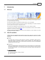
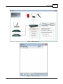
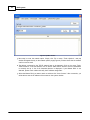
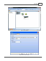
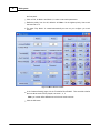
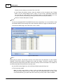
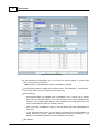
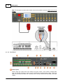
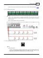
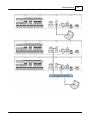
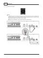
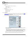
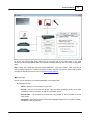
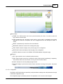
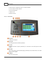
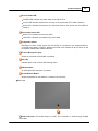
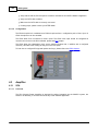
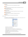
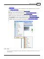
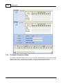
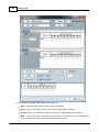
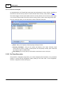
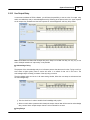
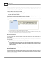
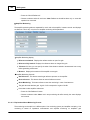
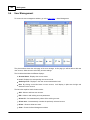
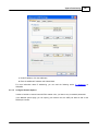
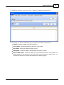
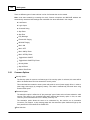
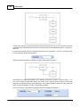
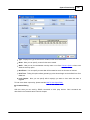
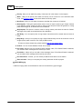
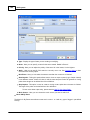
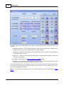
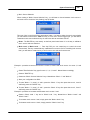
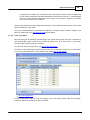
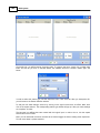
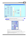
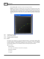
160
DIVA system
Note: Each message have an individual level setting, so each message could have a different level.
Keep in mind that the message level cannot be set differently for each zone.
5.2.8
Set up Front Panel Message
There are three message button on the front panel: Evacuation, Alarm and Test. In order to assign play
message events to those buttons, follow the next steps.
Access the front panel setup window by clicking on the Front Panel Setup button in the master page,
see below.
© 2012 ATEÏS
System Functionality
161
At the left of the window, you will find the button name. You can set an event for only one button, two or
all.
In the corresponding line, click on New to assign a new play message event to the button or
choose an existing one using the drop-down menu accessible by clicking in the Name cell. Event
created is by default named Event X.
Click the Edit button to enter the play message event window, see below.
© 2012 ATEÏS
162
DIVA system
For all the settings available, please refer to the following list:
Type: Display the type of event you are creating or modifying
Name: Here you can specify a name for the event created. Default is Event X
Priority: Here you can adjust the priority of the event. 20 is the lowest, 0 is the highest
Attrib.: Here you can specify if this event is a security one or not and if it is an evacuation event
or not. See Common Option to learn more about the security option
© 2012 ATEÏS
System Functionality
163
Next Event: Here you can select the event to start after the current one is finished
Start Impulse: Ticking this option allows user to close an output contact (Logic Output channel)
in two different manner. Static will close it until the event stop and Pulse will generate a closing
pulse whose length can be defined from 50 to 60000 ms.
Stop Impulse: This option is used to create a closing contact pulse when the event is finished.
The length of the pulse can be defined from 50 to 60000 ms.
ACK Relay: Here you can set the closing of a Logic Output Channel relay as soon as zones
where an event has to be played are freed from higher priority events.
Busy Relay: Here you can specify an Logic Output Channel relay that will be closed as soon as
a higher priority event is playing in common zones. To learn more about output relay, please read
the How To Use Output Relay.
Message: By using the drop down menu, you can select, in the list of stored message, a
message to assign to the event
Play Mode: By ticking continuous, the message will be played until a trigger happen. You can
also specify a number of repeat time.
Conflict: You can choose between Cancel All or Coexist
Repeat Time: If continuous not ticked, you can choose a number of time this event will be
repeated
Pre-define Zone: Here you can specify the pre-define zone(s) where the message will be played
Zone Selection: Here you can specify the zone(s) where the call will be played
OK: Will accept the current setting and close the window
Cancel: Will annulled the current settings and close the window.
Note: Messages can only be seen if they are a part of the configuration. Reading the message
memory of the DIVA does not put messages in the configuration. You'll have to reverse the
messages in order to be able to use them in the configuration.
5.2.9
Create a Monitorable Button
The surveillance of a contact line, a microphone line or speaker line is based on the same measurement.
An internal voltage source is applied to the input or output terminal. By measuring this tension, it is
possible to know the state of the input or output.
With a normal contact (see picture below), you only will be able to measure two states: Open or
Shorten. Shorten (when contact is closed) forces the voltage source to zero.
© 2012 ATEÏS
164
DIVA system
FigAnnexe 1
In this case, the measurement unit can only detect 0V (closed) or 4.4 V (opened).
In order to have different state measurement like open line and short-circuit we need to add a resistor
network to the end of the line, see picture below.
FigAnnexe 2
Using the resistor Network, the measurement unit can detect 4 different states: 1.3 V, 2 V, 2.7 V and
4.4 V. The 4 states correspond respectively to Shortcut, Closed Contact, Opened contact and Absent
(open line).
According to the FigAnnexe 2, you have a fully monitored line responding to the security norms.
© 2012 ATEÏS
System Functionality
165
5.2.10 Use Scheduler
To access the Scheduler window, go on the menu View -> Scheduler. The window below should appear.
Master: This indicates the device on which the scheduler task will happen.
ID: Displays the ID number of the task.
Name: Display the scheduler task name. This name can be entered in the scheduler task
window.
Enable: Indicates if the task is enable or not (ticked means enable).
Occurrence: Displays the way the repeat mode has been set for the task.
Start: Displays the date and time at which the task starts.
End: Displays the date and time at which the task stops. Note: if the task is a Single task, start
time and end time will be the same.
Target: Display which event is affiliated to the task.
Select All: Allows to instantaneously select all the tasks from the list
Select None: Allows to instantaneously deselect task selected from the list
Del: Allows to delete selected task from the list
Add: Allows to add a new task to the scheduler
Edit: Allows to edit one task parameters
Close: Close the scheduler window.
How to set a task:
© 2012 ATEÏS
166
DIVA system
To add a scheduler task, click on the Add button in the scheduler window. Then the Scheduler Task
window will pops up.
General:
Specify a name for the task. Default name are Scheduler Task X.
Tick the “Enable” option in order to make the task available.
Trigger Event:
In the trigger event, you will find a list of all events that are existing in the current configuration.
You can edit one existing event by selecting it in the list and then click the Edit button
Select one in the list or create a new event. Once the event is selected, click on the select button
to affiliate the event to the task that is created
Select if it is a Single occurrence task or a Cycle task. For Cycle task, see picture below.
Occurrence:
You can choose the way the scheduler task will be repeated. The scheduler offers yearly repeated
event, monthly, weekly, daily, hourly and minutely. The weekly option offers days of the week
activation options, see below.
© 2012 ATEÏS
System Functionality
167
Range: here you can specify the date and time for the first occurrence of the scheduler task. You
will also specify the way the task will end: no end, end after a certain amount of repeated time or
end at a specific date and time.
To create a scheduler task, follow the next steps:
o Choose the way the scheduler task will be repeated: every minutes, hour, day, week, month
or year. If week, choose the weekday.
o Set a date and time for the scheduler task.
o Set the end of the task:
No End: task will happen every hour, day, week, month or year from the date and hour
selected and will be repeated until the user delete the task.
Number of times: task will happen for a certain number of hour, day, week, month or year
from the date and hour selected. Example: if set every day, then 3 number of times, the
task will happen the first day set and the two next day at the same hour.
End by date: task will happen each hour, day, week, month or year for a certain period
(can be several hours, days, weeks, etc.). For this option, you will have to specify an end
time.
o Make sure the enable option is ticked.
o Press OK
o Your task will be displayed as follow in the scheduler window.
© 2012 ATEÏS
168
DIVA system
5.2.11 Use Logic Inputs
Logic inputs are a way to start any type of event with an external trigger. They are separated in three
different types:
Normal Logic Inputs:
The eight normal logical inputs are simple logical inputs with no
© 2012 ATEÏS
System Functionality
169
monitoring options.
Evacuation Inputs: The nine evacuation inputs can be used as simple logical inputs as well as
monitored logical inputs. Monitoring type are on contact or voltage UGA. In contact monitored
mode and using a resistor network, the measurement unit can detect 4 different states: 1.3 V, 2
V, 2.7 V and 4.4 V. The 4 states correspond respectively to Shortcut, Closed Contact, Opened
contact and Absent (open line). The voltage UGA monitoring mode is based on polarizing the input
with an external 24V source.
External Fault Inputs: External Fault Inputs are used to put DIVA into security mode.
In order to avoid any sensitivity issue like unwanted triggering of input, you can set a response time on
either Normal Logic inputs or Evacuation Inputs.
This response time act like an activation delay, it means that the trigger signal should be at least as
long as the response time to activate the corresponding logic input. Response time range is from 0ms to
5000ms. The way to configure event for all logic inputs' type is identical. Please read the few next step
to know how to associate an event to a logic input:
Click on the "Start" button under "Event Setting". The Events Selection window will be open, see below.
On the left side, you will find the list of existing event. To create a new event, simply click on New under
Event. As soon as you click on the New button, the software will ask to choose a event's type, see
below.
© 2012 ATEÏS
170
DIVA system
In order to select an event's type, use the drop-down menu. Then click OK. After you have press OK,
you will return to the Events Selection window.
To edit your new event settings, select it by clicking on the right line and then click Edit. Note: don't
click in the square selector.
The corresponding event's type window will pop up. After your event settings are complete, click OK.
The last step is to affiliate the event created with the logical input. In order to do so, tick the square
selector and click on insert.
Note: you can associate more than one event to an external trigger as well as creating event sequences.
To learn more about it, please read this.
5.2.11.1 Normal Logic Inputs
To access the Logic Inputs window, go to the menu View -> Logic Inputs. Then click on the Normal
Logic Inputs tab.
Name: Here you can specify a name by simply clicking in the box.
Normally Close/Open: Here you can specify the behaviour of the inputs. Normally closed
means that the contact is closed in neutral position and reciprocally normally open means that
© 2012 ATEÏS
System Functionality
171
the contact is open in neutral position.
Latch Mode: By ticking this option you will set the contact to be in latch mode. It means that
you will need on trigger to open/close the contact and one more trigger to get it back to the
neutral position.
Event Setting: By clicking start you will be able to associate an event to this input.
5.2.11.2 Evacuation Inputs
Evacuation input have been design to offer monitoring on logical inputs as well as UGA mode, even
though they can be used as normal logic inputs, in order to provide an higher security level for external
trigger.
Name: Here you can specify a name by simply clicking in the box.
Normally Close/Open: Here you can specify the behaviour of the inputs. Normally closed
means that the contact is closed in neutral position and reciprocally normally open means that
the contact is open in neutral position.
Latch Mode: By ticking this option you will set the contact to be in latch mode. It means that
you will need on trigger to open/close the contact and one more trigger to get it back to the
neutral position.v
Monitor: By ticking this option in contact or UGA monitoring mode, you will define an input as a
monitored logical input.
Event Setting: By clicking start you will be able to associate an event to this input.
Monitor Mode: With the drop down menu, you can choose between contact monitoring mode or
UGA mode. Contact monitor mode implies the use of an resistor network on a contact, see How
To Create a Monitorable Button. The UGA mode is based on polarizing the input with an external
24VDC source provided by external devices.
Note: The UGA mode is an alternative way of using contact. It does not offer real monitoring behaviour
and does not increase security.
© 2012 ATEÏS
172
DIVA system
5.2.11.3 External Fault Inputs
As explained before, the External fault Inputs have been implemented in order to offer the possibility to
force DIVA to enter his security mode. For more information about security mode, please read this.
The external trigger of those inputs should come from security devices such as security power supply.
You can also use those input to force DIVA into the security mode in order to save energy during night.
Like any of the logic inputs, you can associate an event to External Fault Inputs.
Name: Here you can specify a name by simply clicking in the box.
Normally Close/Open: Here you can specify the behaviour of the inputs. Normally closed
means that the contact is closed in neutral position and reciprocally normally open means that
the contact is open in neutral position.
Event Setting: By clicking start you will be able to associate an event to this input.
5.2.12 Do Phase Evacuation
Using the Evac configuration setup allows you to easily designed phase evacuation or any evacuation
scheme. To access the Evac Configuration matrix, please go in the menu View -> Evac Configuration.
The Evac configuration window should pop up.
© 2012 ATEÏS
System Functionality
173
The purpose of the Evac configuration is to use 2 different play message events (Evac and Alarm) and to
use them with Evacuation input in order to create phase evacuation.
Events: When using Evac configuration option, you will have to create two dedicated play
message events (Evac and Alarm).
Edit Evac Event: allows the creation of the evacuation "play message" event.
Edit Alarm Event: allows the creation of the alarm "play message" event.
Once one of this button is pressed the following event edit window is opened.
© 2012 ATEÏS
174
DIVA system
Type: Display the type of event you are creating.
Name: Here you can specify a name for the event created. Default is Event X.
Priority: Here you can adjust the priority of the event. 20 is the lowest, 0 is the highest.
Attrib.: Here you can specify if this event is a security one or not and if it is an evacuation event
or not. See Common Option to learn more about the security option.
Start Impulse: Ticking this option allows user to close an output contact (Logic Output channel)
© 2012 ATEÏS
System Functionality
175
in two different manner. Static will close it until the event stop and Pulse will generate a closing
pulse whose length can be defined from 50 to 60000 ms.
Stop Impulse: This option is used to create a closing contact pulse when the event is finished.
The length of the pulse can be defined from 50 to 60000 ms.
ACK Relay: You can specify here an logic output channel that will be closed when the event is
active.
Busy Relay: Here you can specify an Logic Output Channel relay that will be closed as soon as
a higher priority event is active in one of the pre-define zones.
Set the play message event option to suit your needs.
The bottom part of the Evac Configuration form is dedicated to create the phase evacuation. After having
enabled an evacuation input, you have to define in which zones the messages will be played.
For each evacuation input (CH1 to CH8), select the routing of Evac event and Alert event by
clicking into the boxes, see next picture
Define the corresponding Evacuation Input activation mode, see chapter "How to Evacuation
© 2012 ATEÏS
176
DIVA system
Inputs"
Note: only eight of the nine DIVA evacuation input are accessible from the Evac Configuration
option. The ninth evacuation input is reserved for evacuation reset.
The next picture shows, as an example, a finished configuration.
The configuration above will act as follow:
Evacuation Input 1 (CH1) activated: The Evac message is played in zone 1, Alert message in
zone 2.
Evacuation Input 2 (CH2) activated: If CH1 still active, the Evac message is played in zone 1
and 2, Alert message is played in zone 3.
Evacuation Input 3 (CH3) activated: If CH1 and Ch2 still active, the Evac message is played in
zone 1, 2 and 3, Alert message is played in zone 4.
Evacuation Input 4 (CH4) activated: If CH1, CH2 and Ch3 still active, the Evac message is
played in zone 1, 2, 3 and 4, Alert message is played in zone 5.
© 2012 ATEÏS
System Functionality
177
5.2.13 Use Output Relay
In some event windows of DIVA software, you will have the possibility to set an action for output relay
and/or to enable busy relay or acknowledgement relay. Referring to the picture below, the upper squares
are for output relay activation and the lower squares for acknowledgement and busy relay states.
Note: DIVA Master and Slave offer 8 output relay each. Keep in mind that one relay can only rely to one
action. Multiple activation of output relay is not possible.
Acknowledge Relay
The purpose of the Acknowledge relay is to indicate to persons that the event is active. Trying to call in a
zone where a higher priority event is active will result in a refusal of that call in this zone. The
acknowledge relays will keep you aware of that by being not active.
The acknowledge relay can be set in all event setting window, follow the next steps to activate and set
an acknowledge relay.
Tick the check box in order to enable the acknowledge relay option.
Select on each device (master and/or slaves) the output channel that will be used as acknowledge
relay contact. Note: multiple output channel can be selected for an event.
Busy Relays
© 2012 ATEÏS
178
DIVA system
The busy relays have been made to inform user that there is already an higher priority event active in at
least on zone of the event. The lower priority event won’t be able to start in “cancel all” mode and can be
started in non-common zone in “coexist” mode.
In order to make it clearer, here is an example.
Event 1: play message, priority 4, busy relay CH1
Event 2: play message, priority 1
When Event 2 is active, the output relay CH1 is active. It informs that an higher priority event is active
and that Event 1 wont' be played or partially be played if it is activated.
The Busy relay can be set in all event setting window, follow the next steps to activate and set an Busy
relay.
Tick the check box in order to enable the busy relay option.
Select on each device (master and/or slaves) the output channel that will be used as busy relay
contact. Note: multiple output channel can be selected for an event.
Active at Start Relays
The Active at Start relay, named start impulse, will allow the activation of an output channel when an
event is started.
The start impulse relay can be set in all event setting window, follow the next steps to activate and set
an start impulse.
Tick the check box in order to enable the start impulse option.
Choose between the pulse mode or static mode. Pulse mode will generate a contact pulse for the
time set, range from 50ms to 60000ms. Static mode will activate the output contact for the entire
duration of the event.
Select on each device (master and/or slaves) the output channel that will be used as Start
Impulse contact. Note: multiple output channels can be selected for an event.
Active at Stop Relays
The Active at Stop relay, named Stop Impulse, will allow to activate an output channel when an event is
stopped. The stop impulse relay can be set in all event setting window, follow the next steps to activate
and set an Active at Stop relay.
© 2012 ATEÏS
System Functionality
179
Tick the check box in order to enable the relay.
Set the contact pulse length, range 50ms to 6000ms.
Select on each device (master and/or slaves) the output channel that will be used as Start
Impulse contact. Note: multiple output channels can be selected for an event.
Use Bypass Relay
The bypass relays are independent of events. The goal of bypass relay is to close/open a relay when
some zone(s) are occupied with a type of source.
In order to set a bypass relay, follow the next few steps:
Go in menu View -> GPIO -> Bypass Relay tab
o Channel 1 to 8: Correspond to the output channel.
o Activations: Specify if the contact will be closed when active or opened when active.
o Settings: By clicking on the edit button, you will enter the zone/source matrix.
© 2012 ATEÏS
180
DIVA system
o Link by: By clicking the "a" icon, it will open a display in which you will find the CH X already
existing trigger (Bypass, Busy, Acknowledge, Active at start or active at stop relay).
Click on the Edit button of the channel you want to use as a bypass relay, the following matrix
window will pop up, see below:
With the bottom left drop-down menu, you will be able to specify for each source type (Music 1,
Music 2, Normal message, Evac message, PSS) the zone in which the source has to be routed
to activate the relay.
Click OK to validate.
Note: for each of the 8 output relays, you can specify multiple zone-source routing for the relay
activation.
5.2.14 Use Monitoring
In order to access and activate zones monitoring and/or amplifiers monitoring, click on the monitoring
button under DIVA icon in the master window, see below.
© 2012 ATEÏS
System Functionality
The monitoring window is then opened, see below.
© 2012 ATEÏS
181
182
DIVA system
General options:
18K/20K Monitor Setting
o Frequency (Hz): Here you can choose 18K or 20K.
o Active Mode: There are two options for the monitoring process: "Periodic" and "Only once a
day". In order to comply with EN54 standards, the monitoring active mode should only be
Periodic. If the "Only once a Day" option is chosen, you have to specify at what time the
monitoring process will be activated with the "Active Monitor Period".
o Monitoring Period: If front knob attenuators are in use and if the attenuation value is -16 or 20 dB, the monitoring for accuracy purposes will only occur every Monitoring period. By
default, this option is set to 90s. Be carefull that for standard compliancy, this setting should
be manipulate with care and accordance to standard.
o Continuous Mode: If it's enable, it keeps monitoring.
o Active Monitor period: Day time where the monitoring "Only once a day" will take act.
1K Monitor Setting
o 1K Monitor Enable: If it's enable, you can check both Amplifier and Monitoring. Note: The
© 2012 ATEÏS
System Functionality
183
1K monitoring will cause high pitch sounds.
Leakage Detection Control:
o M/S Amplifier Share: If there are more than one devices, this box should be ticked.
Monitor Control
o HW Observer Mode: If enabled, this options in combination with the "Monitor device" dropdown menu allows to block the monitoring process on one device. This option has been
designed only for commissioning and maintenance purposes.
Warning: as soon as maintenance tests are finished, you have to disable the "HW
Observer Mode" option.
o Current Monitor Target ID: Displays the current monitored device. In "Periodic" monitoring
mode, you should see the display going from Master DIVA to each Slave unit. In "HW
Observer Mode", you should only see the device selected with in "Monitor device" drop-down
menu.
Zone Monitoring
Zone Monitoring display:
Zone: Displays the zone number.
ReferenceA (Ohm): Displays the value taken as reference for line A of one zone.
ReferenceB (Ohm): Displays the value taken as reference for line B of one zone.
RefereneA/B (Ohm): Displays the value taken as reference for A and B in parallel.
Connected Source:
Amplifier, VO3).
Display the source connected to one zone (Voice Amplifier, Music
Tolerance (%): Here you can specify the tolerance wherein measurement has to stay before
generating a fault state.
Measure (Ohm): Displays the real time measurement of A and B in parallel.
Diff (%): Displays the difference in percent between Reference A/B and Measure.
Zone Monitoring Controls:
Get Reference: This button start the get reference process for one zone at a time
Get all Reference: This button start the get reference process for all zone
Reset Reference: This button allows to reset all reference stored
Reset Monitoring: This button allows to reset the monitoring in case of maintenance
Procedure to make references for one zone, please follow the next steps:
o Select a zone by clicking on the corresponding line.
o Press the "Get Reference" button.
o Choose a tolerance value.
Procedure to make references for all zone, please do so:
© 2012 ATEÏS
184
DIVA system
o Press the "Get All Reference".
o Choose a tolerance value for each zone. Note: References should be taken only on zone with
speaker line connected.
Amplifier Monitoring
The amplifier monitoring tabs are separated for music and voice amplifier, however controls and displays
are identical. This is why only the voice amplifier monitoring will be presented.
Amplifier Monitoring display:
Reference unloaded: Displays the reference taken as open line gain.
Reference fully loaded: Displays the reference taken as charged line gain.
Tolerance %: Here you can specify the value of the tolerance wherein measurement has to stay
before generating a fault state.
Measure: Displays the measure of the amplifier current gain.
Amplifier Monitoring Controls:
Get Reference: This button start the get reference process on the amplifier.
Reset reference: This button allows to reset all reference stored.
Reset Monitoring: This button allows to reset the monitoring in case of maintenance.
The gain value are absolute gain. A gain of 100 correspond to a gain of 40 dB.
Procedure to take amplifiers references:
o Press the "Get Reference" button
o Choose a tolerance value. Note: music amp monitoring tab offers exactly the same displays
and controls.
5.2.14.1 Explanation About Monitoring Process
The monitoring can be split into 2 different parts: Line monitoring (zones) and amplifier monitoring. Line
monitoring is based on impedance measurement and amplifier monitoring on amplifier's gain
© 2012 ATEÏS
System Functionality
185
measurement.
Amplifier monitoring:
The amplifier monitoring used a pilot tone at 18kHz or 20kHz that is adapted to pull out 2 Vrms. By
measuring the output signal of the amplifier and computing it in the DSP, we can adjust the level of
the pilot tone. The adjustment of the pilot tone is related to the amplifier gain and can directly inform
us on the gain value.
The gain variation are measured constantly and compared to a gain references value.
Below, you can find a bloc schematics for Voice amplifier channel.
Note: If the amplifier gain is changed after the reference has been taken, the pilot tone level could
increase dramatically.
Example: the reference is taken with a gain of 1, the pilot tone will be set to 2Vrms. Then if the
amplifier gain is increased to 100, the pilot tone level will be raised to 200Vrms!!!!
To avoid problems, the gain of both Music and Voice amplifier should be set to same value and in
preference to the maximum gain value.
There is three different channel for monitoring: Voice amplifier channel, Music amplifier channel and
VO3 channel.
VO3 is channel that only generate the pilot tone in case no amplifier channel is in used.
Zone Monitoring:
Zone Monitoring is based on three different reference values: Line A, Line B and Line A/B. Reference
for Line A and Line B are Line A and Line B direct impedance measure. Reference Line A/B
correspond to the Line A and B in parallel.
Line A = Za
Line B = Zb
Line A/B = 1/((1/Za) + (1/Zb))
To ensure a high precision measure, for each reference (A, B and B/A) three values are taken.
Example: Line A: VO3 channel, Line A: Voice amp channel and Line A: Music amp channel. In the
references display, the value will change according to channel routed on each zone.
Example: Zone 1 Line A ref:
© 2012 ATEÏS
186
DIVA system
VO3: 530 Ohm
Voice: 545 Ohm
Music: 540 Ohm
When music is routed to zone 1, the display shows 540 Ohm. As soon as a Voice call is routed on
the zone 1, the display will show 545 Ohm. If no music or no voice call is routed on zone 1, the
display will show 530 Ohm.
The schematics above explain how the different channel are routed to zone(S) and how the
impedance measurement is made. Signal VSix, VSgx, ISix and ISgx are computed into DSP and
then compared to reference values.
The real measure is made with A and B in parallel. In the case the measured value differs from the
reference value, Line A will be measured independently and compare to the Line A reference and the
same process is done for Line B.
5.2.15 Use Presets
The DIVA application allows user to create different preset that can control audio settings (audio levels
on each source, hi-pass and low-pass filter settings, compressor-limiter settings). Loading a preset will
change the current audio settings; you can adjust audio settings for different situation using several
presets.
In order to create a preset, please follow the next few steps.
To create a new preset, click on the Add button in the preset toolbar
By default, the preset created is named untitled X. You can rename it by clicking on the Name
button in the preset toolbar.
© 2012 ATEÏS
System Functionality
187
To relate a setting to a preset, right click on the control and link it to a created preset in the list.
The value set when linking a control to a preset will be saved to the preset.
To load a preset, select the preset from the list in the preset toolbar and click on the load button.
© 2012 ATEÏS
188
DIVA system
To modify a setting in the preset, load the preset, change the value and then save the preset with
the save button in the preset toolbar.
Presets can be loaded using the load preset event. To learn more about the load preset event, please
read this.
Note: a control can be affiliated to several preset, to do it assign the control to all the preset.
5.2.16 Manage Log File
The Log File records all incident and events happening on the DIVA system. DIVA has been designed to
record up to 2047 occurrences.
The Log File can be accessed and managed by either the front panel or inside of the software.
From Front Panel
From the front panel, you can read the Log File and clear the Log File.
To read the Log File:
From the FUNCTION MENU:
Use arrow keys to access the LOG RECORD menu.
Press OK.
Use arrow keys to display different Log Files occurrences. Note: first occurrence displayed
is the latest log file
occurrence:
o Log File occurrence are displayed in the following way:
First line, occurrence number and date: "XXXX yy/mm/dd"
Second line, time and status (Start, end): "hh:mm:ss Status"
Press OK.
Log File entry is displayed in plain text on two lines.
Press Up arrow or Down Arrow keys to go to the previous/next log file occurrence.
Press ESC to go back to the Log File menu.
For a complete list of Log File entry, please read the Log File Messages List chapter.
To clear the Log file:
From the FUNCTION MENU:
Use arrow keys to access the LOG RECORD menu.
Press OK.
Use arrow keys to access "Clear Log Files" submenu.
© 2012 ATEÏS
System Functionality
189
If you want to delete the Log Files, Press OK.
You will be asked for validation: "SURE? OK/ESC".
If Yes, Press OK.
If No, Press ESC.
From Software
In the software, the log file is accessible either by the menu View -> System Status -> Log or
directly by moving the mouse on System Status icon in the Property Control Section bar, see
below.
In the Log tab, you will be able to export, read Log File and clear the Log File display.
Export Log: Exports the Log File into .txt file.
Clear: Deletes the entire Log File content.
Read log: Clears the Log File software display.
Log Record Limit: Specify the number of Log file occurrence displayed.
In order to read the log file entries, click on the "Read Log" button. Note: to be able to read the log
file, you have to be real time connected. If an incident is recorded, it will appear as shown in the
following picture.
No: Displays the number of the log file occurrence. No 1 is the youngest.
Message: Displays the log file message corresponding to the record. For more information
about Log file messages, please read this.
Start/End: Displays if the incident started or ended.
Date: Displays the date at which the event happened.
© 2012 ATEÏS
190
DIVA system
Time: Displays the time at which the event happened.
5.3
Operation
Compile
Compiling your current project will inform you in case of configuration errors or warnings. In order to be
able to store a configuration into DIVA, you will have to compile your project first.
To compile go in the menu: Operations -> Compile or Click on the Compile icon in the compile toolbar
(view picture below) or even type F9.
On the Status Bar, you can permanently see the compile status of your project:
Compiled: Means the current state of your project have been checked
Not Compiled: Means that your current project has not been checked
Store
The store command, menu Operations -> Store or the Store shortcut or even F8, open the store window,
see below.
To start storing, click on the "Store" button.
A timeline display the status of the process. The different states of the store process are written in the
© 2012 ATEÏS
System Functionality
191
Store Status Area.
If not already log in, DIVA software will ask you to enter a valid user name and password.
Once the store process is finished, you will be prompt to:
Connect to DIVA? choose Yes or No
Enable Audio on DIVA? choose Yes or No
Reverse
The reverse command allows to download from DIVA to the software the current configuration stored into
DIVA.
To start the reverse process, go to the menu Operations -> Reverse or use the Reverse Shortcut
on the compile toolbar
Click Reverse, you can follow the advancement of the process on the timeline display The reverse
window will be open, see below.
© 2012 ATEÏS
192
5.4
DIVA system
User Management
To access the user management window, go on the menu User -> User Management.
The picture above shows the main page of the user manager. In this page you will be able to add new
user account, delete account and modify account settings.
The List below describes the different displays:
Account Name: Displays the account name.
Level: Displays the corresponding user account level.
Authority Level: Displays in the user account authorization level.
Hint: By clicking on the Hint button on user account, it will display in plain text the right and
restriction for the account.
The list below explains how the button works:
Add: Allows to add new user account.
Edit: Allows to edit existing account parameters.
Select All: Can instantaneously select all the existing account.
Select none: Instantaneously unselect the previously selected account.
Delete: Allows to delete accounts.
Close: Closes the User Management window.
© 2012 ATEÏS
System Functionality
193
Note: by default, four user accounts are created corresponding to the four user level existing in DIVA
application.
Add User Account
To add a new user account, simply click on the add button. A New Account pop-up window like the one
below will appear.
Enter the user name for the new account.
Click next.
Enter a password for the account created.
Confirm password.
Click Next to continue the process of creating an account.
Click Back to go back to the previous step.
© 2012 ATEÏS
194
DIVA system
Select an Level for this user account, explanation on user level can be found here.
Click Finish to finish the process.
Click Back to go back to the previous step.
Delete User account
Select an account in the list of the User Management by ticking the corresponding check box.
Click on delete.
it will prompt you "Delete User account?", click OK to delete or Cancel to stop the delete
© 2012 ATEÏS
System Functionality
195
process.
Explanation on User Level
In order to comply to the European standard EN 54-16, the user level have been set as described:
Level 1 is the lowest level.
o Level 1 has the right to use real-time software control (music level, filters and PEQ), real-time
front panel control (music level, speaker level) and indicators.
o Level 1 is always accessible without password.
o Can do reverse procedure and connect from software.
Level 2 is defined to be for person having a specific responsibility for safety.
o Level 2 has all right, except:
Storing config + messages
Change Ethernet settings
o To enter level 2, a password is needed.
Level 3 is for specific maintenance operator and trained persons. Level 3 has all the right of level 2.
o o Store a new configuration file
Manage messages
Maintenance operation
o To enter level 3, a password is needed.
Level 4 is for authorized by the manufacturer to either repair the unit and/or alter its firmware. Level
4 has all
o the level 3 rights.
Update firmware
Repair
o To enter level 4, a password is needed.
5.4.1
Enter Password
For process like storing and updating, you will need a username and a password, see How To Use User
Management.
There are two different way of connecting to your account, from front panel or from software.
From front panel:
When trying to attempt protected operations, you will have to enter you user name and your
password.
o Use the arrow keys to select the right letter or number.
© 2012 ATEÏS
196
DIVA system
o click OK.
o enter the next letter or number repeating the same procedure
o Once you have enter the right user name, press once the down arrow key to find "APL".
Press OK, this will validate you entry.
o DIVA will ask to enter your password, repeat the same procedure to enter password.
From software:
You will be automatically login after first store, update, network options change, ethernet
settings change.
Effectively, DIVA software will ask you to enter a valid user name and password and will
remember your username and password until you exit or logout of the current configuration file.
To log out, go to the menu User -> Logout.
Default User Name and Password are:
ATEIS4 and ATEIS4 (highest level)
ATEIS3 and ATEIS3
ATEIS2 and ATEIS2
ATEIS1 and ATEIS1 (lowest level)
Note1: Username and password entry are not case sensitive, they are always filled in capital letters.
Note2: In order to have to highest level control, please use the ATEIS4 default account.
Note3: Configuration won't be stored if no level 4 account exist.
5.5
Device Management
5.5.1
Search and Settings
5.5.1.1
Set Computer Network Parameters
Before attempting to connect to a DIVA through TCP/IP, make sure that your computer Ethernet
settings are corresponding to the one in DIVA. You have two possiblities to make them compatible,
either change manually change the DIVA Ethernet settings or adapt your computer Ethernet settings.
DIVA's default ethernet settings:
IP address: 192.168.100.100
Subnet Mask: 255.255.255.0
Gateway: 192.168.100.1
To check and/or modify your computer network settings, follow the next steps:
This step by step procedure is only accurate for Windows XP.
From Start, go to Settings, then Control Panel.
From the Control Panel, double click Network Connections icon.
© 2012 ATEÏS
System Functionality
197
If you have created a Local Area Connection and want to modify it, right click the icon, highlight
Properties.
Note: choose the Network connection/card you'll use.
Highlight Internet Protocol (TCP/IP) and then click on properties. It will display the following
Internet Protocol (TCP/IP) Properties dialog box:
© 2012 ATEÏS
198
DIVA system
Select "Use the following IP Address" and enter values for IP address, Subnet Mask, Gateway. If
you are not sure what settings you should apply, please ask your network administrator.
Select "Obtain DNS server address automatically", this would work most of the time. In windows
for one network connection/card, you can specify several IP addresses.
In the Internet Protocol (TCP/IP) Properties dialog box, click on "advanced".
© 2012 ATEÏS
System Functionality
199
Under IP address, click the Add button.
Enter the additional IP address and Subnet Mask.
For more information about IP addressing, you can read the following article: IP addressing on
Wikipedia.
5.5.1.2
Configure Network Options
In order to be able to communicate with DIVA master units, you have to set your network parameters.
In the Network options page, you can specify your network card, the UDP port value as well as the
RS232 port number.
© 2012 ATEÏS
200
DIVA system
After all the network options have been set, please refer to the How To Set IP Address paragraph.
Note: changing the UDP port value should be done only with extreme care. Wrong settings could make
the system unavailable on the network. It is highly recommended to use the default UDP port setting.
5.5.1.3
Search Device
To perform a device search, go to the menu Tools -> Device Search. The Device search window will
open, see below.
© 2012 ATEÏS
System Functionality
201
Buttons explanation:
Edit Search Group: Allows to define IP addresses group in which to perform the search process
TABs: You have access to two different search tabs, on to search for master DIVA unit and one
to search for Ethernet PSS devices.
Search: Starts the search process. A progression bar indicates when the search is finished
Auto Connect: Allows the connection to a master DIVA that have been found. Select a master in
the list by just clicking on the corresponding line.
Note: attention do not select Enable DHCP when clicking on the line, it could cause connection
problem.
Manual Connect: Allows to quickly connect to a known master DIVA IP without doing the
search process
Close: Closes the Device Search window.
Before starting to search for devices connected to an IP network, search group have to be defined.
Please follow the next few steps:
© 2012 ATEÏS
202
DIVA system
Click on the Add button, the Edit Search Group window appears
Enter a name for the group
Enter an IP addresses range, enter the start address and the end address
Click OK
In the Search Group window, you can manage groups by deleting them or edit them.
To delete or edit one group, tick the corresponding check box and click on either the Delete button or
the Edit button.
Click on the Search button to start the search process.
Click on the corresponding device line.
Click on the Auto Connect button. A window pop up indicates the connection status.
You can also manually enter the DIVA IP address by click on the Manual Connect button. This avoids
using the search process if the IP address of the device is known.
To search the network for Ethernet PSS devices, go on the Ethernet PSS tab.
© 2012 ATEÏS
System Functionality
203
Once an Ethernet PSS will be found, you will be able to use it in the configuration, see How to Use
Ethernet PSS.
5.5.1.4
IP Address
From the front panel of DIVA, you can change the address from the LCD menu display. In order to do
this, please read this.
DIVA's default IP address is 192.168.100.100
IP, Submask and gateway address can also been changed from the software by going in the device
search menu:
Tools -> Device Search. Note: you should be connected to the DIVA unit to be able to operate Ethernet
setting changes.
© 2012 ATEÏS
204
DIVA system
To modify the IP settings of the device, please follow the next steps:
Click on the corresponding device Modify button.
It prompts you either if you want to continue or to cancel the modifying IP process.
Click OK, the Modify Device IP window appears
© 2012 ATEÏS
System Functionality
205
In this window you can enable DHCP by ticking the corresponding check box
Enter the IP address value
Enter the Subnet Mask value
Enter the Gateway value
Click OK
If not already logged in, it will prompt you to enter an username and password
System will reboot automatically
Note: you have to keep in mind that setting TCP/IP parameters not related to the one set for your
network card, could lead to communication problems.
5.5.2
Verify Diva Versions
Before checking the DIVAs firmware versions, you should connect to the machine trough TCP/IP, see
How to Search Device chapter.
In order to verify that the current software correspond to the DIVAs' units firmware, please follow the next
steps:
Go in the menu "Help"
choose "Version"
Then the following window should pop up:
© 2012 ATEÏS
206
DIVA system
Click the "Read" button
The "Compatible Version" displays shows the firmware version that will be working with the application
software version currently installed. "Current Version" displays shows the current DIVA units firmware
version.
If one unit is in a incompatible version, the version number will be red highlighted. In that case, an update
has to be done.
5.5.3
Update
The update command allow user to upgrade the DIVA internal software to the version delivered with the
Windows based software. This is one of the first things to do when starting a new project or using a
DIVA unit for the first time. This could really save time and avoid communication and store problem.
© 2012 ATEÏS
System Functionality
207
To activate this command, go the menu: Tools -> Update. The Update window will pop up:
On this window, you will find 4 different tab which correspond to 4 different update process:
UPDATE: Allows the update of the DIVA master unit.
Slave update: Allows the update of all slave units in the system.
PSS Update: Allows the update of the PSS console.
PSM Update: Allows the update of the PSM/CD16 microphone consoles.
Ethernet-PSS Update: Allows the update of all the Ethernet PSS found in the network. To
perform update you need to have the user level 4 rights. Once clicked on the update button, you
will be prompt to enter an username and password if not already logged in.
© 2012 ATEÏS
208
5.5.3.1
DIVA system
Update Master Unit
Open: Here you can specify the path of the MCU update file. By default, the path specified
correspond to the software release version.
CRC: Displays the CRC check code corresponding to the firmware. This CRC code can be
compared to the one that can be read from the front panel.
Update: Will start the update process.
Close: Closes the window.
Timeline display: Shows the update process progression.
General Display: Displays the update information.
© 2012 ATEÏS
System Functionality
5.5.3.2
209
Update Slave Unit
Open: Here you can specify the path of the MCU Slave update file. By default, the specified path
corresponds to the software release version.
Update: Will start the update process.
Close: Closes the window.
Timeline display: Shows the update process progression.
General Display: Displays the update information.
All the slaves in a system can be updated at once. Choose the Slave unit you want to update by
checking the corresponding check box.
© 2012 ATEÏS
210
5.5.3.3
DIVA system
Update PSSG2
Open: Here you can specify the path of the PSSG2 update file. By default, the path specified
correspond to the software release version.
Update: Will start the update process.
Close: Closes the window.
Timeline display: Shows the update process progression.
General Display: Displays the update information.
© 2012 ATEÏS
System Functionality
5.5.3.4
211
Update PSM/CD16
Open: Here you can specify the path of the PSM/CD16 update file. By default, the specified path
corresponds to the software release version.
Update: Will start the update process.
Close: Closes the window.
Timeline display: Shows the update process progression.
General Display: Displays the update information.
© 2012 ATEÏS
212
5.5.3.5
DIVA system
Update PSSG2E
Open: Here you can specify the path of the PSSG2-E update file. By default, the path specified
correspond to the software release version.
Update: Will start the update process.
Close: Closes the window.
General Display: Displays all the Ethernet PSS information as well as the update progression.
5.6
Event Management
As briefly explained before, the DIVA action is based on event philosophy. Each action is described in
event. Event can be started by different type of trigger.
The events created by any manner are all listed in the event page window. To access this window, go to
the menu View -> Event.
In the Event window, you can managed all the event created and see the priority hierarchy, next event
called, sequences and calling event.
© 2012 ATEÏS
System Functionality
213
Square Selector: You can select event(s) by ticking the square selector at their right.
ID: The events created are identified with one number, the ID number.
Name: Displays the event's name. You can specify a name for an event when editing the event.
By default the name is set to Event X.
Priority: Displays the priority level of an event.
Security: Displays if the event is a security one or not.
Type: Displays the type of the event.
Next Event: Displays which event is called after this event.
Time: If an event loop has been created, displays the number of time the loop is made.
Link By: Displays the trigger that will activate the event.
Select All: Select instantaneously all events in the list.
Select None: Deselect instantaneously all selected events.
Event Type: Here you can select the event type that you want to create. This have to be made
before press the Add button.
Add: After the event type selection, pressing the Add button will create the new event in the list.
Edit: After creating an event, you will have to edit all its parameters. By clicking the edit button,
you will enter the different event setting windows.
Close: Closes the Event window.
© 2012 ATEÏS
214
DIVA system
There are different types of event and here is a list of all events that can be created.
Note: some event created by accessing the music, fireman microphone and MIC/LINE windows are
automatically named and offer settings that could differ from those described in this chapter.
Load Preset
Logic Output
Command String
Stop Event
Stop Zone
Play Message
Fireman Mic Paging
MIC/LINE Paging
Music ON
Music OFF
Music ON By Zones
Music OFF By Zones
Toggle Music ON/OFF
Toggle Music ON/OFF By Zones
Security Mode
Stop All Event
Silence Zone Event
5.6.1
Common Options
Security Option:
The Security option is common to all event type. If the security option is selected, this event will be
able to be started when DIVA has entered the security mode.
This mode have been created to enter a power safe mode in case of power supply failure, in order to
save energy when supply by emergency battery. This mode is automatically launched when using
External Fault Inputs.
Evacuation Option:
The evacuation option is offered on all "play message" type of event and on all event related to audio
sources. This option is only accessible after having selected the Security option. In fact, an event
could only be an evacuation event if it is already a security one.
The evacuation option allows the event to be understood by the machine as an evacuation
occurrence. For instance, a play message event with the evacuation option defined will light up the
front panel EVAC LED instead of the PAGE LED.
Zone Selection:
© 2012 ATEÏS
System Functionality
215
In many event you will be able to choose some pre-defined zones. Here is the zone selector display
and explanation.
From Left to right and up to down
Master 1: correspond to your project name (master unit plus slave ones)
o All: selects all zones of master and slave(s) units .
Master: means master unit
o All: selects all zone of the master unit.
o 1-8: allows to select independently zone 1 to 8 from a master and/or slave unit.
Cancel All and Coexist options
The Cancel All and Coexist options have been created to manage conflict when two events using
common zones.
The higher priority event always overwrites the lowest priority event in the common zone. But
regarding to the option chosen, the behaviour is different.
To learn more, please read this.
5.6.2
Event Sequence
You can define multiple events by accessing the event window (menu “View -> Event”). In this window,
all the existing events are listed. You can add/delete events.
Before adding a new event, choose in the “Event Type” drop-down menu the desire event’s type. Click on
the new event then “Edit” to be able to set up parameters for this new event.
You can declare event with the same action, like playing a message (even playing the same message).
You just have to give them different names.
The event can be cascaded. An explanation diagram is visible on the next figure.
© 2012 ATEÏS
216
DIVA system
An action like closing a contact could induce to start an event. But as soon as the first event is finished
or stopped, the second event will be launched. The second event could activate the start of a third event,
and so on.
In each event edit page, there is a next event drop down menu, see below. In this menu you will be able
to choose between all the existing events.
Events could also be looped. The diagram on figure below explains it visually.
According to the looping event diagram, when selecting next event for “Event 2”, choose “Event 1”. As
soon as you select an event that is before in the chain, a new “Circular Times” selector is visible just
beside the next event drop-down menu (see below). This selector permits to define how many times the
events’ loop will be repeat or to make it continuously repeating.
This is a quick way to loop different language evacuation messages for example.
© 2012 ATEÏS
System Functionality
217
Once you go back in the event window. You can see multiple information about sequences like the next
event that is called (Next event), the number of time the loop is repeated (Times) and the event or action
that is linked to one event (Link By), see picture below.
By clicking at the right of the Next Event box, you will be able to graphically display the event sequence
or loop, see below.
5.6.3
Event Type
In the Next paragraph, you will fin a description of all the different event that could be found in DIVA
programming.
You will by this way learn how to use them and when to use them.
Load Preset
© 2012 ATEÏS
218
DIVA system
In DIVA, you have the possibility to set preset. To learn more about presets, please read this.
The event load preset can be used as soon as there are existing preset. It allows activating a preset with
different trigger like GPIO or the scheduler.
Type: Displays the type of event that is created, in this case Load Preset.
Name: Here you can specify a name for the event created.
Attrib.: Here you can choose between security event or not. See Common Option to learn more
about the security option.
Next Event: You can specify an event that will be started as soon as this event is finished.
Preset: Here you can specify the preset to be loaded.
Logic Output
As described before, DIVA has 8 output channels that can be commanded by several trigger type. When
using the
Logic Output Event, you can associate to a trigger the closing of an output.
© 2012 ATEÏS
System Functionality
219
Type: Displays the type of event that is created, in this case Load Preset.
Name: Here you can specify a name for the event created.
Attrib.: Here you can choose between security event or not. See Common Option to learn more
about the security option.
Next Event: You can specify an event that will be started as soon as this event is finished.
Hold Time: Ticking this option allows generating a pulse whose length can be defined from 50 to
60000 ms.
Logic Output:
triggered.
Here you can specify which output(s) you want to close when the event is
To learn more about output relay, please read the How To Use Output Relay.
Command String
With this event you can send by RS232 commands to third party devices. Valid commands are
described in the Communication Protocols chapter.
© 2012 ATEÏS
220
DIVA system
Type: Displays the type of event that is created, in this case Load Preset.
Name: Here you can specify a name for the event created.
Attrib.: Here you can choose between security event or not. See Common Option to learn more
about the security option.
Next Event: You can specify an event that will be started as soon as this event is finished.
Starting Command: Here you can type in the command to be sent at the event activation.
Stopping Command: Here you can type in the command to be sent at the event deactivation.
Port Number: Here you have to specify on which RS232 port the command have to be sent.
Stop Event
This event have been created in order to be able to stop any event by the means of a trigger.
© 2012 ATEÏS
System Functionality
221
Type: Displays the type of event that is created, in this case Load Preset.
Name: Here you can specify a name for the event created.
Priority: Here you can choose a priority level for this event.
Attrib.: Here you can choose between security event or not. See Common Option to learn more
about the security option.
Next Event: You can specify an event that will be started as soon as this event is finished.
Stop Event: Here you can select from the existing event list, the event to be stopped.
Stop Zone
The Stop Zones event can interupt every paging, music events in pre-defined zone(s).
Type: Displays the type of event that is created, in this case Load Preset.
© 2012 ATEÏS
222
DIVA system
Name: Here you can specify a name for the event created.
Priority: Here you can choose a priority level for this event.
Attrib.: Here you can choose between security event or not. See Common Option to learn more
about the security option.
Next Event: You can specify an event that will be started as soon as this event is finished.
Zone Selection: Here you can choose in which zones lower priority events will be interrupted.
Play Message
Play message allows starting a message in pre-defined zones after a trigger or starting a message in
zones manually selected. The Play Message event offers the possibility to set an output relay activation.
For more information about use of output relay, please read this.
© 2012 ATEÏS
System Functionality
Type: Display the type of event you are creating or modifying.
Name: Here you can specify a name for the event created. Default is Event X.
Priority: Here you can adjust the priority of the event. 20 is the lowest, 0 is the highest.
© 2012 ATEÏS
223
224
DIVA system
Attrib.: Here you can specify if this event is a security one or not and if it is an evacuation event
or not. See Common Option to learn more about the security option.
Next Event: Here you can select the event to start after the current one is finished.
Start Impulse: Ticking this option allows user to close an output contact (Logic Output channel)
in two different manner. Static will close it until the event stop and Pulse will generate a closing
pulse whose length can be defined from 50 to 60000 ms.
Stop Impulse: This option is used to create a closing contact pulse when the event is finished.
The length of the pulse can be defined from 50 to 60000 ms.
ACK Relay: You can specify here an logic output channel that will be closed when the event is
active.
Busy Relay: Here you can specify an Logic Output Channel relay that will be closed as soon as
a higher priority event is active in one of the pre-define zones.
To learn more about output relay, please read the How To Use Output Relay.
Message: By using the drop down menu, you can select, in the list of stored message, a
message to assign to the event.
Play Mode: By ticking continuous, the message will be played until a trigger happen. You can
also specify a number of repeat time.
Conflict: You can choose between Cancel All or Coexist.
Repeat Time: If continuous not ticked, you can choose a number of time this event will be
repeated.
Pre-define Zone: Here you can specify the pre-define zone(s) where the message will be played.
Zone Selection: Here you can specify the zone(s) where the call will be played.
Note: Messages can only be seen if they are a part of the configuration. Reading the message memory
of the DIVA does not put messages in the configuration. You'll have to reverse the messages in order to
be able to use them in the configuration.
Fireman Mic Paging
A Fireman Mic Paging event can be declared in order to be used with any type of trigger.
© 2012 ATEÏS
System Functionality
Type: Display the type of event you are creating or modifying.
Name: Here you can specify a name for the event created. Default is Event X.
© 2012 ATEÏS
225
226
DIVA system
Priority: Here you can adjust the priority of the event. 20 is the lowest, 0 is the highest.
Attrib.: Here you can specify if this event is a security one or not and if it is an evacuation event
or not. See Common Option to learn more about the security option.
Next Event: Here you can select the event to start after the current one is finished.
Start Impulse: Ticking this option allows user to close an output contact (Logic Output channel)
in two different manner. Static will close it until the event stop and Pulse will generate a closing
pulse whose length can be defined from 50 to 60000 ms.
Stop Impulse: This option is used to create a closing contact pulse when the event is finished.
The length of the pulse can be defined from 50 to 60000 ms.
ACK Relay: You can specify here an logic output channel that will be closed when the event is
active.
Busy Relay: Here you can specify an Logic Output Channel relay that will be closed as soon as
a higher priority event is active in one of the pre-define zones.
To learn more about output relay, please read the How To Use Output Relay.
Conflict: You can choose between Cancel All or Coexist.
Pre Chime: Before a call you can add a chime message. Here, if Pre Chime Enable is selected,
you canselect which message will be used as pre chime.
Post Chime: After a call you can add a chime message. Here, if Post Chime Enable is selected,
you can select which message will be used as post chime
Pre-define Zone: If ticked, you can choose pre defined zone with the zone selector.
Zone Selection: Here you can specify the zone(s) where the call will be played
MIC/LINE Paging
A Mic/Line Paging event can be declared in order to be used with any type of trigger.
© 2012 ATEÏS
System Functionality
Type: Display the type of event you are creating or modifying.
Name: Here you can specify a name for the event created. Default is Event X.
© 2012 ATEÏS
227
228
DIVA system
Priority: Here you can adjust the priority of the event. 20 is the lowest, 0 is the highest.
Attrib.: Here you can specify if this event is a security one or not and if it is an evacuation event
or not. See Common Option to learn more about the security option.
Next Event: Here you can select the event to start after the current one is finished.
Start Impulse: Ticking this option allows user to close an output contact (Logic Output channel)
in two different manner. Static will close it until the event stop and Pulse will generate a closing
pulse whose length can be defined from 50 to 60000 ms.
Stop Impulse: This option is used to create a closing contact pulse when the event is finished.
The length of the pulse can be defined from 50 to 60000 ms.
ACK Relay: You can specify here an logic output channel that will be closed when the event is
active.
Busy Relay: Here you can specify an Logic Output Channel relay that will be closed as soon as
a higher priority event is active in one of the pre-define zones. To learn more about output relay,
please read the How To Use Output Relay.
Conflict: You can choose between Cancel All or Coexist.
Pre Chime: Before a call you can add a chime message. Here, if Pre Chime Enable is selected,
you can select which message will be used as pre chime.
Post Chime: After a call you can add a chime message. Here, if Post Chime Enable is selected,
you can select which message will be used as post chime
Pre-define Zone: If ticked, you can choose pre defined zone with the zone selector.
Zone Selection: Here you can specify the zone(s) where the call will be played
Music ON
The Music On event allows to start music source 1 or 2 with any type of trigger. Music sources will start
playing in pre-defined zone(s) chosen in the Music Event window.
© 2012 ATEÏS
System Functionality
229
Type: Display the type of event you are creating or modifying.
Name: Here you can specify a name for the event created. Default is Event X.
Priority: Here you can adjust the priority of the event. 20 is the lowest, 0 is the highest.
Attrib.: Here you can specify if this event is a security one or not. See Common Option to learn
more about the security option.
Next Event: Here you can select the event to start after the current one is finished.
Start Impulse: Ticking this option allows user to close an output contact (Logic Output channel)
in two different manner. Static will close it until the event stop and Pulse will generate a closing
pulse whose length can be defined from 50 to 60000 ms.
Stop Impulse: This option is used to create a closing contact pulse when the event is finished.
The length of the pulse can be defined from 50 to 60000 ms.
To learn more about output relay, please read the How To Use Output Relay.
Music Source: Here you can choose the music source you want to switch on.
Music OFF
The Music Off event allows to stop music source 1 or 2 with any type of trigger. Music sources will stop
playing in pre-defined zone(s) chosen in the Music Event window.
© 2012 ATEÏS
230
DIVA system
Type: Display the type of event you are creating or modifying.
Name: Here you can specify a name for the event created. Default is Event X.
Priority: Here you can adjust the priority of the event. 20 is the lowest, 0 is the highest.
Attrib.: Here you can specify if this event is a security one or not. See Common Option to learn
more about the security option.
Next Event: Here you can select the event to start after the current one is finished.
Start Impulse: Ticking this option allows user to close an output contact (Logic Output channel)
in two different manner. Static will close it until the event stop and Pulse will generate a closing
pulse whose length can be defined from 50 to 60000 ms.
Stop Impulse: This option is used to create a closing contact pulse when the event is finished.
The length of the pulse can be defined from 50 to 60000 ms.
To learn more about output relay, please read the How To Use Output Relay.
Music Source: Here you can choose the music source you want to switch off.
Music ON By Zones
The Music On By Zones event allows to start music source 1 or 2 with any type of trigger in pre-defined
zone(s).
© 2012 ATEÏS
System Functionality
231
Type: Display the type of event you are creating or modifying.
Name: Here you can specify a name for the event created. Default is Event X.
Priority: Here you can adjust the priority of the event. 20 is the lowest, 0 is the highest.
Attrib.: Here you can specify if this event is a security one or not. See Common Option to learn
more about the security option.
Next Event: Here you can select the event to start after the current one is finished.
Start Impulse: Ticking this option allows user to close an output contact (Logic Output channel)
in two different manner. Static will close it until the event stop and Pulse will generate a closing
pulse whose length can be defined from 50 to 60000 ms.
Stop Impulse: This option is used to create a closing contact pulse when the event is finished.
The length of the pulse can be defined from 50 to 60000 ms.
To learn more about output relay, please read the How To Use Output Relay.
Music Source: Here you can choose the music source you want to switch on.
Zone Selection: Here you can specify the zone(s) where the music will be activated.
© 2012 ATEÏS
232
DIVA system
Music OFF By Zones
The Music Off By Zones event allows to stop music source 1 or 2 with any type of trigger in pre-defined
zone(s).
Type: Display the type of event you are creating or modifying.
Name: Here you can specify a name for the event created. Default is Event X.
Priority: Here you can adjust the priority of the event. 20 is the lowest, 0 is the highest.
Attrib.: Here you can specify if this event is a security one or not. See Common Option to learn
more about the security option.
Next Event: Here you can select the event to start after the current one is finished.
Start Impulse: Ticking this option allows user to close an output contact (Logic Output channel)
in two different manner. Static will close it until the event stop and Pulse will generate a closing
pulse whose length can be defined from 50 to 60000 ms.
Stop Impulse: This option is used to create a closing contact pulse when the event is finished.
The length of the pulse can be defined from 50 to 60000 ms.
© 2012 ATEÏS
System Functionality
233
To learn more about output relay, please read the How To Use Output Relay.
Music Source: Here you can choose the music source you want to switch off.
Zone Selection: Here you can specify the zone(s) where the music will stop playing.
Toggle Music ON/OFF
The Toggle Music On/Off event have been created to turn music on or off with one same trigger. As
example, using a contact, one closing will switch on music, one more closing will switch off music.
Type: Display the type of event you are creating or modifying
Name: Here you can specify a name for the event created. Default is Event X
Priority: Here you can adjust the priority of the event. 20 is the lowest, 0 is the highest
Attrib.: Here you can specify if this event is a security one or not. See Common Option to learn
more about the security option
Next Event: Here you can select the event to start after the current one is finished.
Start Impulse: Ticking this option allows user to close an output contact (Logic Output channel)
in two different manner. Static will close it until the event stop and Pulse will generate a closing
pulse whose length can be defined from 50 to 60000 ms.
Stop Impulse: This option is used to create a closing contact pulse when the event is finished.
The length of the pulse can be defined from 50 to 60000 ms.
To learn more about output relay, please read the How To Use Output Relay.
© 2012 ATEÏS
234
DIVA system
Music Source: Here you can choose the music source you want to switch on/off
Toggle Music ON/OFF By Zones
The Toggle Music On/Off By Zone event have been created to turn music on or off with one same trigger
in some zones. As example, using a contact, one closing will switch on music one more closing will
switch off music in pre-defined zone(s).
Type: Display the type of event you are creating or modifying.
Name: Here you can specify a name for the event created. Default is Event X.
Priority: Here you can adjust the priority of the event. 20 is the lowest, 0 is the highest.
Attrib.: Here you can specify if this event is a security one or not. See Common Option to learn
more about the security option.
Next Event: Here you can select the event to start after the current one is finished.
Start Impulse: Ticking this option allows user to close an output contact (Logic Output channel)
in two different manner. Static will close it until the event stop and Pulse will generate a closing
pulse whose length can be defined from 50 to 60000 ms.
Stop Impulse: This option is used to create a closing contact pulse when the event is finished.
© 2012 ATEÏS
System Functionality
235
The length of the pulse can be defined from 50 to 60000 ms.
To learn more about output relay, please read the How To Use Output Relay.
Music Source: Here you can choose the music source you want to switch on/off by zone.
Zone Selection: Here you can specify the zone(s) where the music will switch On/Off by zone.
Security Mode
In order to be compliant to standard and to save energy, DIVA has two working mode: Normal and
Security.
Normal: DIVA is supplied by the electricity network. In normal mode, any type of event could be
started.
Security: DIVA is supplied by backup batteries after a power supply failure. In security mode, only
security event could be started, Music is automatically deactivated. The purpose of the security mode
is to save energy and to increase DIVA working state under batteries.
In order to fit the event philosophy, you can force DIVA to enter the security mode with the Security
Mode event.
Be careful when using such an event, all non security event will be unavailable.
Type: Display the type of event you are creating or modifying.
Name: Here you can specify a name for the event created. Default is Event X.
Priority: Here you can adjust the priority of the event. 20 is the lowest, 0 is the highest.
Attrib.: Not accessible.
Next Event: Here you can select the event to start after the current one is finished.
Note: In order to use a Fault Input contact to trigger the security mode, the event must be link to the
corresponding fault input. To do so, please refer to the "How To Use Logic Inputs" chapter.
Stop All Event
This event has been design to stop all events that are currently running in the system with one trigger
action.
© 2012 ATEÏS
236
DIVA system
Type: Display the type of event you are creating or modifying.
Name: Here you can specify a name for the event created. Default is Event X.
Priority: Here you can adjust the priority of the event. 20 is the lowest, 0 is the highest.
Attrib.: Here you can specify if this event is a security one or not. See Common Option to learn
more about the security option.
Next Event: Here you can select the event to start after the current one is finished.
Silence Zone Event
The "Silence Zones Event" allow user to mute the audio in zone(s) without affecting the zone state
(evacuation or alert/page). This is a common way for firemen to stop the evacuation message when a
building is empty.
Type: Display the type of event you are creating or modifying
Name: Here you can specify a name for the event created. Default is Event X
© 2012 ATEÏS
System Functionality
237
Priority: Here you can adjust the priority of the event. 20 is the lowest, 0 is the highest
Attrib.: Here you can specify if this event is a security one or not. See Common Option to learn
more about the security option
Next Event: Here you can select the event to start after the current one is finished
Zone Selection: Here you can choose in which zones audio will be muted.
5.7
Audio Sources
5.7.1
Music Source
In order to use music sources, first drag and drop music source from the Design Component Section to
the Master window. Double-click the music source Icon to enter the Music Source window, see below.
Music sources routing can be managed from front panel, from PSS and from logic input. You can also
use realtime control and indicators in order to adjust the music sources' level, to mute sources
independently and to check music sources status.
See the following chapter to learn more:
Use Music Source From Front Panel
With Modulation Detection
In permanent Mode
In Permanent mode, the music sources are set once and cannot be manage anymore from front
panel. However, real-time controls are still useable.
To change the sources routing, you will have to change the DIVA configuration. In permanent mode,
you only have to Edit the music sources parameters.
Note: be carful when setting priority for both music sources. Same priority for the two music
sources can result in conflict.
Use Music Source From PSS
Use Music Source From Logic Input
Software Control
© 2012 ATEÏS
238
DIVA system
The Music Source main window allows user to select in which mode the music sources are used. You
can find:
Modulation Detection: The modulation detection mode is like the VOX mode. It allows you to
activate a source as soon as a certain amount of signal is detected.
Permanent: Permanent mode allows to set up both music sources' routing. It will deactivate all
the front panel music controls
Logic Input: Using music from logic input allows user to manage external trigger to control the
routing of music sources.
Vox@Net: Please refer to the How to Put DIVA in Vox@Net chapter.
Route Key: The route key mode will activate all the music button on the front panel and will offer
the possibility to route music from the PSS microphone console.
For all those different mode, you will have to set up the music sources setting by clicking the Edit button
for both sources. When clicking on the Edit button for music source 1 or 2, you will enter the music
source Advanced setting, see below.
Note: for music used with logic inputs, the music sources settings have to be made with the Music
Events.
© 2012 ATEÏS
System Functionality
239
Priority: Here you can adjust the priority of the event. 20 is the lowest, 0 is the highest. Note: be
carful when setting priority for both sources, conflict may appeared if both sources have the same
priority level.
Attrib: Here you can specify if this event is a security one or not. See How to Use Event to learn
more about the security option.
Start Impulse: Ticking this option allows user to close an output contact (Logic Output channel)
in two different manner. Static will close it until the event stop and Pulse will generate a closing
pulse whose length can be defined from 50 to 60000 ms.
Stop Impulse: This option is used to create a closing contact pulse when the event is finished.
The length of the pulse can be defined from 50 to 60000 ms.
ACK Relay: You can specify here an logic output channel that will be closed when the event is
active.
Busy Relay: Here you can specify an Logic Output Channel relay that will be closed as soon as
a higher priority event is active in one of the pre-define zones. The output relay part is discussed in
the How To Use Output Relay, please read it.
Pre-define Zone: Here you can specify in which zone music will be routed. Note: In Route Key
mode, you don't have to pre-define zones as everything is controlled from the front panel. However,
you can specify zone in Route Key mode but keep in mind that the routing will only be activated
for default music source.
OK: Will accept the current setting and close the window.
Cancel: Will annulled the current settings and close the window.
© 2012 ATEÏS
240
5.7.1.1
DIVA system
Use Music Source From Front Panel
On DIVA front panel, you have the possibility to assigned music sources to a zone (or multiple), set up
attenuation for each speaker zone (only on music). To manage music source, the music sources should
be set in "Route Key" mode, see How To Use Music Source.
The procedure to assign a music source to a zone is the following:
Select the music source:
o Press the SELECT button to go from Source 1 to Source 2.
o Press SELECT button to go from Source 2 to no selection.
o Press SELECT button to re-select Source 1.
Select the zone(s):
o Press the zone button(s) you want to activate on Master and/or Slaves. The corresponding
white selection LED(s) should light(s) up.
Validate the routing by pressing the ROUTE button.
You can independently route music 1 and 2 in group of zones.
Zone attenuators:
In each master zone, the music level can be attenuated depending your needs. The attenuators offer
6 attenuation positions: 0, -4, -8, -12, -16, -20 dB.
Adjust the corresponding zone(s) ATTENUATOR KNOBS to the desired attenuation level.
Note: zones that are monitored cannot be attenuated to -20dB without causing monitoring
problems. At -20dB attenuation, the accuracy of the impedance circuitry reach its limit.
Note: if two music sources are used, keep in mind that attenuator will only have effect on only
one of them (music 1). Because the Voice amplifier will be used for music 2, the attenuators
won't have any effect on the sound level.
Note: Music attenuator are only available on Master DIVA unit
5.7.1.2
With Modulation Detection
The modulation detection mode allows to automatically route music sources in case of signal presence.
You can set up both source one and two in modulation detection as well as only one source.
The normal use of this option is to set up one source in permanent mode and the other one in
modulation detection (example tuner in permanent and CD player in mod.det.). Keep in mind that in that
mode, the music front panel buttons are disabled.
In order to use the modulation detection, tick the Modulation Detection option for the source you want to
© 2012 ATEÏS
System Functionality
241
use that way. Once the option selected, you will have access to detection settings:
Threshold (dB): The threshold setting will set the trigger point for activation of the music source.
If the threshold is set to -10 dB, the music source activation will take place when the signal
received from that source will be over -10 dB.
Attack Time (ms): The Attack time can be understood like the amount of time that the signal
have to be over the threshold point before music source will be activated. A correct setting of the
attack time can avoid inopportune activation of the music source (peak signal activation). The
Attack time can be set from 0 ms to 5000 ms.
Release Time (ms): As opposed to the Attack time, the Release time is the amount of time for
which the signal have to stay under the threshold point before deactivation of the music sources.
A correct Release Time can avoid inopportune deactivation of the music source (blank in CD). The
release time can be set from 0 ms to 5000 ms.
Setting those parameter correctly needs some experience, so be careful and please test it to learn more
about the behaviour of this option.
Once your modulation detection parameters are adjusted, you have to edit the advance setting for the
music sources, please refer to the Use Music Source general chapter.
5.7.1.3
Use Music Source From PSS
The PSS microphone is able to operate on music sources. In order to do so, you have to define PSS
keys to suit your need. See How To Use PSS Microphone to learn more about the PSS.
Note: Routing music from the PSS can only be operated if the music source mode is Route Key. PSS
keys, for music operations, can be set to different type using the drop-down menu, see below:
© 2012 ATEÏS
242
DIVA system
Zone Selection
By creating a "Zone Selection" key, you can make a selection of zones in which music will be
routed.
Note: Zone Selection keys are not exclusively for Zone selection for paging, music zone keys are
made the same way.
As soon as you select "Zone Selection", a new "Zone Selection" window will pops up. In this
window, choose the zone(s) to associate to the key (see below).
© 2012 ATEÏS
System Functionality
243
Music Source Selection
When creating a "Music Source Selection" key, you will have to choose between music source 1
and music source 2 with the "Key Setting" pop-up window.
This type of key is used as the front panel select button. You have to select the music source before
you can route it to some zones. Note: this key is not a music source toggle type, you will have to
create two music source selection keys in order to be able to route both sources.
Route: The ROUTE key acts exactly as the front panel route button. It is the way to validate a
music source and zone selection.
Music Level +/ Music Level - : From the PSS you can create keys to control the music
sources level. The Key created that way is affiliated to one source. So for Controlling both sources
level, you will have to create four keys, two for source one and two for source two.
Example 1: procedure to route music source 1 to zone 2, 4 and 6 and music source 2 to zone 3, 5 and
7
Create "Zone Selection" key type for zone 2, 3, 4, 5, 6 and 7. Named them accordingly
Create a "ROUTE" key
Create two "Music Sources Selection" keys. Named them "Music 1" and "Music 2"
Store your configuration into DIVA
To route "Music 1" in zone 2, 4 and 6, press the "Music 1" key then press the zone 2, 4 and 6
and finally press the "ROUTE" key
To route "Music 1" in zone 3, 5 and 7, press the "Music 2" key then press the zone 3, 5 and 7
and finally press the "ROUTE" key
Example 2: procedure to increase and decrease music source 1 level
Create a "Music Level +" key and a "Music Level -" key. Named them "Music1 Level+" and
"Music1 Level-"
To increase music source 1 level, simply press the "Music1 level+" key
To decrease music source 1 level, simply press the "Music1 level-" key
© 2012 ATEÏS
244
5.7.1.4
DIVA system
Use Music Source From Logic Input
Like with the PSS, music sources routing can be operate by external trigger, that means with the help of
the logic, evacuation or even external fault inputs. In order to access the logic inputs menu, go on menu
View -> Logic Inputs.
The Logic Inputs page will pops up, see below.
To learn more about the Logic inputs, see How to Use Logic Inputs.
The idea is to use logical trigger to start an event. Event types for operation on music are listed below.
You can find more information on those events in the chapter How To Use Events.
· Music On
· Music Off
· Music On By Zones
· Music Off By Zones
· Toggle Music On/Off
· Toggle Music On/Off by Zones
In order to associate a event to a logic input trigger, click on the "Start" button under "Event Setting".
The Events Selection window will be open, see below.
© 2012 ATEÏS
System Functionality
245
On the left side, you will find the list of existing event. To create a new event, simply click on New under
Event. As soon as you click on the New button, the software will ask to choose a event's type, see
below.
In order to select an event's type, use the drop-down menu. Then click OK. After you have press OK,
you will return to the Events Selection window.
To edit your new event settings, select it by clicking on the right line and then click Edit. Note: don't
click in the square selector.
The corresponding event's type window will pop up. After your event settings are complete, click OK.
The last step is to affiliate the event created with the logical input. In order to do so, tick the square
selector and click on insert. Note: you can associate more than one event to an external trigger as well
as creating event sequences.
© 2012 ATEÏS
246
DIVA system
To learn more about it, please read this.
When logic input use event to control music sources, you can find a list of logic input associated to
music source on the music source window in Logic Input drop-down menu.
5.7.1.5
Software Control
The DIVA software allows to control and monitor music sources. Once you have enter the music source
window, by double clicking on the music source icon, you will be able to read and control some
parameters (right part of the window, see below):
Level (dB): when connected to DIVA, you can adjust, real time mode, the level of the music
sources.
Volume (dB): indicates the current output level of the music source.
Clip Threshold (dB): allows to set the threshold point for the Clip indicator.
Level Overflow: this is a LED indicators that light up when a too high level is detected on the
music source.
Signal: indicates the presence of audio signal.
Clip: indicates when the signal is clipping.
Mute: allows to mute music sources independently.
© 2012 ATEÏS
System Functionality
5.7.2
247
MIC/LINE Input
The Mic/Line input can be used as a direct input for one external hand microphone and as an additional
music input. The input gain can be adjusted by the means of the screw on the back panel of DIVA.
In order to use the Mic/Line input, first drag and drop Microphone or Line In from the Design Component
Section to the Master window. Double-click the Microphone or Line In icon to enter the Mic/Line window,
see below.
© 2012 ATEÏS
248
DIVA system
The Mic/Line has three activation modes:
Modulation Detection
The modulation detection mode is like the VOX mode. It allows you to activate a source as soon
as a certain amount of signal is detected.
Logic Input
Using music from logic input allows user to manage external trigger to control the routing of
music sources.
Vox@Net:
The MIC/LINE input can be use as audio input for Vox@net audio streaming, please refer to the
How to Put DIVA in Vox@Net chapter.
By clicking the Edit Button you will enter the Mic/Line Paging Event window. Here you will be able to set
up parameters of this event, see below.
© 2012 ATEÏS
System Functionality
249
Type: Display the type of event you are creating or modifying.
Name: Here you can specify a name for the event created. Default is Event X.
Priority: Here you can adjust the priority of the event. 20 is the lowest, 0 is the highest.
Attrib.: Here you can specify if this event is a security one or not and if it is an evacuation event
or not. See Common Option to learn more about the security option.
© 2012 ATEÏS
250
DIVA system
Next Event: Here you can select the event to start after the current on is finished.
Start Impulse: Ticking this option allows user to close an output contact (Logic Output channel)
in two different manner. Static will close it until the event stop and Pulse will generate a closing
pulse whose length can be defined from 50 to 60000 ms.
Stop Impulse: This option is used to create a closing contact pulse when the event is finished.
The length of the pulse can be defined from 50 to 60000 ms.
ACK Relay: You can specify here an logic output channel that will be closed when the event is
active.
Busy Relay: Here you can specify an Logic Output Channel relay that will be closed as soon as
a higher priority event is active in one of the pre-define zones. To learn more about output relay,
please read the How To Use Output Relay.
Conflict: You can choose between Cancel All or Coexist.
Pre-Chime: Allows to add a chime message at the beginning of a microphone call. Simply
choose the pre-chime message from the drop down menu.
Post-Chime: Allows to add a chime message at the end of a microphone call. Simply choose
the post-chime message from the drop down menu.
Pre-define Zone: If ticked, you can choose pre defined zone with the zone selector.
Zone Selection: Here you can specify the zone(s) where the call will be played.
5.7.2.1
With Modulation Detection
The modulation detection mode allows to automatically route the Mic/Line source in case of signal
presence. The behaviour is the same that for music sources.
In order to use the modulation detection, tick the Modulation Detection option for the source you want to
use that way. Once the option selected, you will have access to detection settings:
Threshold (dB):
The threshold setting will set the trigger point for activation of the Mic/Line source. If the
threshold is set to -10 dB, the Mic/Line source activation will take place when the signal
received from that source will be over -10 dB.
Attack Time (ms):
The Attack time can be understood like the amount of time that the signal has to be over the
threshold point before music source will be activated. A correct setting of the attack time can
avoid inopportune activation of the Mic/Line source (peak signal activation). The Attack time can
be set from 0 ms to 5000 ms.
Release Time (ms):
© 2012 ATEÏS
System Functionality
251
As opposed to the Attack time, the Release time is the amount of time for which the signal have
to stay under the threshold point before deactivation of the Mic/Line sources. A correct Release
Time can avoid inopportune deactivation of the music source (pause in speech). The release
time can be set from 0 ms to 5000 ms.
Setting those parameter correctly needs some experience, so be careful and please test it to learn more
about the behaviour of this option.
Once your modulation detection parameters are adjusted, you have to edit the advance setting for the
Mic/Line, please refer to the Use Mic/Line Input general chapter.
5.7.2.2
From Logic Input
Mic/Line routing can be operate by external trigger, that means with the help of the logic, evacuation or
even external fault inputs. In order to access the logic inputs menu, go on menu View -> Logic Inputs.
The Logic Inputs page will pops up, see below.
To learn more about the Logic inputs, see How to Use Logic Inputs.
The idea is to use logical trigger to start an event. Event type for operation on Mic/Line are listed below.
You can find more information on those events in the chapter How To Use Events.
Mic/Line Paging Event
In order to associate a event to a logic input trigger, click on the "Start" button under "Event Setting".
The Events Selection window will be open, see below.
© 2012 ATEÏS
252
DIVA system
On the left side, you will find the list of existing event. To create a new event, simply click on New under
Event. As soon as you click on the New button, the software will ask to choose a event's type, see
below.
In order to select the event's type, use the drop-down menu. Then click OK. After you have press OK,
you will return to the Events Selection window.
To edit your new event settings, select it by clicking on the right line and then click Edit. Note: don't
click in the square selector. The corresponding event's type window will pop up. After your event settings
are complete, click OK.
The last step is to affiliate the event created with the logical input. In order to do so, tick the square
selector and click on insert.
Note: you can associate more than one event to an external trigger as well as creating event sequences.
To learn more about it, please read this.
© 2012 ATEÏS
System Functionality
253
When logic input have set for Mic/Line source, you can find a list of logic input associated to Mic/Line
source on the Mic/Line window in Logic Input drop-down menu.
5.7.2.3
From Software
The DIVA software allows the control and the monitoring of the Mic/Line source. Once you have entered
the Mic/Line window, by double clicking on the Mic/Line icon, you will be able to read and control some
parameters (right part of the window, see below):
Level (dB): When connected to DIVA, you can adjust, real time mode, the level of the music
sources
© 2012 ATEÏS
254
DIVA system
Volume (dB): Indicates the current output level of the music source
Clip Threshold (dB): Allows to set the threshold point for the Clip indicator
Level Overflow: This is a LED indicators that light up when a too high level is detected on the
music source
Signal: Indicates the presence of audio signal
Clip: Indicates when the signal is clipping
Phantom Power: Add the phantom power to the Mic/Line input
5.8
DSP Components
After starting a new project, the "System" window is opened. On the left, you will find the Design
Component Section. The DIVA software have been made to simply add/remove component. All the
components are 'drag & drop' items. Each component can only be dropped in its own place.
The DIVA Slave unit can only be dropped in the System main window, see below.
© 2012 ATEÏS
System Functionality
255
Audio sources
(Double Click the DIVA figure to enter in this window). Items in Audio Sources folder can only be
dropped in the Master window and only in the right location, see below
Hi/Lo Pass filters , PEQs and Compressor/Limiter
(Double Click the DIVA figure to enter in this window) Items of Audio Component can only be
dropped in the MASTERDSP Configuration page on existing connection, see below.
© 2012 ATEÏS
256
DIVA system
5.8.1
Filter
5.8.1.1
Hi/Lo Pass
On DIVA, you can add hi-pass or low-pass filtering on audio input and on amplifier outputs in order to
adjust the frequency range to your needs.
To do so, you have to access to the DSP Configuration window.
In the Master window, double-click on the DIVA icon. The DSP configuration window will pop up.
Note: if no audio sources have been set into the configuration, the corresponding Filter and
Compressor-Limiter location will display in gray.
On the left of the DSP Configuration window you can find all audio inputs and on the right amplifier
outputs.
© 2012 ATEÏS
System Functionality
257
On Inputs
To add high or low pass filter on audio input, drag and drop Hi/Lo Pass filter from the design
component section on the Filters location, see picture below.
Note: you also can add high and low pass filtering by using the PEQ filter on input, read this.
Double click on the Hi/Low Pass icon, the Hi/Low pass window pops up (see below).
o Type: Eere you can choose the filter type, high pass or low pass.
o Slope: Here you can specify the slope of the filter (12dB, 24dB or 36dB).
o Frequency: Here you can specify the filter cutoff frequency by adjusting the slide bar,
using arrow keys or writing it directly in the cell.
o Bypass: By clicking on the Bypass button, you instantaneously bypass the filter.
© 2012 ATEÏS
258
DIVA system
o Graphic: By clicking on the Graphic button, you will enter the filter graphic edition
window, see below. By moving the blue point, you can adjust the cutoff frequency.
On Outputs
To add high or low pass filter on audio amplifier outputs, double click on the icon: PEQ Voice
Channel or PEQ Music Channel in the DSP Configuration Window. The following window pops up.
Note: more explanation about amplifier output PEQ can be found here.
The following window will pop-up:
Clicking on the EQ square, will call for the amplifier equalization page.
© 2012 ATEÏS
System Functionality
259
The first PEQ filter can be changed to a High pass filter with the corresponding drop-down menu
(see below).
The last PEQ filter can be changed to a Low Pass filter with the corresponding drop-down menu
(see below).
© 2012 ATEÏS
260
DIVA system
For the low pass and high pass filter, you have access to the following settings: cutoff frequency
and gain.
By clicking on the Graphic button you will able to adjust the cutoff frequency and the gain directly
by moving the corresponding yellow cursor, see below.
5.8.1.2
PEQ
On both output channels and input sources, you can add peaking equalization. You can add a three
band PEQ on inputs and use up to seven bands PEQ on amplifier outputs.
© 2012 ATEÏS
System Functionality
261
To access the PEQ on inputs, go on the DSP configuration window.
There is two ways to access the PEQs on amplifier outputs, by double clicking the amplifier icon (Voice
Amp and Music Amp) on the Master window, or directly by the DSP Configuration window.
On Inputs
To add PEQ on an input, drag and drop the PEQ from the filter menu in the Design Component
Section.
Note: if there is already hi/lo pass filtering on the same input, you won't be able to add PEQ on
that input. On one input, you only have one filter location and can use either PEQ or Hi/Lo Pass
filtering.
Double Click on the PEQ icon to enter the PEQ window, see below.
© 2012 ATEÏS
262
DIVA system
Adjust the PEQ parameters to suit your needs.
o Bandwidth (Oct): Here you can adjust the Q factor of the PEQ either by using the slide bar,
arrow key or by entering directly the value in the dedicated cell.
o Frequency (Hz): Here sou can adjust the central frequency of the PEQ either by using the
slide bar, arrow key or by entering directly the value in the dedicated cell.
o Gain (dB): Here you can adjust the PEQ gain either by using the slide bar, arrow key or by
entering directly the value in the dedicated cell.
o PEQ Overflow Signal: Indicates if there is an overflow after the addition of the PEQ to the
base signal.
o Bypass All: By clicking on the Bypass All button, you will instantaneously bypass all three
PEQ filter.
The first PEQ filter can be changed to a High pass filter with the corresponding drop-down menu.
The last PEQ filter can be changed to a Low Pass filter with the corresponding drop-down menu.
By clicking on the Graphic button, you will enter the PEQ graphic edition window. You will be able
to adjust gain and central frequency of each PEQ by moving the yellow cursor. Bandwidth is
controlled by the orange cursor.
© 2012 ATEÏS
System Functionality
263
On Outputs
Adjust the PEQ parameters to suit your needs.
o Bandwidth (Oct): Here you can adjust the Q factor of the PEQ either by using the slide bar,
arrow key or by entering directly the value in the dedicated cell.
o Frequency (Hz): Here sou can adjust the central frequency of the PEQ either by using the
slide bar, arrow key or by entering directly the value in the dedicated cell.
o Gain (dB): Here you can adjust the PEQ gain either by using the slide bar, arrow key or by
© 2012 ATEÏS
264
DIVA system
entering directly the value in the dedicated cell.
o PEQ Overflow Signal: Indicates if there is an overflow after the addition of the PEQ to the
base signal.
o Bypass All: By clicking on the Bypass All button, you will instantaneously bypass all three
PEQ filter.
o Volume (dB): Displays the real-time volume on output.
o Level (dB): Allows to adjust the output level either by using the slide bar, arrow key or by
entering directly the value in the dedicated cell.
o Level Overflow: Indicates if there is signal overflow on the base signal.
o Graphic: By clicking on the Graphic button, you will enter the PEQ graphic edition window,
see below. You will be able to adjust gain and central frequency of each PEQ by moving the
yellow cursor. Bandwidth is controlled by the orange cursor.
5.8.2
Limiter
In DIVA software, you can add for each audio input a compressor, a limiter or a combination of both
limiter and compressor. In order to do so, please follow the next few steps:
In the Master window, double-click on the DIVA icon. The DSP configuration window will pop up.
Note: if no audio sources have been set into the configuration, the corresponding Filter and
Compressor-Limiter location will be grayed.
Drag and Drop from the Design Component Section either Compressor/limiter or compressorlimiter to the right location.
o Compressor/Limiter is a component that is either a compressor or a limiter
o Compressor-Limiter is a component that offers both compression and limitation
o The DSP configuration windows should look like follow.
© 2012 ATEÏS
System Functionality
265
Double click on the compressor/limiter icon, the compressor/limiter window pops up, see below.
Adjust the Compressor/Limiter parameters to suit your needs.
o Type: Here you can choose between the compressor component or the limiter.
o Bypass: Clicking on the bypass button will instantaneously bypass the compressor/limiter.
o Soft Knee: If the soft knee button is pressed, the a soft knee will be applied to the
compressor/limiter instead of a hard knee.
o Compressing: In case of compressor, this will indicates if the compression is acting or not.
o Limiting: In case of limiter, this will indicates if the limiter is acting or not.
o Ratio(Comp)x:1: Here you can specify the compression ratio either by using the slide bar,
© 2012 ATEÏS
266
DIVA system
arrow key or by entering directly the value in the dedicated cell. Note: this parameter will have
no action if the filter type is set as limiter.
o Ratio(Limiter)x:1: Here you can specify the limiter ratio either by using the slide bar, arrow
key or by entering directly the value in the dedicated cell. Note: this parameter will have no
action if the filter type is set as compressor.
o Threshold (dB): Here you can specify the threshold level from where the limiter or
compressor will start acting.
o Threshold range (dB): Here you can specify the range of level, in which the ratio gradually
alters from 1:1 to the value set by the ratio parameter (soft knee function)either by using the
slide bar, arrow key or by entering directly the value in the dedicated cell.
o Response time (10ms): Here you specify the attack time for the compressor/limiter.
o Recovery time (10ms): Here you can specify the release time for the compressor/Limiter
o Gain reduction (dB): Indicates the current amount of gain reduction.
o Graphic: By clicking on the graphic button, this will open the Compressor/Limiter graphic
edition window, see below. You can adjust the compression ratio by moving the red cursor,
the threshold level by moving the blue cursor and the threshold range with the yellow cursor.
Double click on the compressor-limiter icon, the compressor-limiter window pops up, see below.
Adjust the Compressor-Limiter parameters to suit your needs.
© 2012 ATEÏS
System Functionality
267
o Bypass: Clicking on the bypass button will instantaneously bypass the compressor-limiter.
o Soft Knee: If the soft knee button is pressed, a soft knee will be applied to the compressorlimiter instead of a hard knee.
o Compressing: This will indicates if the compression is acting or not.
o Limiting: This will indicates if the limiter is acting or not.
o Ratio(Comp)x:1: H ere you can specify the compression ratio either by using the slide bar,
arrow key or by entering directly the value in the dedicated cell. Note: this parameter will have
no action if the filter type is set as limiter.
o Ratio(Limiter)x:1: Here you can specify the limiter ratio either by using the slide bar, arrow
key or by entering directly the value in the dedicated cell. Note: this parameter will have no
action if the filter type is set as compressor.
o Threshold (dB): Here you can specify the threshold level from where the limiter or
compressor will start acting.
o Threshold range (dB): Here you can specify the range of level, in which the ratio gradually
alters from 1:1 to the value set by the ratio parameter (soft knee function)either by using the
slide bar, arrow key or by entering directly the value in the dedicated cell.
o Response time (10ms): Here you specify the attack time for the compressor-limiter.
o Recovery time (10ms): Here you can specify the release time for the compressor-Limiter
© 2012 ATEÏS
268
DIVA system
o Gain reduction (dB): Indicates the current amount of gain reduction.
o Graphic: By clicking on the graphic button, this will open the Compressor-Limiter graphic
edition window, see below. You can adjust the limitation ratio by moving the red cursor, the
limiter threshold level and compression ratio by moving the upper blue cursor and the limiter
threshold range with the upper yellow cursor. You can adjust the compressor threshold level
by moving the lower blue cursor and the compressor threshold range with the lower yellow
cursor.
5.9
3rd Party Control
5.9.1
Communication Protocols
5.9.1.1
Notifier
The purpose of this document is to clarify the development tasks for communication between ATEIS
Voice Alarm System (VAS) and NOTIFIER Fire Panel (FP). This document is based on the NOTIFER
Functional Specification ID3000 Series of Intelligent Fire Alarm Control Panels Protocol for RS232
link to third-party equipment, and on the different e-mails we exchange during the last weeks.
Physical support
RS232 interface.
Full-duplex mode (Half-duplex mode will not be developed).
Baud rate configurable.
8 data bits.
1 stop bit.
© 2012 ATEÏS
System Functionality
269
No parity.
Low-level Data Protocol
Transmission from Fire Panel to Voice Alarm System
o Start character ”>” 0x3E
o Identifier character “I” 0x49
o Body of message Sequence of printable characters
o End character 1 “CR” 0x0D
o End character 2 “LF” 0x0A
Transmission from Voice Alarm System to Fire Panel
o Start character “>” 0x3E
o Identifier character “I” 0x49
o Body of message Sequence of printable characters
o End character “CR” 0x0D
The maximum message length (including start and end characters) is 128 characters.
Full-duplex mode
Transmission from Fire Panel to Voice Alarm System
o No echo is expected, because of the checksum.
o A checksum is included in the message, just before the end characters.
Transmission from Voice Alarm System to Fire Panel
o Each character sent, including start and end characters, is echoed by the panel.
o No checksum is expected, because of the echo.
Checksum
The checksum is the sum of ASCII codes for all the characters in the message from the identifier
character “I”, up to the character immediately preceding the first checksum character, inclusive.
Cyclical communication Voice Alarm System sends the following message to Fire Panel each 30
seconds. The Fire Panel answers with the Panel Status Message. The bit 2 FAULT is checked by
the Voice Alarm System to display the message FIRE PANEL FAULT.
Request VAS “>” “I” “V” “M” “02” “CR”
Response FP “>” “I” “V” “S” “PN1” “SW4” “02” “CS2” “CR” “LF”
With
PN1 Panel Number 1 character (value 0)
SW4 Status Word 4 characters
CS2 Checksum 2 characters
© 2012 ATEÏS
270
DIVA system
Virtual point command
Fire Panel sends the following message if it wants to activate or deactivate an evacuation input on
Voice Alarm System.
Command FP “>” “I” “V” “C” “PN2” “VN3” “SP” “VC3” “CS2” “CR” “LF”
Response VAS “>” “I” “V” “P” “VN3” “SP” “VS3” “SP” “00000” “CR”
With
PN2 Panel Number 2 characters (value 0)
VN3 Evacuation Input 3 characters
SP ASCII Space 1 character (value 0x20)
VC3 Command Code 3 characters
CS2 Checksum 2 characters
VS3 Status Code 3 characters
If the Command Code is 001 or 002, the Voice Alarm System will give no response, because of the fact
that these messages are only informative messages.
Messages with Command Code 005 will not be interpreted. Only the “Mode 1” should be used to activate
an Evacuation Input.
If the Command Code is 006 and the Evacuation Input is 000, the number of Voice Alarm System
responses depends on the number of faulty Evacuation Inputs.
000
001
002
003
004
005
006
Command Code Description
No action, enquire status only
Evacuation Input has been enabled – informative only
Evacuation Input has been disabled – informative only
Deactivate the Evacuation Input
Activate the Evacuation Input (Mode 1)
Activation in mode will not be interpreted
Retransmit fault or unavailable message(s) for the Evacuation Input(s)
000
001
002
003
004
005
006
Status Code Description
Evacuation Input not defined within Voice Alarm System
Evacuation Input inactive
Evacuation Input waiting to go inactive after deactivate command
Evacuation Input request to go inactive denied
Evacuation Input active (mode 1)
Evacuation Input waiting to go inactive after activate command
Evacuation Input request to go active denied
Status change message
Voice Alarm System sends this message in case of Evacuation Input status change (fault or out of
fault, unavailable or returned to available).
Message VAS “>” “I” “V” “P” “VN3” “SP” “VS3” “SP” “00000” “CR”
Response FP “>” “I” “A” “C” “K” “CR” “LF”
© 2012 ATEÏS
System Functionality
271
With
VN3 Evacuation Input 3 characters
SP ASCII Space 1 character (value 0x20)
VS3 Status Code 3 characters
010
011
012
013
5.9.1.2
Status Code Description
Evacuation Input fault
Evacuation Input out of fault
Evacuation Input unavailable
Evacuation Input returned to available
Modbus
The MODBUS application protocol is a well-known industry standard, see the link at 3rd Party Control
for more information.
DIVA master act as a slave in RTU mode (binary), either on serial port or IP. The implementation is
based on a register table only.
It accepts the following public function codes:
0x03 Read holding registers
0x04 Read input registers
0x06 Write single register
0x10 Write multiple registers
And it may answer with the following exception codes:
0x01 Illegal Function
0x02 Illegal Data Address
0x03 Illegal Data Value
DIVA supports slave units number in its configuration file (this number is sent inside each command to
modbus slaves).
The frames received are triple checked: Communication level, no answer if unit number is not the one set
in DIVA protocol level, according to MODBUS specifications (exception codes) application level,
according to the table supported (command/acknowledge).
All the registers are holding datas formatted as words (16 bits), and they form a table which maximum
size is 64kwords. The table is divided in two parts: states and command/parameters.
The states of DIVA (faults, busy,…) can be get simply by reading the matching registers.
To trigger an action inside DIVA, the parameters must be set first, then the command register. If action
is valid (ex: priority ok for a paging), then the command register is set to 0. If not, the command register
is set to a negative value.
© 2012 ATEÏS
272
5.9.1.3
DIVA system
Vox@net
This document describes Vox@net/MODAN protocol, used for remote control applications.
Written by R. Seassau
The modan protocol is intended to provide communication between two public address and/or voice
alarm systems. One system is declared as master, and the other as slave, and with this protocol, the
master can send announcement request to the slave and also get status/faults information from the
slave. At the beginning, this protocol has been developed for point to point link, but a multi-point
extension has been added (1 master and more than 1 slave ). All the units must handle both modes.
The physical layer is composed of 1 to 4 audio channels (mostly 0dB) from the master to the slave, and
a regular RS232/422/485 serial link between master and slave. In case of multipoint configuration, serial
link can be RS485 (with proper 232/485 interfaces if needed), or any suitable data network.
Serial link default values are 9600 bauds, even parity, 8 bits, 1 stop
Definitions: STX=2, ETX=3, CR=13, ACK=6, DLE=16, NACK=21, SP=32, ENQ=5 with all
values in decimal.
Upper case symbols are fixed.
POINT TO POINT PROTOCOL DEFINITIONS
Commands format: STX command string ETX CS CR where CS is the checksum (exclusive or) of all
characters of command string. For each command, answer can be ACK CR (executed), DLE + CR (not
executed),
NACK CR (not understood). The answers are not inserted inside STX…ETX LRC CR frame.
All commands use logical zones (namely codes) to reduce the size of datas exchanged. For a very
simple implementation on a small system, code 1 can be output 1 and so on. Generally a code is like a
group of zones. Channel refer to 0dB audio signals.
Slave configuration data:
o Channel inputs (4 0dB inputs allocated to channels 1 to 4)
o Channel priorities (4 priority levels allocated to channels 1 to 4)
o Code zones (groups of zones allocated to codes 1 to 99)
Announcement Request: commandstring = Pch code1, code2, code3.
For example P12 means call with channel 1 inside zones grouped on code 2, P21,3 means call
with channel 2 inside zones grouped on codes 1 and 3.
If the command is executed, the answer is ACK CR (all codes were available ) or DLE + CR (at
least one code was not available for this channel).
Announcement Global Clear: command string = C ch 0 0
For example, C100 means clear of announcement running with channel 1. The slave unit must
memorize all the time zones requested for announcement for each channel).
When a clear command is executed, the answer can be ACK CR (all codes were occupied by
the channel) or DLE + CR (at least one code has been taken by another source).
Announcement partial clear: command string = L ch code1 , code2 , code3
© 2012 ATEÏS
System Functionality
273
For example L25 means clear zones grouped on code 5 if they are occupied by channel 2,
L41,3 means clear zones grouped on codes 1 and 3 occupied by channel 4. The answer is the
same as previous clear command.
Normal level for all the channels: command string = N000
The normal level value is setup inside the slave configuration, answer is always ACK CR.
Loud level for all the channels: commandstring=S000
The loud level value is setup inside the slave configuration, answer is always ACK CR.
5.9.2
Use RS232 Ports
5.9.2.1
Notifier
How to set the RS232 port of DIVA to communicate with a Notifier fire panel.
To access the RS232 port settings, click on the RS-232 Port1 or RS-232 Port2 tabs. As the
settings are the same for both ports, only one will be introduced.
Procedure:
On RS-232 Port 1, choose the Notifier protocol wit the protocol drop-down menu.
Select the same Baud Rate choosen on the fire panel. In the Notifier protocol, the baud rate can
be chosen according to the needs.
Data bit should be set to 8.
Stop bit should be set to 1.
© 2012 ATEÏS
274
DIVA system
Parity should be set to "No Parity".
More information about the Notifier protocol and how to use it with DIVA can be found in the
communication protocols chapter.
The serial port pinning information can be found in each connectors on back panel.
5.9.2.2
Modbus
How to set the RS232 port of DIVA to communicate with a Modbus server.
To access the RS232 port settings, click on the RS-232 Port1 or RS-232 Port2 tabs. As the
settings are the same for both ports, only one will be introduced.
Procedure:
On RS-232 Port 1, choose the Modbus protocol with the protocol drop-down menu.
Select the appropriate Baud Rate: for Modbus choose 9600.
Data bit should be set to 8.
Stop bit should be set to 1.
Parity should be set to "No Parity".
More information about the Modbus protocol and how to use it with DIVA can be found in the
communication protocols chapter.
The serial port pinning information can be found in each connectors on back panel.
© 2012 ATEÏS
System Functionality
5.9.2.3
275
Vox@net
How to set the RS232 port of DIVA to communicate with a Vox@net server/client or in a remote access
(modan protocol) configuration.
To access the RS232 port settings, click on the RS-232 Port1 or RS-232 Port2 tabs. As the
settings are the same for both ports, only one will be introduced.
Procedure:
On RS-232 Port 1, choose the Vox@Net protocol wit the protocol drop-down menu.
Select the 9600 as Baud Rate.
Data bit should be set to 8.
Stop bit should be set to 1.
Parity should be set to "Even Parity".
More information about the Vox@net protocol and how to use it with DIVA can be found in the
communication protocols chapter.
The serial port pinning information can be found in each connectors on back panel.
5.9.3
Put DIVA in Vox@net
The DIVA system can be used as a matrix in any Vox@Net system. It can also be used in a remote
access configuration using RS-232. DIVA acts as a "slave" unit in bot Vox@Net and Modan.
From a DIVA point of view, the Vox@net protocol and modan protocol are equivalent.
© 2012 ATEÏS
276
DIVA system
Vox@Net/Modan explanation:
The basics of those protocols communication is that DIVA receive audio stream along with RS-232
command.
So from a DIVA machine point of view, one will have to set RS-232 port setting to receive command
and set audio input to be triggered by RS-232 command.
In a simple manner, RS-232 will allow to activate a music source routing in zone(s) according to the
parameter sent via RS-232.
Both protocol are acting, from a DIVA point of view, as Master-Slave network in which DIVA is
always a slave.
More information about Modan command could be found about Vox@Net/Modan protocol in the
Communication Protocols chapter.
Data transmission mode:
The Modan protocols offers two different ways of communication between devices: Point to Point
and Multipoint.
Point to Point is a direct communication path between to system where Multipoint is using RS-232
bus with device dependant addresses.
Vox@net always use the Multipoint mode and remote access offers the choice between the two
mode.
In case of using Point to Point mode, no addresses are affiliated to devices in the remote
access system.
In case of Multipoint, all slave devices have a static address (range from 1 to 32).
Audio Routing:
As stated before, the Master (Vox@net server/client or remote access master) send information to
the slave unit in order to route audio to physical zones.
The Master sends a code that will be interpreted by the slave unit. From a Master point of view, the
code sent has no zone routing information. The routing corresponding to a code is slave dependant.
In Multipoint mode, it means that each slave can receive the same code and this code will be
interpreted differently by each of them, see schematics below.
With DIVA, the maximum number of audio channels a Vox@net system or a remote access that
can be used is three. The number of channels you need, will be determined by the number of
simultaneous audio stream you whish to receive. One channel is the minimum; however a two
channel configuration is most of the time the minimum audio channel configuration recommended.
© 2012 ATEÏS
Contact Infomation
6
Contact Infomation
http://www.ateis.com
ATEÏS Europe BV
Address:
Sydneystraat 42
3047BP ROTTERDAM, NETHERLANDS
T : +31 (0)10 2088690
F : +31 (0)10 2088699
ATEÏS Suisse SA
Address:
Chemin du Dévent
1024 Ecublens, Switzerland
T : +41 (0) 21 881 25 10
F : +41 (0) 21 881 25 09
ATEÏS France Siège
Address :
34, avenue de l’Europe, Z.A Font Ratel
38640 CLAIX, FRANCE
T : 33 (0) 4 76 99 26 30
F : 33 (0) 4 76 99 26 31
ATEÏS Germany GmbH.
Address:
Kirchenstrasse 11
D-82194 Gröbenzell, Deutschland
T : +49 (0)8142/305070-30
F : +49 (0)8142/305070-39
ATEÏS Middle East
Address:
Light Industrial Unit 11 Dubai
Silicon Oasis,
Dubai United Arab Emirates
T : +971 4 3262730
F : +971 4 3262731
Penton/ATEÏS USA.
Address:
21 Sabin St. Pawtucket, RI 02860, USA
T : 401-727-1600
F : 401-727-0003
ATEÏS Far East Corp.
Address:
No.60, Xinghua 2nd Rd, Tanzi,
Taichung 427, Taiwan
T : +886-4-25333820
F : +886-4-25333830
ATEÏS SE Pte Ltd.
Address:
Blk 5000 Ang Mo Kio Ave 5
Techplace II #02-10
569870, Singapore, Singapore
T : +65 64811968
F : +65 64811378
ATEÏS China
Address:
Room 610, No. 255 Wubao Road,
Minxing district, Shanghai, China
T : 021-54495191/92
F : 021-54495193
© 2012 ATEÏS
277