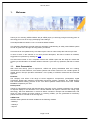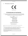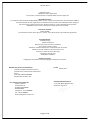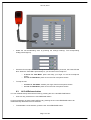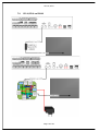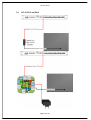
1
CD-16, CD-8 In Wall Microphone Console User Manual User manual, CD-16-8-10UMS01-V01R03 version 01 revision 02 date 14-09-2011 www.ateis-europe.com ATEÏS Europe BV - Sydneystraat 42 - 3047BP ROTTERDAM - NETHERLANDS Phone +31 (0)10 2088690 - Fax +31 (0)10 2088699 P.O. box 12172, 3004 GD, ROTTERDAM - Chamber of commerce: 24465391 Rotterdam Page 1 of 22 DELIVERING Your MESSAGE CD-16, CD-8 CD-16, CD-8 1. Table of Content 1. Table of Content _______________________________________________ 2 1. Welcome: _____________________________________________________ 3 1.1. Ateis Presentation __________________________________________________ 3 1.2. EC Declaration of Conformity ________________________________________ 5 2. CD-16,CD-8 System Presentation _________________________________ 7 3. Hardware Presentation__________________________________________ 8 3.1. Front view ________________________________________________________ 9 3.2. Rear view ________________________________________________________ 10 3.3. External device: Junction Box _______________________________________ 10 4. LED Indicators _______________________________________________ 12 4.1. General system indicators __________________________________________ 12 4.2. Configurable key status LED ________________________________________ 12 4.3. TALK and ALL CALL/RELEASE LEDs ________________________________ 12 5. Working with the VACIE System _________________________________ 12 5.1. Busy zone indication ______________________________________________ 12 5.2. Starting a microphone call __________________________________________ 13 5.3. All Call/Release button _____________________________________________ 14 · 6. Monitoring speaker _________________________________________________ 15 CD-16,CD-8 connections _______________________________________ 15 6.1. RS485 through CAT5 ______________________________________________ 15 6.2. CD-16,CD-8 on DIVA8 ______________________________________________ 16 6.3. CD-16,CD-8 on IDA8 _______________________________________________ 17 6.4. CD-16,CD-8 on IDA4 _______________________________________________ 18 7. CD-16,CD-8 troubleshooting guide _______________________________ 19 7.1. CD-16,CD-8 can’t boot _____________________________________________ 19 7.2. Noise in the speaker _______________________________________________ 19 7.3. CD-16,CD-8 is powered ON but the buttons don’t work. __________________ 19 7.4. CD-16,CD-8 is connected to VACIE but there is a connection fault state ____ 19 8. Safety Declaration ____________________________________________ 20 9. International sales and service points ____________________________ 22 Page 2 of 22 CD-16, CD-8 1. Welcome: Thank you for choosing ATEÏS PSSG2. We (at ATEÏS) hope you will enjoy using this exciting piece of technology as much as we enjoy developing and building it. This Help file Manual version is: Ver: CD-‐16-‐8-‐10UMS01-‐V01R02 This manual is intended to provide users the necessary understanding to safely uses PSSG2 system as well as guide users through all configuration procedures. This manual can be updated at any time without prior notice in order to keep this manual up to date. In case of errors in this manual or not clear process description, feel free to submit us mistakes, suggestions or questions by sending an email. This document intends to be a complete manual and ATEIS hopes that this Help file manual will provide you all information or answers needed. However if you have any questions, feel free to contact us. 1.1. Ateis Presentation With more than twenty years of experience, ATEÏS has quickly established itself as a leading manufacturer of Public Address, Voice Alarm systems and counter intercoms. The constant growth of market share in Europe provides confirmation of the quality of ATEÏS’s commercial and technical approach. Products: The company now offers a full range of sound equipment: microphones, preamplifiers, digital processors, digital audio matrixes, loud-speaker monitoring systems, amplifiers, etc. ATEÏS designs and manufactures leading products in the voice alarm systems market which have been certified EN60849 compliant by the TÜV. Development: Thanks to a development team that includes thirty engineers, and to constant investment, we are able to respond rapidly to the demands of our various markets with specific solutions and cutting edge technology. We have distributors in more than fifteen countries in Europe and the Middle East, with whom we have carried out major projects. In choosing ATEÏS, you are guaranteed a trustworthy partner that can be counted on for the long term. ATEÏS Field: ATEÏS's audio systems have been installed in the following markets: - Railways - Subways - Airports Page 3 of 22 CD-16, CD-8 - High raise buildings - Hotels - Restaurants - Shopping malls - Theme parks - Places of worship - Stadia. - Museums. - Industrial buildings - Industrial plants - Commercial buildings Page 4 of 22 CD-16, CD-8 2. EC Declaration of Conformity 0359-‐CPD-‐0140 EC Declaration of Conformity Penton Communication Incorporated, No. 28-‐2, Ta-‐Ya Road, Ta-‐Ya, Taichung, Taiwan as manufacturer having sole responsibility, hereby declares that the following product versions comply with the applicable provisions of the DIRECTIVES. In case of alterations to the product, not agreed upon and not directed by Penton Communication Incorporated, this declaration is no longer valid. Product: DIVA8 SYSTEM VACIE comprising Models; DIVA8MG2, Master Controller DIVA8SG2, Slave Controller PSS-‐G2, Console device CD8-‐G2, Console device CD16-‐G2, Console device DPAfour125, Power amplifier DPAfour250, Power amplifier SPA-‐2120, Power amplifier SPA-‐2240, Power amplifier Powersonic, PS-‐12750 12V75AH battery, Mounted in the bottom of the enclosure DK7820.XXX Rittal System cabinet* XXX – denotes cabinet size The system cabinet must meet the following minimum requirements where an alternative cabinet is used: • Comply with Class 3k5 of EN 60721-‐3-‐3:1995 as amended by EN 60721-‐3-‐3:1995/A2:1997. • Complies with EN 60297-‐3-‐100 and be constructed with a minimum of 16-‐gauge steel, with a fully welded rack frame with fixed front to back equipment chassis carriers. • Have a transparent lockable front door with a maximum frame size around the transparent window such that it indications are viewable at the limits specified in EN54-‐16: 2008. • Have a minimum IP rating of IP 30 in accordance with EN 60529: 2000, with the front hinged door in both the open and closed position • Removable / hinged panel(s), that are provided to gain access to part of the equipment, other than that detailed above, must use of alternative key or different lockable mechanism to that used for the front door. Page 5 of 22 CD-16, CD-8 Conditions of use: Suitable for indoor applications To be used in conjunction with a compliant EN54-‐4 power supply unit Applicable Directive: In compliance with the Directive 89/106/EEC of the council of European Communities of 21 December 1988 on the approximation of laws, regulations and administrative provisions of the Member States relating to the construction products (Construction Products Directive – CPD), amended by the Directive 93/68/EEC of the Council of European Communities of 22 July 1993. Evaluation standard: EN54-‐16:2008 Fire detection and fire alarm systems – Part 16: Voice Alarm Control and Indicating Equipment Provided Options: -‐ Audible warning -‐ Phased evacuation -‐ Manual reset of the voice alarm condition -‐ Voice alarm condition output -‐ Indication of faults related to the transmission path of the CIE -‐ Indication of faults related to the voice alarm zones -‐ Interface to external control device(s) -‐ Emergency microphones -‐ Redundant amplifiers Ancillary Functions: Background music/audio and zone paging (2-‐simultaneous channels) Notified body (Test and Certification): Intertek Testing & Certification Limited Intertek House, Cleeve Road, Leatherhead, Surrey, KT22 7SB, UNITED KINGDOM Notified Body number: 035 First placed on the market by: ATEÏS Europe BV Sydneystraat 42 3047BP ROTTERDAM NETHERLANDS Telephone: +31 10 2088690 Fax: +31 10 2088699 Email: info@ateis-‐europe.com Issued: March 2012 Page 6 of 22 Authorized Representative: J.H.E. Haak (Managing Director) Authorized signature: CD-16, CD-8 3. CD-16,CD-8 System Presentation Wall-mount heavy duty remote paging console with Access level 2 protection to comply with the EN 54-16. Compatible with DIVA8 System, IDA4 System and IDA8 System and communicates over a dedicated RS485 for Power, audio and DATA. The unit comprises of 16 zones / 16 buttons with fist firemen’s microphone in a metal surface mount wall-box. It provides robust IP-30 protection. Each CD-16,CD-8 contains a PSM-Master PCB with extension keypad and uses the same architecture as for the PSM-series of microphone consoles. Each DIVA8 System, IDA4 System and IDA8 System can handle up to 32 CD-16,CD-8 . CD-8 is limited to eight programmable keys. The buttons can represent a single zone or a group of zones. All buttons can be programmed with drag & drop features from the DIVA8 System, IDA4 System and IDA8 System GUI and the PTT button can be programmed for Push To Talk or for latching functionality. The unit offers “Hold” and “Busy” LED signals in addition to the zone LED’s, and these allow the easy identification of selection / Busy signals for the user. In addition, to comply with EN 54-16, separate POWER, FAULT and EVAC indicators are provided. The RS485 communication protocol offers daisy chaining of up to 300 m on a simple CAT5 cable, and yet makes outlets easy to connect via a standard RJ45 connector. Page 7 of 22 CD-16, CD-8 4. Hardware Presentation General Information: • 16 buttons / Music button 1&2 plus separate PTT button. 8 buttons for CD-8. • Fireman fist microphone with PTT (CB-type). • Distortion less than 0.6%. • Inputs S/N ratio: >75 dBu. • Frequency response: 100 Hz - 16 kHz (For the electronics). • Feedback speaker. • 2 stereo RCA entries with selection buttons. • 3 LED indicators: Power/General Fault/Evacuation active. • Voltage: 24 VDC (Provided by DIVA8 System,IDA4 System and IDA8 System). • Dimensions: 334x247x134 mm. • Colour: RAL 7016. Page 8 of 22 CD-16, CD-8 Front View : 4.1. • • • • • • • • Front view Monitoring Speaker: VACIE audio streams monitoring loudspeaker. General Status LED: o POWER LED: Indicates the power status of the CD-16,CD-8 o FAULT LED: Indicates the presence of a fault on the system the CD-16,CD-8 is linked to. o EVAC LED: Indicates the presence of a evacuation state on the system the CD16,CD-8 is linked to. Zone and Selection LED: o BUSY LED: Indicates the zone busy state. o HOLD LED: Indicates zone selection key active state. Configurable button: Depending on which VACIE system the CD-16,CD-8 is connected to, the programmable key could offer a big variety of function. Reading the VACIE user manuals will let you know all the possibilities offered (IDA4, IDA8 and DIVA8). Door Key Locker: The CD-16,CD-8 door has been designed to offer EN54 level access. This is why a door locker has been provided. Fireman Microphone Input: Allows the connection of the SHM1 microphone. Talk LED: indicates when a call is active. Blinks during chime. All Call/Release Button: Allows instantaneously the selection or release of all zone keys. Page 9 of 22 CD-16, CD-8 4.2. • Rear view RJ45 Connnector: CD-16,CD-8 output to VACIE. This connection is made through shielded CAT5 cable, read the how to connect CD-16,CD-8 to VACIE chapters. 4.3. External device: Junction Box Easy chain-connection of LAP peripherals (URC and PPM) or VACIE peripherals (PSM, CD-16,CD-8) using standard shielded CAT5 cables. KEY FEATURES: • • 5 x RJ45: • Connection to previous JB (or LAP bus on the first JB, Call stations bus on VACIE system) • RS485-SIDE for URC connection • Easy connection to a Master PPM using the supplied 10 pins cable. • Connection to first Slave PPM/PSM (Slave features are not available on PPM and CD-16,CD-8) • MAIN OUT connection to next JB 2 internal screw connectors for 0 dB audio: • audio output from PPM/PSM/CD-16,CD-8 microphone --> Audio Output (not used with PSM/CD-16,CD-8) • audio input to PPM speaker --> Audio Input (Not used with PSM/CD-16,CD-8) Page 10 of 22 CD-16, CD-8 • 1 input for additional 24V power supply. (Depending on distance between LAP and PPM/URC or PSM/CD-16,CD-8 to the VACIE, you will have to put an external power supply) • 1 internal switch for PPM/PSM/CD-16,CD-8 Master or Slave selection. (Slave features are not available PPM and CD-16,CD-8) • 1 internal switch for System or Local power supply selection. Page 11 of 22 CD-16, CD-8 5. LED Indicators The CD-16,CD-8 microphone console offers general VACIE indicators LED as well as configurable button status LED. 5.1. General system indicators The CD-16,CD-8 has three different main LED indicators to show different status of the CD-16,CD-8 and VACIE system: Power, Fault and Evac states. In order to check for the LEDs condition, every 35 seconds both Fault and Evac blinked once. Power LED: indicates the presence of power on the CD-16,CD-8. Fault LED: the fault LED is permanently lit if a fault state in the VACIE system has been engaged. Evac LED: the Evac LED is permanently lit if a evacuation state in the VACIE system has been engaged. 5.2. Configurable key status LED As briefly introduced before, the key configuration of the CD-16,CD-8 depends on the VACIE system used with it. Please refer to VACIE user manuals to learn more about all the configuration possibilities offered. However, independently from the VACIE system, when zone selection key are programmed, the two zone status LED act as follow: BUSY LED: indicates the presence an audio event on the corresponding zone or group of zone. HOLD LED: The HOLD LED indicates the user that the zone is still in an active selection state. When lit, all next call or music routing will be routed to that zone. Note: Before making any call or any music routing, make sure that the HOLD LEDs reflect the desired zones selection. 5.3. TALK and ALL CALL/RELEASE LEDs The CD-16,CD-8 call is activated by the fist microphone switch. The talk LED will reflect the status of the call. ALL CALL/RELEASE LED: Will be lit when a all call zone selection is active or when all individual zone keys have been selected. Will be OFF when the button is used for the release of an all call selection. TALK LED: Will be lit when the user can speak in the microphone and blinking during the broadcasting of a pre or post chime. 6. Working with the VACIE System As stated previously, the key configurations and possibilities depend on the VACIE system connected to the CD-16,CD-8. However some operations are common to all system. 6.1. Busy zone indication When a system zone is occupied by an audio broadcasting, the corresponding CD-16,CD-8 zone key is signalized as busy, the corresponding zone busy LED will lit. Page 12 of 22 CD-16, CD-8 6.2. Starting a microphone call In order to start a call in a zone or group of zone, follow the next steps. Start a call without chime: • • Open the CD-16,CD-8 door. Grab the handheld fireman microphone. • Select the call broadcasting zone by pressing the zone(s) button(s). The corresponding LED(s) should light up. • Press the fist microphone switch. When the Talk LED is permanently lit, you can talk in the microphone. o o • In Press To Talk Mode: press and keep your finger on the fist microphone switch. In Lock To Talk Mode: press once on the Fist microphone switch. To stop the call: o o In Press To Talk Mode: release your finger from fist microphone switch. In Lock To Talk Mode: press once on the Fist microphone switch. Start a call with chime: • • Open the CD-16,CD-8 door. Grab the handheld fireman microphone. Page 13 of 22 CD-16, CD-8 • Select the call broadcasting zone by pressing the zone(s) button(s). The corresponding LED(s) should light up. • Press the fist microphone switch. During the broadcasting of the pre-chime, the TALK LED will blink. When the Talk LED is permanently lit, you can talk in the microphone. o o • In Press To Talk Mode: press and keep your finger on the fist microphone switch. In Lock To Talk Mode: press once on the Fist microphone switch. To stop the call: o o 6.3. In Press To Talk Mode: release your finger from fist microphone switch. In Lock To Talk Mode: press once on the Fist microphone switch. All Call/Release button You can instantaneously select all the zones by pressing the ALL CALL/RELEASE button. • Prior to a call, press the ALL CALL/RELEASE button. If a zone(s) selection is active (HOLD LED are lit), pressing the ALL CALL/RELEASE button will instantaneously deactivate the zone selection. • To deactivate a zone selection, press the ALL CALL/RELEASE button. Page 14 of 22 CD-16, CD-8 • Monitoring speaker The audio that is routed to the CD-16,CD-8 monitoring speaker depends on the VACIE configuration. Please refer to the VACIE user manual to learn more about how to route audio on the CD-16,CD-8 monitoring speaker. The monitoring speaker level can be adjusted trough the VACIE configuration software. 7. CD-16,CD-8 connections In this chapter you will learn how to connect a CD-16,CD-8 microphone to a VACIE system as well as how to connect external microphone, external speaker and telephone handset. 7.1. RS485 through CAT5 The CD-16,CD-8 uses RS485 protocol over shielded CAT5 to transport data from the microphone to the VACIE. The theoretical maximum distance for RS485 is 1000 meters. However, as the CD-16,CD-8 is powered via the VACIE system a maximum of 200 meters is recommended without the use of an external power supply. The CD-16,CD-8 microphone is supplied with a 10 to 8 pins CAT5 cable converter. When using an external power supply, make sure that the Junction Box power switch is set to EXT.PWR. and the MASTER-SLAVE switch to the MASTER position. Page 15 of 22 CD-16, CD-8 7.2. CD-16,CD-8 on DIVA8 Page 16 of 22 CD-16, CD-8 7.3. CD-16,CD-8 on IDA8 Up to 4 CD-16,CD-8 can be connected to an IDA8C or IDA8S. Page 17 of 22 CD-16, CD-8 7.4. CD-16,CD-8 on IDA4 Page 18 of 22 CD-16, CD-8 8. CD-16,CD-8 troubleshooting guide The CD-16,CD-8 microphone is constantly monitored through the VACIE system. Fault indication and messages could vary depending on the VACIE system. For more information about CD-16,CD-8 fault, please read IDA4, IDA8 and DIVA8 user manuals. 8.1. • • • CD-16,CD-8 can’t boot Make sure the CAT5 cable is correctly connected. Make sure the CD-16,CD-8 power LED is lit. If no power or if the PSS still doesn’t boot, please contact your ATEIS dealer. 8.2. Noise in the speaker If digital noise can be heard in the CD-16,CD-8 monitoring speaker: • • • Verify that the CAT5 cable is from the correct type. Verify the CAT5 cable condition. If nothing helps, please contact your ATEIS dealer. 8.3. • • Verify that the CD-16,CD-8 microphone console is activated in the VACIE software configuration. If nothing helps, please contact your ATEIS dealer. 8.4. • • • • CD-16,CD-8 is powered ON but the buttons don’t work. CD-16,CD-8 is connected to VACIE but there is a connection fault state Verify that the CD-16,CD-8 microphone console is activated in the VACIE software configuration. Verify the CAT5 cable condition. Make sure the CAT5 cable is correctly connected. If nothing helps, please contact your ATEIS dealer. Page 19 of 22 CD-16, CD-8 9. Safety Declaration • Do not expose the PSSG2 to extreme temperatures, direct sunlight, humidity, or dust, which could cause fire or electrical shock hazard. • Keep away water or other liquids from the PSSG2. Otherwise fire or electrical shock may result. • In case of using external power supply, connect the PSSG2 only to an 24 VDC outlet of the type stated in this Owner's Manual. Otherwise fire and electrical shock hazard results. • When disconnecting the power cord from an AC outlet always grab the plug. Never pull the cord. A damaged power cord is a potential risk of fire and electrical shock hazard. • Avoid touching power plugs with wet hands. Doing so is a potential electrical shock hazard. • Take care for correct polarity when operating the PSSG2 from a DC power source. Reversed polarity may cause damage to the unit or the batteries. • Avoid placing heavy objects on power cords. A damaged power cord is a fire and electrical shock hazard. • Do not cut, scratch, bend, twist, pull, or heat the power cord. A damaged power cord is a fire and electrical shock hazard. Ask your ATEÏS dealer for replacement. • Turn off immediately the unit, remove the power cord from the AC outlet and consult your ATEÏS dealer in any of the following circumstances: • Smoke, odor, or noise getting out of the unit. • Foreign objects or liquids get inside the PSSG2. • The unit has been dropped or the shell is damaged. • The power cord is damaged. If you continue using the PSSG2, fire and electrical shock may result. • Do not drop or insert metallic objects or flammable materials into the unit as this may result in fire and electrical shock. • Do not remove the PSSG2's cover, as there are exposed parts inside carrying high voltages that may cause an electrical shock. Contact your ATEÏS dealer if internal inspection, maintenance, or repair is necessary. • Do not try to make any modifications to the PSSG2. This is a potential fire and electrical shock hazard. Page 20 of 22 CD-16, CD-8 • To prevent the unit from falling down and causing personal injury and/or property damage, avoid installing or mounting the unit in unstable locations. • Operate the PSSG2 in an environment with a free-air temperature of between 0 °C and 40 °C (32 °F and 104 °F). • Do not use benzene, thinner, or chemicals to clean the PSSG2. Use only a soft, dry cloth. • If the PSSG2 is moved from a cold place (e.g., overnight in a car) to a warmer environment, condensation may form inside the unit, which may affect performance. Allow the PSSG2 to acclimatize for about one hour before use. Page 21 of 22 CD-16, CD-8 10. International sales and service points Page 22 of 22