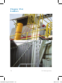
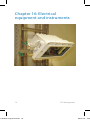
1
Håndbok Beste praksis Forebygging av Fallende Gjenstander Rev 03_Layout
Håndbok
Handbook
BestePRACTICE
praksis
BEST
ForeBygging
av
DROPPES
OBJECT
Fallende gjenstander
MANAGEMENT
S handbok eng 9x15.indd 1
rev. 03-2012
Rev.
03-2012
www.samarbeidforsikkerhet.no
02.07.12 14.2
Foreword
Dropped objects (DO) present significant safety challenges. Surveys have shown that these challenges relate to a number of factors, including work processes, behaviour, design, and the insufficient securing of equipment.
As an improvement measure, Working Together for Safety (SfS)
decided to issue this handbook, which summarises relevant requirements relating to the securing of tools and fixed and moveable equipment.
The handbook was originally produced by Statoil, in close collaboration with equipment suppliers and users. An SfS working
group, with members from both operators and suppliers, has been
responsible for the revisions made to this edition. The purpose of
the handbook is to disseminate knowledge and best practice to the
entire industry – and eliminate dropped objects!
Two fundamental concepts in all HSE work are an understanding
of risk and a barrier-based approach. Risk includes both probability and consequences. The probability that a DO will occur can be
significantly reduced through good design and the establishment
of the barriers described in this handbook. The consequences can
also be reduced through good design and planning: Low-weight
equipment placed at low heights and away from walkways results
in reduced risk through reduced consequences.
SfS would like to thank Statoil for taking the initiative to create
this handbook, and encourages everyone to use it actively in order
to understand and establish the necessary barriers. We would also
like to thank DOM Group AS for their assistance with images and
the layout of this edition.
Equipment suppliers in particular are encouraged to continually
work to find safer solutions.
Hugo Halvorsen
General Manager, SfS
2
S handbok eng 9x15.indd 2
DO Management
02.07.12 14.2
Innhold
FOREWORD .................................................................................. 2
THE PURPOSE OF THIS HANDBOOK....................................... 6
ABBREVIATIONS / TERMS.......................................................... 8
PART 1: GENERAL INFORMATION........................................... 11
CHAPTER 1: THE MOST IMPORTANT AREAS
– WHERE DO DROPPED OBJECTS OCCUR?..... 11
CHAPTER 2: BARRIERS............................................................... 12
CHAPTER 3: FALL ENERGY AND FALL FACTORS................. 14
CHAPTER 4: ROUTINES FOR WORK AT HEIGHT................... 16
CHAPTER 5: SECURING TOOLS AND EQUIPMENT
DURING WORK AT HEIGHT................................ 5.1: Securing tools <5 kg.......................................... 5.2: Securing tools 5-25 kg....................................... 5.3: Securing other portable equipment.................... 5.4: Securing equipment and parts........................... 5.5: Tool cabinets for work at height........................ 17
18
20
22
24
26
CHAPTER 6: SECURING PERSONNEL...................................... 28
CHAPTER 7: SECURING TOOLS AND EQUIPMENT
AGAINST WIND AND WEATHER
CONDITIONS.......................................................... 30
CHAPTER 8: UNNECESSARY EQUIPMENT AT HEIGHT........ 32
CHAPTER 9: POST INSPECTION /
FINAL CHECK OF THE WORK SITE................... 34
CHAPTER 10: OBSERVATION TECHNIQUE............................... 36
CHAPTER 11: RESPONSIBILITY AND FOLLOW-UP................. 37
CHAPTER 12: GALVANIC CORROSION...................................... 38
DO Management
S handbok eng 9x15.indd 3
3
02.07.12 14.2
PART 2: SECURING FIXED EQUIPMENT................................. 40
CHAPTER 13: BOLTED CONNECTIONS...................................... 13.1: Nord-Lock bolt securing system..................... 13.2: Spiralock.......................................................... 13.3: Castle nuts with cotter pins.............................. 13.4: Nyloc lock nuts................................................ 13.5: All-metal lock nuts.......................................... 13.6: Tab washers / Tab plates.................................. 13.7: Palnut............................................................... 13.8: Lock-wiring..................................................... 13.9: Special bolts..................................................... 41
42
42
44
44
46
46
48
48
50
CHAPTER 14: SECURING DEVICES............................................ 14.1: Correct use of cotter pins................................. 14.2: Securing pins / safety pins............................... 14.3: Wire, chains and couplings.............................. 14.4: Correct installation of wire clamps.................. 52
53
54
56
58
CHAPTER 15: STRUCTURE........................................................... 15.1: Grating............................................................. 15.2: Piping and equipment feedthroughs................ 15.3: Railings............................................................ 15.4: Toe boards........................................................ 15.5: Swing gates...................................................... 15.6: Ladders............................................................ 15.7: Wind walls....................................................... 60
61
62
64
66
68
70
72
CHAPTER 16: ELECTRICAL EQUIPMENT
AND INSTRUMENTS............................................. 16.1: Floodlights....................................................... 16.2: Lighting fixtures.............................................. 16.3: Navigation lights / lanterns.............................. 74
75
76
78
4
S handbok eng 9x15.indd 4
DO Management
02.07.12 14.2
16.4: CCTV cameras................................................ 16.5: Crane boom camera and floodlight.................. 16.6: Loudspeakers................................................... 16.7: Junction boxes and cabinets............................ 16.8: Cable trays and cable ladders.......................... 16.9: Antennas, windsocks and sensors.................... 80
84
86
88
90
92
CHAPTER 17: OTHER EQUIPMENT............................................. 94
17.1: Valve handles and valve wheels...................... 95
17.2: Chain-operated valves..................................... 96
17.3: Locks on insulation cladding........................... 98
17.4: Storage and placement of gas cylinders.......... 100
17.5: Snatch blocks................................................... 102
17.6: Umbilical roller sheaves (Banana sheaves)..... 104
17.7: Loop hoses....................................................... 106
17.8: Signs................................................................ 108
17.9: Racks and storage............................................ 110
17.10: Derrick evacuation equipment....................... 112
RELEVANT REFERENCES........................................................... 114
DO Management
S handbok eng 9x15.indd 5
5
02.07.12 14.2
The purpose of this handbook
This handbook is intended to help eliminate the risk of dropped
objects. It applies to equipment that shall be procured, as well as to
equipment that is already in use. Best practices have been prepared
for the equipment covered in this document, which in many cases
set a new standard for our activities. An important goal has been to
define barriers that shall prevent dropped objects, and which shall
be used in the procurement, use and maintenance of equipment.
When procuring new equipment, we must endeavour to use integrated solutions/barriers, since this is the basis for eliminating
dropped objects. This means that both suppliers and buyers must
be aware of this problem.
When installing new equipment, an evaluation of the risks relating
to placement must be carried out in order to reduce the danger of
collisions/DO. In addition, equipment must be designed to tolerate
the environment for which it is intended, and installed to provide
the safest possible access for maintenance (ref. NORSOK, PSA,
OLF and the Norwegian Labour Inspection Authority).
The best practices described in this handbook must be complied
with throughout the entire value chain, from design to removal.
By following best practices, we will move towards achieving our
overall goal of 0 dropped objects.
For lifting operations, the packing and securing of loads, and the
use and inspection of load containers, please refer to OLF guidelines 116 and NORSOK R-003 / R-005.
Who is responsible? Everyone in the value chain! (See next page)
6
S handbok eng 9x15.indd 6
DO Management
02.07.12 14.2
DO Management
S handbok eng 9x15.indd 7
7
02.07.12 14.2
Abbreviations / terms
ABS: American Bureau of Shipping
AD: Arbeidsdepartementet (The Norwegian Ministry of Labour)
AISI:American Iron and Steel Institute
API: American Petroleum Institute, issues production standards
for equipment used in the oil industry.
Atil: Arbeidstilsynet (The Norwegian Labour Inspection Authority)
Barrier, primary: A barrier that is established through installing
equipment in accordance with a standard procedure or through
bolts being installed with sufficient torque/pretension.
Barrier, secondary (secondary retention): A barrier that is established in order to achieve an extra level of safety (e.g. safety wire,
the locking of bolt connections in order to avoid loss of torque and
pretension), and to protect and secure equipment and personnel.
CCTV: (Closed-circuit television) surveillance camera
Competent person: A person that can document practical and theoretical knowledge within a particular area or discipline.
DIBt: Deutsches Institut für Bautechnik
DnV: Det Norske Veritas
Documentable: Equipment must be labelled in a way that ensures
traceability to the producer or importer, and with information including the load, area of application and product standard.
Documented training: Training through which it can be documented that the person who shall use the equipment has received
practical and theoretical training that provides knowledge about
the equipment’s assembly, operation, utilisation and areas of application, as well as maintenance and control in accordance with
the requirements that are set for the safe use and operation of the
equipment in regulations and user guides.
8
S handbok eng 9x15.indd 8
DO Management
02.07.12 14.2
DO: Dropped object, i.e. the uncontrolled movement of an object
from one level to another. It is emphasised that dropped objects do
not only occur during work at heights.
DROPS: Dropped Object Prevention Scheme, a global industry
initiative that focuses on the prevention of dropped objects (www.
dropsonline.org).
EN: European Standards, issued by CEN (The European Committee for Standardisation) and adopted by one of the three recognised
European standardisation bodies – CEN, CENELEC or ETSI.
F.E.M: European Federation of Material Handling
HSE: Health, safety and environment
ISO: International Organisation for Standardisation
Lifting equipment: Common term for lifting gear, lifting devices
and lifting units, used in combination or individually.
NHD: Nærings- og Handelsdepartementet (The Norwegian Ministry of Trade and Industry)
OLF: Oljeindustriens landsforening (The Norwegian Oil Industry
Association)
PSA: The Petroleum Safety Authority
Risk: An expression of the danger that an undesirable incident
represents to people, the environment or material assets. The risk
expresses the probability of an accident occurring, as well as its
consequences.
Risk evaluation: A systematic method of describing and/or calculating the risk to people, the environment and equipment. A risk
analysis is carried out through the mapping of undesirable incidents and their causes and consequences.
RNNP: Risikonivå i Norsk Petroleumsvirksomhet (Trends in risk
levels in the Norwegian petroleum industry)
DO Management
S handbok eng 9x15.indd 9
9
02.07.12 14.2
SfS: Samarbeid for Sikkerhet (“Working Together for Safety”)
is among the most extensive collaborative projects within the field
of health, safety and the environment (HSE) within the oil and gas
industry.
SWL:Safe working load
TÜV:Technischer Überwachungsverein
Weak Link: A Weak Link is intended to be the weakest connection
point between a tool and its user. The user is able to disconnect
from the tool with a strong tug should an emergency situation occur. Weak Link 1 kg is designed to withstand a tug of 10 Joules
without deformation, Weak Link 2 kg is designed to withstand a
tug of 20 Joules without deformation, etc.
Work at height: All work carried out at a height of 2 m or more
above a fixed deck. Remember that on a rig installation, work at
height can be carried out on all decks. Be aware of vessels and
subsea equipment.
WLL: Work load limit
Shall/must and should:
In this handbook, the word “must” or “shall” is used where we
believe that authority requirements apply.
The word “should” refers to a best practice. If another solution is
selected, an equal or better level of safety must be documented.
10
S handbok eng 9x15.indd 10
DO Management
02.07.12 14.2
Part 1: General information
Chapter 1: The most
important areas – where do
dropped objects occur?
The PSA’s project ‘Trends in risk levels in the Norwegian petroleum industry’ (RNNP), publishes an annual report which looks at
the level of risk within the petroleum industry. One of the surveyed
indicators is dropped objects, DFU 21.
During the period 2002-2010, an average of 235 incidents relating
to dropped objects were reported to RNNP each year. The number
of incidents reported each year has remained relatively stable,
with a slight decrease during the last three years, to 146 incidents
in 2010. On the Norwegian continental shelf, two deaths and 85
personal injuries relating to dropped objects have occurred since
2002.
According to RNNP, approximately half of all dropped objects incidents that occurred in recent years were related either to ‘drilling
and wells’ or ‘cranes and lifting’ related work. Of the 873 analysed
DO incidents that occurred between 2006-2010, 27% were related
to design/technical solutions, 44% to human factors, and the remaining 29% were due to external conditions such as the weather,
wind, waves, etc. For more detailed information, please see the
annual RNNP report.
These facts clearly show that DO is an area upon which we
should maintain continual focus in order to reduce the level of
risk within the industry.
DO Management
S handbok eng 9x15.indd 11
11
02.07.12 14.2
Håndbok Beste praksis Forebygging av Fallende Gjenstander Rev 03_Layout
Chapter 2:
kap.2: Barrierer
Barriers
Barriers are
andog
measures
thatskal
shallhindre
preventeller
or reduce
the
Barrierer
erfunctions
funksjoner
tiltak som
redusere
consequences
incidents.
konsekvenseneofavundesirable
uønskede hendelser.
We
have
main types
of barriers:
Vi har
trethree
hovedtyper
barrierer:
Human,
technical
and organisational.
Menneskelige,
Tekniske
og Organisatoriske.
Examples
areFelles
givenfor
below.
Common
to
Eksemplerof
påthese
slike types
finnerofdubarriers
nedenfor.
alle er
at de ikke
all
is that they
not jobbing,
obstruct men
effective
processes,
skalbarriers
være hindringer
forshall
effektiv
ekstrawork
sikkerhetsnett.
but provide an extra safety net.
12
12
S handbok eng 9x15.indd 12
Forebygging
av Fg
DO Management
02.07.12 14.2
v 03_Layout 1
HTO
-
Human
(knowledge, experience, qualities and operational methods)
-
Technical solutions
(safety wires, Nord-Lock, cotter pins, tool bags, etc.) alone can
serve as barrier functions, but they often need to be combined
with organisational and/or human solutions
-
Organisational
(procedures, specifications, checklists, etc.)
H and O solutions cannot fulfil barrier functions alone; they must
always be combined with at least one of the other solutions.
This handbook mainly describes technical barriers.
DO Management
S handbok eng 9x15.indd 13
13
02.07.12 14.2
Chapter 3:
Fall energy and fall factors
Fall factors
The “fall factor”
describes the severity of a fall. It is an
expression of the relationship between
the length of the
fall and the length
of rope available to
break the fall.
The fall factor is
calculated
using
the formula on next
page
Fall energy
All equipment at height has a potential fall energy, which is dependent upon the equipment’s weight and the height from which
it may fall.
14
S handbok eng 9x15.indd 14
DO Management
02.07.12 14.2
Fall energy (Ef) is measured in Joules, and calculated using the
formula Ef=mgh, where m = the weight of the object in kg, h = the
height from which the object is dropped, and g = the gravitational
acceleration (9.81m/s2).
The figure to the left is based on this formula, and can be used to
calculate fall energy to estimate the severity of possible injuries.
The potential for injury depends upon a number of factors, including the equipment’s fall energy, hardness and shape, where it hits
the body, etc.
A fall energy over 40 Joules (red area) may result in serious injury
or death.
A fall energy between 20 and 40 Joules (yellow area) may result in
the need for medical treatment.
A fall energy between 0 and 20 Joules (green area) may result in
the need for first aid, or no injury.
The injury potential must be classified in accordance with these
values, and if necessary adjusted with regard to the type of dropped
object. Sharp objects with low kinetic energy can have a higher injury potential than a blunt/soft object with a higher kinetic energy.
The limits described above are the norms used in the Norwegian petroleum industry. SfS is aware that other forums, such as
DROPS, operate with other limit values.
Fall factor
The fall factor is the length of the fall divided by the length of the
securing device that absorbs the fall energy. The force to which a
person or object is exposed depends on the energy-absorbing properties of the securing device (ability to lengthen without breaking). Energy absorbers are therefore important, even on securing
devices for tools.
When securing persons against falling, the fall factor must preferably be kept below factor 1, and shall under no circumstances
exceed factor 2.
DO Management
S handbok eng 9x15.indd 15
15
02.07.12 14.2
Chapter 4:
Routines for work at height
Work operations within the oil industry often involve work at
height. Many operations therefore contain an element of risk due
to height:
• You are exposed to equipment or work operations above you
• Personnel below you are exposed to your work
• You work at height above a deck
We distinguish between the securing of personnel working at
height, the securing of permanent equipment, and the securing of
tools and parts that are used at height during a work operation.
Ideally, all work should be carried out on a deck with its ends and
openings secured against falls to a lower level. In this situation, the
executing worker is secured against falls, and other personnel are
protected from dropped objects.
However, many operations must be executed at height. For such
operations, approved scaffolding together with secured tools/
equipment and access control will provide the desired level of safety. If it is most appropriate to work from ladders, riding belts or
climbing equipment, the executing worker must also be actively
secured, and a rescue plan must be in place.
Checklist
• Select appropriate equipment
• Only use approved materials (approved scaffolding)
• Do not start work before you have checked that the equipment
is in accordance with regulations
• Ensure that access to the area is restricted if necessary
• Use fall protection equipment if necessary (documented theoretical and practical training is a prerequisite)
• Secure equipment and tools
16
S handbok eng 9x15.indd 16
DO Management
02.07.12 14.2
Håndbok Beste praksis Forebygging av Fallende Gjenstander Rev 03_Layout
Chapter 5:
Securing
toolsavand
equipment
kap.5: sikring
verktøy
og
during
work
at
height
utstyr ved arbeid i høyden
When using tools at height, the potential for dropped objects is
Potensialet
for fallende
gjenstander
ved bruk av verktøy i høyden
great, and represents
a significant
risk.
er stort og utgjør en betydelig risiko.
DO Management
Forebygging av Fg
S handbok eng 9x15.indd 17
17
17
02.07.12 14.2
Chapter 5.1: Securing tools <5 kg
18
S handbok eng 9x15.indd 18
DO Management
02.07.12 14.2
Best practice
• All use of tools at height must be risk assessed
• All tools shall be secured against being dropped, both during
transport/moving and during work
• Attachment points/devices on tools and bags must be documentable
• Fastenings on tools shall be energy-absorbing (energy absorbers)
• A weak link shall be installed between the body and safety wire
when fall arrest devices are used. Weak links for tools weighing over 2 kg should not be used
• Tools heavier than 2 kg should not be secured to the body with
wire. If a coiled cord is used, the limit is 3.5 kg
• A tool bag with internal loops should be used when several
and/or heavy tools are used at height
• Wrist straps can be used for one tool weighing under 1 kg, with
a weak link
• If an attachment point other than the belt or bag is required,
use an appropriate part of the surrounding structure, preferably
above the work level
• For work on/near rotating machines or moving equipment,
tools should normally be secured to the adjacent structure
• Tools used at height should be checked out/in (ref. Tool cabinets for work at height) to ensure that nothing is left behind
DO Management
S handbok eng 9x15.indd 19
19
02.07.12 14.2
Kap.5.2: Sikring av verktøy >5 kg
Chapter 5.2: Securing tools 5-25 kg
20
Forebygging av Fg
20
DO Management
S handbok eng 9x15.indd 20
02.07.12 14.2
Best practice
• All use of heavy tools and hand-held machinery where equipment may fall to an underlying level must be risk assessed
• All heavy tools and hand-held machinery used at height must
be secured against being dropped, both when in use and while
being transported
• Only certified lifting equipment shall be used as securing devices
• The attachment points/devices on tools shall be documented
• Fastenings on tools shall be energy-absorbing (energy absorbers)
• Securing points for tools and machinery must be in place above
the work site, attached to the surrounding structure, not to scaffolding. The securing device must be as taut as possible
• Tools used at height should be checked out/in (ref. Tool cabinets for work at height) to ensure that nothing is left behind
DO Management
S handbok eng 9x15.indd 21
21
02.07.12 14.2
Chapter 5.3:
Kap.5.3: Sikring av annet bærbart utstyr
Securing other portable equipment
22
Forebygging av Fg
22
DO Management
S handbok eng 9x15.indd 22
02.07.12 14.2
Best practice
• All portable equipment used where there is a risk of the equipment falling to an underlying level must be secured against
being dropped
• Carrying pouches must always be used for radios and any other
portable equipment without certified securing points
• Locks on pouches must have a double securing mechanism to
prevent unintentional opening
• Belt clips that allow equipment to become detached when
turned 180º should not be used
• Belts with snap fasteners are not suitable for securing equipment at height
DO Management
S handbok eng 9x15.indd 23
23
02.07.12 14.2
Chapter
5.4: av utstyr og deler
Kap.5.4: Sikring
Securing equipment and parts
24
Forebygging av Fg
24
DO Management
S handbok eng 9x15.indd 24
02.07.12 14.2
Best practice
• All repairs and maintenance work carried out at height must be
risk assessed
• All parts, equipment and materials that are worked with at
height must be secured against being dropped
• Smaller parts must be stored in suitable storage boxes, bags,
etc.
• In restricted areas, such as the derrick, flare boom and cranes,
tools used at height must be logged out and in to ensure that
nothing is left behind
• When the work is finished, a final check and inventory count
must be carried out to ensure that no tools, equipment or materials are left behind at height
DO Management
S handbok eng 9x15.indd 25
25
02.07.12 14.2
Håndbok Beste praksis Forebygging av Fallende Gjenstander Rev 03_Layout
Chapter 5.5:
Tool
cabinets for work at height
Kap.5.5: Høydeskap
26
26
S handbok eng 9x15.indd 26
Forebygging
av Fg
DO Management
02.07.12 14.2
Best practice
• Each cabinet/locker shall be equipped with a list of contents
and be kept locked
• A designated person must be responsible for the cabinet to ensure that all tools taken from and returned to the cabinet are
logged out/in
• The contents of the tool cabinet for work at height and its accompanying log book must be checked at the end of every shift
in which the tools have been used
• All tools must be adequately equipped for securing at height
and must have documented attachment points in accordance
with Chapter 14: Securing devices
• In addition to the necessary tools, cabinets should be equipped
with a sufficient number of:
o Correctly dimensioned safety wires with approved
swage locks
o Locking connectors/snap hooks
o Tool bags with internal fastening devices
o Special belts for fastening of tools and bags
o Weak links for fastening between the body and
safety wire
DO Management
S handbok eng 9x15.indd 27
27
02.07.12 14.2
Chapter 6: Securing personnel
Documented training is a mandatory requirement for all personnel
using fall arrests.
28
S handbok eng 9x15.indd 28
DO Management
02.07.12 14.2
Best practice
• The established control procedures, both before and after use,
must be followed
• Nobody shall work alone or unattended when using fall protection equipment
• Personnel who use fall protection equipment must have documented training that includes rescue methods
• Necessary rescue equipment must always be available at the
work site
• A buddy check of the rigging and equipment must be carried
out
• Fall protection equipment must be CE marked
• The equipment must be checked at least every 12 months by
a competent person and shall be labelled with the date for the
next inspection
• The type of securing equipment shall be selected following an
evaluation of the work site
• The anchor point for suspension shall be able to support at least
10kN (see requirement in NS-EN795)
• The harness should be equipped with a safety strap (e.g. the
SALA trauma strap, which allows you to rest on your feet after
a fall, in order to ensure blood circulation to the legs)
DO Management
S handbok eng 9x15.indd 29
29
02.07.12 14.2
Håndbok Beste praksis Forebygging av Fallende Gjenstander Rev 03_Layout
Chapter 7: Securing tools and
equipment
wind and
kap.7: vind- against
og værsikring
weather conditions
30
30
S handbok eng 9x15.indd 30
DO Management
Forebygging av Fg
02.07.12 14.2
Best practice
• Structures and equipment should be designed so that water
cannot collect and form ice
• Establish routines for inspection before, during and after adverse weather conditions, such as strong winds, high waves,
and the risk of ice/falling ice
• Use available time during shift changes to carry out an extra
check of equipment that may loosen
• Check whether the workplace is clean and tidy. Equipment
stored on deck and in other areas may be blown over by the
wind, so check the securing devices
• Check windsocks, wind meters, floodlights, antennas, antenna
masts and scaffolding
• Carefully check that equipment in the vicinity of the helideck
is sufficiently secured
• Check for any loose objects on roofs, load carriers and in all
storage areas
• Check that the lids of storage boxes are secured
The Area Responsible has a particular responsibility for orderliness and tidiness in his/her area.
DO Management
S handbok eng 9x15.indd 31
31
02.07.12 14.2
kap.8: Unødvendig
utstyr
Chapter
8: Unnecessary
i høyden at height
equipment
32
Forebygging av Fg
32
DO Management
S handbok eng 9x15.indd 32
02.07.12 14.2
Best practice
• Regularly carry out a risk assessment and review of what
equipment is required at height, and what should be removed
• The review should establish whether equipment should be relocated to reduce the risk of collision with mobile equipment
• Inspection and maintenance procedures should be revised regularly, to ensure inspection and maintenance of all equipment
installed at height
• Always carry out a final check to ensure that no equipment or
materials are left behind at height
DO Management
S handbok eng 9x15.indd 33
33
02.07.12 14.2
kap.9: etter
/ sluttkontroll
Chapter
9: Post
inspection /
av arbeidssted
final
check of the work site
34
Forebygging av Fg
34
DO Management
S handbok eng 9x15.indd 34
02.07.12 14.2
Experience shows that a clean and tidy workplace is less exposed
to risk than the opposite.
On facilities and installations with rotations and shift work, this
effect is intensified by the fact that we are also exposed to other
people’s “clutter”.
It is therefore extremely important that we have good routines for
final checks of the work site.
Best practice
• Always keep your work site tidy
• Tools, equipment and materials must be secured in a safe location at the end of each shift
• When the work is finished, a final check and inventory count
must be carried out to ensure that no tools, equipment or materials are left behind at height
• Check that all equipment is installed, secured and returned to
normal operation
• The work site must be left in a clean and tidy state, and all
tools, equipment and materials must be returned to their designated storage place
• Loose objects at height must be removed, attached or secured
• On mobile units, a risk assessment must be carried out to determine whether equipment on work benches shall also be secured
DO Management
S handbok eng 9x15.indd 35
35
02.07.12 14.2
Chapter 10:
Observation technique
Inspection, identification and the categorisation of findings are
the first steps in minimising the potential for dropped objects.
Best practice (inspections)
•
Set aside ample time
•
Limit the size of the area
•
Concentrate on a small number of categories and inspect the area in a structured way in order to maintain an overview
• Limit the number of personnel in each area, in order to maintain an overview
• Findings that do not conform to the established standard or
checklist should be photographed and given an accurate description and site reference
• Follow-up and the correction of findings are decisive factors in
preventing dropped objects
36
S handbok eng 9x15.indd 36
DO Management
02.07.12 14.2
Chapter 11:
Responsibility and follow-up
Best practice
The management’s responsibility
• Ensure a high standard of orderliness and cleanliness, undertake random checks – involve the Area Responsible
• Ensure that routines/systems to prevent dropped objects are
established:
o Active use of image-based inspection programme
o Training in DO observation technique (on the job training)
o Strengthen daily risk management, identify and manage
DO risk
o Learning and transfer of experience
• Ensure that time and resources are set aside for work with these
routines/systems
• Check that the routines/systems are followed/used
Your responsibility
• Follow established routines/systems for the prevention of DO
– follow-up your own actions
• Continually identify potential DO risks
• Eliminate dangers to yourself and others
• Report findings or undesirable incidents
DO Management
S handbok eng 9x15.indd 37
37
02.07.12 14.2
Chapter 12: Galvanic corrosion
Anode (less noble)
Cathode (more noble)
Electrochemical series
Cathode (protected) more noble
–––––––––––––––––––––––––––––––––––––––––––
Graphite
–––––––––––––––––––––––––––––––––––––––––––
Titanium
–––––––––––––––––––––––––––––––––––––––––––
Silver
–––––––––––––––––––––––––––––––––––––––––––
Acid-proof steel A4 – passive
–––––––––––––––––––––––––––––––––––––––––––
Stainless steel A2 – passive
–––––––––––––––––––––––––––––––––––––––––––
Iconel – passive
–––––––––––––––––––––––––––––––––––––––––––
Nickel – passive
–––––––––––––––––––––––––––––––––––––––––––
Silver solder
–––––––––––––––––––––––––––––––––––––––––––
Monel
–––––––––––––––––––––––––––––––––––––––––––
Copper/nickel alloys
–––––––––––––––––––––––––––––––––––––––––––
Bronze
–––––––––––––––––––––––––––––––––––––––––––
Copper
–––––––––––––––––––––––––––––––––––––––––––
Brass
–––––––––––––––––––––––––––––––––––––––––––
Tin
–––––––––––––––––––––––––––––––––––––––––––
Lead
–––––––––––––––––––––––––––––––––––––––––––
Tin solder
–––––––––––––––––––––––––––––––––––––––––––
Cast steel
–––––––––––––––––––––––––––––––––––––––––––
Steel and iron
–––––––––––––––––––––––––––––––––––––––––––
Aluminium 2024 – T4
–––––––––––––––––––––––––––––––––––––––––––
Cadmium
–––––––––––––––––––––––––––––––––––––––––––
Aluminium 1100
–––––––––––––––––––––––––––––––––––––––––––
Galvanised steel
–––––––––––––––––––––––––––––––––––––––––––
Zinc
–––––––––––––––––––––––––––––––––––––––––––
Magnesium alloys
–––––––––––––––––––––––––––––––––––––––––––
Magnesium
–––––––––––––––––––––––––––––––––––––––––––
Anode (corrodes) less noble
As a general rule, only metals of the same or almost the same
nobility should be combined in a corrosive environment.
38
S handbok eng 9x15.indd 38
DO Management
02.07.12 14.2
Galvanic corrosion occurs when two dissimilar metals with different voltage potentials come into contact with each other in the
presence of an electrolyte (damp film or seawater/fresh water).
When this happens, the less noble metal becomes the anode and
the more noble metal becomes the cathode.
If a steel screw is fixed to a copper plate, the screw will be the anode since copper is the more noble metal. The screw will corrode
rapidly as the difference in potential is great.
If the same steel screw is fixed to a less noble plate, e.g. a zinc
plate, the screw will be the cathode, and will therefore not rust. The
zinc plate will corrode, as it is less noble than the screw.
For these reasons, it is important that all securing devices are of the
stainless steel type. This applies to cotter pins, safety pins, securing
wire, and locking wire for threading through nuts and bolts, etc.
DO Management
S handbok eng 9x15.indd 39
39
02.07.12 14.2
Part2:
2:sikring av fastmontert
del
Securing fixed equipment
utstyr
40
Forebygging av Fg
40
DO Management
S handbok eng 9x15.indd 40
02.07.12 14.2
Chapter 13:
Bolted connections
Bolts are currently produced to at least 85 different industrial
standards, and the requirements for bolted connections vary for the
different sectors depending on the given design and requirements
for operation and maintenance.
Achieving a stable bolted connection therefore requires a qualified
evaluation of the following factors:
• Load design
• Choice of materials with respect to mechanical properties and
corrosion resistance
• The use of lubricant, where appropriate
• Pre-tensioning and use of the correct torque equipment
The locking of bolts in order to secure against loss of torque and
pre-tension is defined as secondary retention.
Reasons why so many bolts and bolted connections fail:
• Improper use, installation and handling of the bolt
• Vibrations
• Knocks
• Loads (beyond design)
• Wear
• Corrosion
(30%)
(20%)
(12%)
(11%)
(6%)
(5%)
Source: PSA, 2008
DO Management
S handbok eng 9x15.indd 41
41
02.07.12 14.2
Several independent tests show that double nuts and so-called
counter nuts are not a reliable method for securing screws/bolted
connections. Below are some recommended methods.
42
S handbok eng 9x15.indd 42
DO Management
02.07.12 14.2
Chapter 13.1:
Nord-Lock bolt securing system
Nord-Lock secures the bolted connection using tension instead of
friction. The system consists of a pair of washers that fit together,
with cams on one side and radial teeth on the other. Since the cam
angle ‘ ’ is larger than the thread pitch ‘ß’, a wedge effect is created by the cams, and this prevents the bolt from rotating.
Nord-Lock’s locking washers are certified by several independent
institutes, such as ABS, DIBt, DnV and TÜV.
Each pair of washers has a unique control number, which ensures
full traceability right down to the first installation.
Areas of use:
Almost unlimited, but particularly suitable for connections exposed to vibrations or other dynamic loads. Nord-Lock’s washers
are available in dimensions from 3 mm up to 130 mm in various
materials.
Chapter 13.2:
Spiralock
Spiralock is an all-metal lock nut/bolt with a specially designed
threaded profile that locks when tightened and distributes the tension across the entire length of the thread. This provides better load
distribution, which helps to improve the locking of the bolt connection.
Areas of use:
Most often used in cable tray systems, but can also be used in other
installations.
DO Management
S handbok eng 9x15.indd 43
43
02.07.12 14.2
TANGENT TO PIN
60d
MAXIMUM COTTER
PIN LENGTH
60d
MINIMUM COTTER
PIN LENGTH
A. CASTELLATED NUT ON BOLT
PREFERRED METHOD.
B. CASTELLATED NUT ON BOLT ALTERNATE METHOD.
C. PIN APPLICATION.
00111348
Korrekt
av
Correctmontering
installation
splittpinne
i bolter
of
cotter pins
in bolts
Nyloclåsemuttere
lock nuts
Nyloc
44
Forebygging av Fg
44
DO Management
S handbok eng 9x15.indd 44
02.07.12 14.2
Chapter 13.3:
Castle nuts with cotter pins
Adopted from the aviation industry, castle nuts provide a visual
and reliable method of locking bolted connections. The nut has
radial slots and is locked by non-corrosive cotter pins that are inserted through a hole in the bolt.
Areas of use:
Unlimited, but frequently used for critical bolted connections.
Chapter 13.4:
Nyloc lock nuts
Nyloc lock nuts are used extensively throughout the industry. Nyloc lock nuts should only be used once. Standard Nyloc nuts have
a temperature rating from ÷70°C to +120°C.
Areas of use:
This type of nut is often used for locking in connections where a
certain degree of lost pre-tension can be accepted.
DO Management
S handbok eng 9x15.indd 45
45
02.07.12 14.2
Låsemutter med
Lock nut
splittet topp
with split top
Låsemutter
Lockmed
nut
withdeformert
deformedtopp
top
Låseblikk
Tab washer
Tab
washer
Låseplate
46
Forebygging av Fg
46
DO Management
S handbok eng 9x15.indd 46
02.07.12 14.2
Chapter 13.5:
All-metal lock nuts
All-metal lock nuts can be used on all bolt dimensions. The nut
locks by the threaded section or top of the nut deforming/splitting,
or through the nut having a toothed ring under the collar. This provides greater friction between the bolt/underlay and nut, providing
a secure connection. There are many varieties and suppliers on the
market.
Areas of use:
These nuts have an almost unlimited application.
Chapter 13.6:
Tab washers / Tab plates
Tab washers can be used on all dimensions and in any application
where the use of tab washers is appropriate. There are several types
with different areas of application for locking either nuts or bolts.
It is important to use the correct type for each purpose.
Areas of use:
Typically used on machinery where it is important to prevent the
bolt from rotating.
DO Management
S handbok eng 9x15.indd 47
47
02.07.12 14.2
PALNUT
PALNUTDIN
DIN7967
7967Låsemutter
Lock nut
Sying av bolter
Lock-wiring bolts
48
Forebygging av Fg
48
DO Management
S handbok eng 9x15.indd 48
02.07.12 14.2
Chapter 13.7:
Palnut
Palnut lock nuts have been on the market for several decades as
an alternative for locking bolted connections. The Palnut locks by
“cutting” itself into the threads on the bolt when it is tightened. In
an offshore context, Palnut lock nuts are usually used for locking
above standard nuts.
Areas of use:
On through-bolts in fixed equipment and drilling equipment. Easy
to install where secondary retention is not in place.
Chapter 13.8:
Lock-wiring
The lock-wiring of bolts is a locking method adopted from the
aviation industry. In brief, the method involves threading a special
stainless wire through a hole in the bolt head, which is twisted and
locked to the next bolt or structure, thus preventing the bolt from
rotating and loosening. The wire can be used to lock a maximum
of three bolts in a row, as shown in the illustration (for information about the size of the hole in the bolt head, see EN-ISO 7378).
Areas of use:
Used extensively for locking external bolted connections on drilling and pipe-handling equipment. Often used where there are no
through-bolts and/or it is necessary to be able to easily check the
locking visually.
DO Management
S handbok eng 9x15.indd 49
49
02.07.12 14.2
Chapter 13.9:
Special bolts
BONDURA BOLT
Bondura bolts have a construction that can take up movement
and ovality through the use of expanding tapered sleeves at both
ends of the bolt. There are several variants of the bolt, including
straight-through versions and others that are fitted from one side.
Standard screws are tightened to press in the cones. The bolt is
fixed directly to the machine or equipment with locking screws.
This prevents the bolt from loosening, falling out or rotating in
the bolt hole.
Bondura bolts must be fitted and maintained in accordance with
the manufacturer’s specifications. Bondura bolts are certified in accordance with API 8C and F.E.M. regulations.
Areas of use:
For example, as a replacement for clevis bolts in top drives, and
hinge bolts on dollies, pipe handling equipment and cranes.
50
S handbok eng 9x15.indd 50
DO Management
02.07.12 14.2
SUPERBOLT®
SUPERBOLT® Multi-Jackbolt
Multi-Jackbolt Tensioners
Tensioners MJT
MJT
SUPERBOLT®
både som
eller
som
The SUPERBOLTMJT-finnes
® MJT is supplied
as a mutter
nut or bolt
thatbolt
replaces
erstatning
for bolting
konvensjonelle
conventional
elements.bolte-elementer.
De
er are
enkle
og trygge
å bruke
fordi
er nødvendig
They
simple
and safe
to use,
askun
onlyhåndverktøy
hand tools are
necessary
for
Bruk
stramme
utstyr
eller
for installasjon
installation og
anddemontering.
removal. The
useavoftungt
heavy
tightening
equipslegge
ment orera eliminert.
sledgehammer is therefore eliminated.
SUPERBOLT®
korrosjonsbestandig
SUPERBOLT ® MJT-er
MJTs aretilgjengelig
available ini aencorrosion-resistant
offoffshore
versjon
kan
være spesialdesignet
for en applicabestemt
shore version,
or eller
can be
specially
designed for specific
applikasjon.
tions. SUPERBOLTs are available in both metric and imperial
threads in all dimensions.
SUPERBOLT® er tilgjengelig både i metriske og tomme gjenger
i alle dimensjoner.
Forebygging av Fg
51
DO Management
51
S handbok eng 9x15.indd 51
02.07.12 14.2
kap.14: sikringsmidler
Chapter 14: Securing devices
I de tilfeller hvor det er mulig ønsker en at utstyr som monteres
i høyden har integrerte sekundære barrierer. Der dette ikke er mulig
Wherever possible, equipment installed at height shall feature inog det er identifisert risiko for FG må utstyr utrustes med sekundære
tegrated secondary retention. If this is not possible, or where the
barrierer i form av vaier eller kjetting og koplinger som festes
risk of DO has been identified, the equipment must be equipped
forsvarlig mot hovedstruktur.
with secondary retention that is securely attached to the structure.
Splittpinne
montert
i sjakkelbolt
Cotter pin in
a shacklebolt
TANGENT TO PIN
60d
60d
MAXIMUM COTTER
PIN LENGTH
Korrekt
Correct installation
of montering av
cotter pins in boltssplittpinne i bolter
52
MINIMUM COTTER
PIN LENGTH
Forebygging av Fg
52
A
S handbok eng 9x15.indd 52
DO Management
ALTERNATE METHOD.
C
02.07.12 14.2
Chapter 14.1:
Correct use of cotter pins
Best practice
• Cotter pins must be bent to prevent them from being knocked
out
• Where there is a danger that personnel will be exposed to the
pin, the cotter pin must be bent as shown in the illustration
• When hoisting persons and loads, always use shackles with
two barriers – a nut and cotter pin
• Linchpins, spring type split pins or any other type of safety
pins that can be knocked out must not be used for lifting operations
• Cotter pins should be made of stainless steel
• It is a requirement that cotter pins are inspected regularly and
replaced when necessary
DO Management
S handbok eng 9x15.indd 53
53
02.07.12 14.2
Kap.14.2: Sikringspinner / sikkerhetsnåler
Chapter 14.2:
Securing pins / safety pins
54
Forebygging av Fg
54
DO Management
S handbok eng 9x15.indd 54
02.07.12 14.2
Best practice
• NB! Securing pins of the type shown in the images must never
be used in lifting appliances
• Securing pins shall provide secondary retention
• Securing pins shall be of the proper size and quality
• Securing pins shall be secured by wire (where this is appropriate) to prevent dropping during installation
• It is a requirement that securing pins are inspected regularly
and replaced when necessary
Areas of use:
Scaffolding bolts, security bolts on removable railings, claw couplings and securing brackets on gas cylinder racks, etc.
The pin in the top image is usually used in the diving and subsea
industry
DO Management
S handbok eng 9x15.indd 55
55
02.07.12 14.2
Chapter 14.3:
Kap.14.3:
Vaier,
kjetting
og koblinger
Wire,
chains
and
couplings
56
Forebygging av Fg
56
DO Management
S handbok eng 9x15.indd 56
02.07.12 14.2
Best practice
• Securing devices must be dimensioned in accordance with the
equipment supplier’s calculations. The quality of materials
used must be consistent throughout the entire assembly
• Only acid-proof securing wire (AISI 316, type 7x19 IWRC)
shall be used
• All connectors/snap hooks must be made of acid proof steel
(AISI 316) and be equipped with locks
• Snap hooks attached to shackles should have eyelets
• Chain must be made of acid-proof (AISI 316) or galvanized
steel, and have short links
• Shackles for use with securing devices should have nuts and
cotter pins
• The length of the chain or securing wire must be as short as
possible to minimise the potential fall energy
• Securing devices must be installed, maintained and inspected
in accordance with the instructions provided in the supplier’s
user manual or maintenance instructions
All securing devices and all attachments to tools and equipment
shall be documented and have traceability information. As a minimum this shall include batch marking, the name of the manufacturer/importer, production year, and information about the maximum
load/WLL.
In addition, information about the material type, product standard
and an installation/maintenance guide must be available.
DO Management
S handbok eng 9x15.indd 57
57
02.07.12 14.2
Chapter 14.4:
Correct installation of wire clamps
58
S handbok eng 9x15.indd 58
DO Management
02.07.12 14.2
Best practice
• Wire clamps must be of the correct number and sized to the
dimension of the wire
• It is a requirement that wire clamps are assembled, inspected
and maintained in accordance with the manufacturer’s user
manual or maintenance instructions
Note:
Wire clamps of the U-bolt type must not be used in connection
with lifting operations
DO Management
S handbok eng 9x15.indd 59
59
02.07.12 14.2
kap.15: struktur
Chapter
15: Structure
60
Forebygging av Fg
60
DO Management
S handbok eng 9x15.indd 60
02.07.12 14.2
Chapter 15.1:
Grating
Best practice
• Grating must be adequately fixed to underlying structures to
prevent loosening due to vibrations or loads
• Grating should be secured against major sideways displacement in all directions
• Through-bolts or threaded connections with lock nuts are recommended for securing items to the structure
• Openings in the grating must not exceed 20 mm where personnel may traffic the area below, and should otherwise not exceed
35 mm
DO Management
S handbok eng 9x15.indd 61
61
02.07.12 14.2
Chapter
Kap.15.2:15.2:
Rør og utstyrsgjennomføringer
Piping and equipment feedthroughs
62
Forebygging av Fg
62
DO Management
S handbok eng 9x15.indd 62
02.07.12 14.2
Best practice
• All piping and equipment feedthroughs in decks and grating
must have a toe board and must be covered to the greatest extent possible
• Canvas or a cladding material can be used
• Covering is especially important in areas where there is equipment requiring periodic maintenance. If done properly, and
preferably permanently, this is an effective measure against
dropped objects
DO Management
S handbok eng 9x15.indd 63
63
02.07.12 14.2
Håndbok Beste praksis Forebygging av Fallende Gjenstander Rev 03_Layout
Chapter 15.3:
Railings
Kap.15.3: Rekkverk
64
64
S handbok eng 9x15.indd 64
Forebygging
av Fg
DO Management
02.07.12 14.2
Best practice
• Railings must be a minimum of 1,100 mm high and have integrated toe boards that are at least 100 mm high
• Railings must be functionally designed for the area they are
intended to secure, e.g. wire mesh must be installed as required
(loading areas)
• Railings shall not have deformations or cracks that affect their
functionality or strength
• It must always be possible to insert movable railings into the
fastenings and insert a securing through-bolt
• The safety bolt must be adequately locked using a securing pin,
snap hook (with eyelet) or a cotter pin (see also the section on
securing pins)
• Both the safety bolt and locking mechanism must be secured in
the immediate vicinity of the fastening
• All connections between elements in the railing must be secured with a through-bolt and lock nut
• The use of setscrews is not recommended in permanent railings
• Railings and attachment points for collapsible and movable
railings must be inspected on a regular basis to maintain adequate security and functionality
DO Management
S handbok eng 9x15.indd 65
65
02.07.12 14.2
Chapter 15.4:
Kap.15.4: Sparkelister
Toe
boards
66
Forebygging av Fg
66
DO Management
S handbok eng 9x15.indd 66
02.07.12 14.2
Best practice
• Decks, gangways and platforms must have toe boards with a
minimum height of 100 mm
• On stairways, every step must have a toe board with a minimum height of 50 mm
• All landings in stairways must have toe boards with a minimum height of 100 mm
• The gap between the deck or grating and toe board must not
exceed 10 mm
DO Management
S handbok eng 9x15.indd 67
67
02.07.12 14.2
Chapter 15.5:
Kap.15.5:
Svingporter
Swing
gates
68
68
S handbok eng 9x15.indd 68
Forebygging av Fg
DO Management
02.07.12 14.2
Best practice
• Gates must be of the same strength as the surrounding railings
• Gates must be secured in order to prevent disengaging
• Gates must open/swing towards the platform or deck
• Gates must be designed to automatically return to and remain
in a closed position (self-closing gates)
• On floating rigs/installations it is recommended that a latch is
fitted to secure the gate in the closed position
• Toe boards must be integrated with gates in accordance with
requirements
• Wherever possible, the hinges should be an integral part of the
gate
• Swing gates must be inspected and maintained on a regular
basis to ensure adequate functionality
DO Management
S handbok eng 9x15.indd 69
69
02.07.12 14.2
Chapter
Kap.15.6:15.6:
Leidere
Ladders
70
Forebygging av Fg
70
DO Management
S handbok eng 9x15.indd 70
02.07.12 14.2
Best practice
• Ladders higher than 9 m must feature an incorporated rest platform every sixth metre, or be equipped with a permanent fall
arrest device
• Ladders higher than 6 m should have a rest platform in accordance with recommendations from the Norwegian Labour
Inspection Authority
• Safety cages must be installed on ladders of over 3 m, and on
shorter ladders where there is a risk of falling to a lower level
• The safety cage must start at a maximum of 2200 – 2300 mm
above the deck/floor. The distance between the upper part of the
railing and the lower part of the cage should be minimised by
using extra protection as appropriate wherever there is a risk of
falling to a lower level
• The safety cage must extend to at least 110 cm above the top
level
• The diameter of the safety cage must be at least 70-80 cm
• Any damage or deformation must be reported and corrected as
soon as possible
• Ladders and safety cages must be inspected on a regular basis in
order to ensure adequate functionality
DO Management
S handbok eng 9x15.indd 71
71
02.07.12 14.2
Chapter
Kap.15.7:15.7:
Vindvegger
Wind walls
72
Forebygging av Fg
72
DO Management
S handbok eng 9x15.indd 72
02.07.12 14.2
Best practice
• Wind wall panels must be fastened to a dedicated support
structure and never to the main structure
• Wind wall panels must always be reinforced using horizontal
steel beams in accordance with the design loads
• Areas that are exposed to collision risk must have stronger corner mountings secured by through-bolts and lock nuts
• The preferred attachment solution is through-bolts with large
washers and lock nuts
• The user manual/instructions must also provide guidelines for
the correct installation of joints and attachment points
• Routines for necessary maintenance and the inspection of wind
wall panels and their attachment points must be prepared
DO Management
S handbok eng 9x15.indd 73
73
02.07.12 14.2
Håndbok Beste praksis Forebygging av Fallende Gjenstander Rev 03_Layout
Chapter 16: Electrical
equipment
andog
instruments
kap.16: elektro
instrument
74
74
S handbok eng 9x15.indd 74
DO Management
Forebygging
av Fg
02.07.12 14.2
Chapter 16.1:
Floodlights
Best practice
• Floodlights must be positioned to prevent being hit by equipment/loads
• If there is a risk that the floodlights may be hit by mobile
equipment/loads, they must either be protected with reinforced
cages or be fitted with safety wires/chains
• Floodlights must be equipped with two independent barriers.
The attachment points for wire or chains should be integrated,
for example with eye bolts threaded into the floodlight housing
• Calculations relating to the relevant fall energies must be available for attachment points and securing devices
• Fastening devices for securing equipment to brackets or structures should be fitted with secondary retention
• Hatches/screens for the replacement of light bulbs must be
hinged or secured with wire to the floodlight housing/frame
•
For new installations, or when installing securing devices on
existing equipment, an up-to-date user manual/maintenance
instructions should be available
DO Management
S handbok eng 9x15.indd 75
75
02.07.12 14.2
Chapter
Kap.16.2:16.2:
Lysarmatur
Lighting fixtures
76
Forebygging av Fg
76
DO Management
S handbok eng 9x15.indd 76
02.07.12 14.2
Best practice
• Lighting fixtures must be positioned to prevent them being hit
by mobile equipment/loads
• Lighting fixtures and brackets should be fitted with secondary
retention
• Attachment points for safety wires should be integrated at both
ends of the fixture
• Battery packs must be fitted with secondary retention
• Above walkways and other trafficked areas, fixtures to which
power is supplied from one side only should be secured at the
opposite end with a safety wire
• The cover should have steel hinges that can be attached on either side
• Plastic components should be avoided, since over time they are
weakened by UV radiation
• On existing, older types of fixtures, covers should be secured
using stainless steel strips or stainless perforated strips
• The component rail should be hinged and must be able to be
properly secured in the closed position
• The strength of attachment points and securing devices should
be evaluated in relation to the relevant fall energies
• For new installations, or when installing securing devices on
existing equipment, an up-to-date user manual/maintenance
instructions should be available
DO Management
S handbok eng 9x15.indd 77
77
02.07.12 14.2
Chapter 16.3:
Kap.16.3: Navigasjonslys/Lanterner
Navigation
lights / lanterns
78
Forebygging av Fg
78
DO Management
S handbok eng 9x15.indd 78
02.07.12 14.2
Best practice
• Navigation lights and lanterns should be placed outside areas
with normal activity
• The bolts used to attach navigation lights to brackets and structures should be equipped with secondary retention
• Covers for electrical connections must be hinged or secured
with wire
• The strength of attachment points and securing devices must
be evaluated in relation to the relevant fall energies
• Navigation lights with sliding grooves for bolt attachment to
the structure are not recommended
• For new installations, or when installing securing devices on
existing equipment, an up-to-date user manual/maintenance
instructions should be available
DO Management
S handbok eng 9x15.indd 79
79
02.07.12 14.2
Chapter
Kap.16.4:16.4:
CCTV kamera
CCTV cameras
80
Forebygging av Fg
80
DO Management
S handbok eng 9x15.indd 80
02.07.12 14.2
Best practice (solution with integrated securing device)
• CCTV cameras should be positioned where they will not be at
risk of being hit by moving equipment/loads
• In areas where there is a risk of the camera being hit by moving
equipment/loads, the camera shall be shielded by a protective
cage
• The camera casing must be fastened to the bracket and structure
with adequately locked attachment bolts
• The attachment point for securing devices should be an integrated part of the camera casing and bracket
• For new installations, or when installing securing devices on
existing equipment, an up-to-date user manual/maintenance
instructions should be available
DO Management
S handbok eng 9x15.indd 81
81
02.07.12 14.2
82
82
S handbok eng 9x15.indd 82
Forebygging av Fg
DO Management
02.07.12 14.2
Best practice (solution without integrated securing device)
• CCTV cameras must be positioned where they will not be at
risk of being hit by moving equipment/loads
• In areas where there is a risk of the camera being hit by moving
equipment/loads, it must either be protected by a reinforced
cage or be attached to the structure with safety wire
• The camera should be fitted with two independent barriers on
the camera casing, the motorized pan-tilt-zoom unit, the wiper
motor and the lens cover
• The camera casing and motorised pan-tilt-zoom unit should be
attached to the bracket and structure with adequately locked
attachment bolts
• The attachment point for the securing devices should be integrated into the camera parts. Alternatively, special clamps can
be used as attachment points
• Calculations relating to the relevant fall energies should be
available for attachment points and securing devices
•
For new installations, or when installing securing devices on
existing equipment, an up-to-date user manual/maintenance
instructions should be available
DO Management
S handbok eng 9x15.indd 83
83
02.07.12 14.2
Chapter 16.5:
Kap.16.5:
Kranbom
kamera
og lyskaster
Crane boom
camera
and floodlight
84
Forebygging av Fg
84
DO Management
S handbok eng 9x15.indd 84
02.07.12 14.2
Best practice
• Crane boom cameras and floodlights must have two independent barriers
•
Bolts used for attaching the crane boom camera/floodlight to
brackets and structures must be fitted with secondary retention
• Attachment points for the safety wire shall be an integrated
part of the camera/floodlight casing. Alternatively, special
clamps can be fitted around the camera casing
• The safety wire must run from the camera casing through the
camera bracket and then through the attachment bracket before being securely attached to the crane boom structure.
On floodlights, the glass frame must be hinged or secured in
another way
• Calculations relating to the relevant fall energies should be
available for attachment points and securing devices
•
For new installations, or when installing securing devices on
existing equipment, an up-to-date user manual/maintenance
instructions should be available
The crane boom camera and floodlight, securing devices and
attachments should be regularly inspected in order to uncover any errors or omissions. The hanger bolt and attachment
brackets must also be included in the inspection routines.
DO Management
S handbok eng 9x15.indd 85
85
02.07.12 14.2
Chapter
Kap.16.6:16.6:
Høyttalere
Loudspeakers
86
Forebygging av Fg
86
DO Management
S handbok eng 9x15.indd 86
02.07.12 14.2
Best practice
• The loudspeaker’s location must be evaluated to prevent risk of
the speaker being hit by moving equipment/loads
• If there is a risk of the loudspeaker being hit by moving equipment/loads, it must either be protected by reinforced braces or
fitted with a safety wire
• Bolts used to fasten loudspeakers to brackets and the structure
should be fitted with secondary retention. As an alternative, a
safety wire can be attached between the bracket and structure
• The strength of the attachment points and securing devices
should be evaluated in relation to the relevant fall energies
• For new installations, or when installing securing devices on
existing equipment, an up-to-date user manual/maintenance
instructions should be available
DO Management
S handbok eng 9x15.indd 87
87
02.07.12 14.2
Chapter 16.7:
Kap.16.7: boxes
Koblingsbokser
og skap
Junction
and cabinets
88
Forebygging av Fg
88
DO Management
S handbok eng 9x15.indd 88
02.07.12 14.2
Best practice
• Junction boxes and cabinets must be located where they do not
obstruct passageways, evacuation routes or moving equipment
• The type and design of attachment and safety devices must be
in accordance with calculated loads and known potential external stress factors
• Fastening devices for securing equipment to the bracket or
structure shall be fitted with secondary retention
• Where there is danger of the equipment being struck by moving equipment/loads, it must be protected by a reinforced cage
or be fitted with a safety wire
• Covers must be secured with wire or chain
• Hinged hatches/doors should be secured against unintentional
unhooking, and locking devices should be fitted with barrier
against opening
• As a minimum, the manufacturer’s instructions for installation
and maintenance (user manual) must be followed
DO Management
S handbok eng 9x15.indd 89
89
02.07.12 14.2
Chapter
Kap.16.8:16.8:
Kabelgater
Cable trays and cable ladders
90
Forebygging av Fg
90
DO Management
S handbok eng 9x15.indd 90
02.07.12 14.2
Best practice
• Only approved bolt connections shall be used for fastening and
couplings
• Cable fixing clamps with screw connections are used for safe
and functional securing of instrument cables
• When attaching the cable support system to a structure, the risk
of galvanic corrosion must be assessed and insulation considered where appropriate
• The user manual/instructions for use must also provide guidelines for correct installation, in terms of both the joints and
attachments
• In addition, the user manual/instructions for use must provide
guidelines for necessary maintenance/re-tightening and the inspection of both electro-steel and bolt and screw connections
DO Management
S handbok eng 9x15.indd 91
91
02.07.12 14.2
Chapter
Kap.16.9:16.9:
Antenner, vindpølser og sensorer
Antennas, windsocks and sensors
92
Forebygging av Fg
92
DO Management
S handbok eng 9x15.indd 92
02.07.12 14.2
Best practice
• All fasteners and fastening bows shall be secured against loosening
• Two fastening bows or a minimum of three fasteners shall be
always be used
• All bolts shall be through-bolts – do not use set screws
• All heavy antennas should be installed with secondary retention, such as wire or chain
• Stay ropes can be used for stability in accordance with the supplier’s specifications. All fasteners must be secured
• Avoid long whip antennas if possible, tensile antennas can be
used as an alternative
• Wind sensors with moving parts should be replaced with ultrasonic wind sensors
• Fibreglass whip antennas should be replaced every five years
• All equipment and securing devices shall have routines for
preventative maintenance which include the supplier’s recommendations and best practices
DO Management
S handbok eng 9x15.indd 93
93
02.07.12 14.2
Chapter 17: Other equipment
kap.17: annet utstyr
Chapter 17.1:
Valve handles and valve wheels
Kap.17.1: Ventilhendler og ratt
94
94
S handbok eng 9x15.indd 94
Forebygging av Fg
DO Management
02.07.12 14.2
Best practice
• Valve wheels and handles must be fitted with secondary retention
• Where possible, nuts and cotter pins should be used in the
valve stem on stationary valve handles and wheels (Nord-Lock
and Nyloc nuts can also be used where appropriate)
• On large handles and wheels, bolts and lock nuts should be
used instead of cotter pins
• When moveable handles or wheels are used, they should be
secured
• When not in use, handles and wheels should be stored in an
appropriate, safe location
• If Seeger rings are used for locking/securing, frequent inspections/maintenance should be carried out to check for corrosion
and/or mechanical damage
• On wheels that are secured by a set screw only, replace the set
screw with a through-bolt and lock nut
• Safety wire with a lockable snap hook may be an alternative if
the securing methods mentioned above cannot be used
DO Management
S handbok eng 9x15.indd 95
95
02.07.12 14.2
Kap.17.2:
Kjetting-opererte ventiler
Chapter 17.2:
Chain-operated valves
Kjetting-opererte ventiler uten tilfredsstillende sekundær barriere
Chain-operated
valves
without
adequate av
secondary
kan
innebære en stor
risiko
for operatører
ventilen.retention can
represent a great risk to the operator of the valve.
Dette skyldes plasserThis avis disse
because
these
ingen
som ofte
are often
ervalves
i høyden
oglocated
på
at height,
or vanskelig
in areas that
plasser
med
are difficult to access.
tilkomst.
There
are several
differDet
finnes
en rekke
ent
types
and
designs
forskjellige typer og of
chain-operated
valves
utforminger
på kjettingavailable ventiler
on the market,
opererte
på
but the principles
markedet,
men prin-for
securing
these disse
valves
sippet
på hvordan
willsikres
be thevilsame
in most
skal
i de fleste
cases. være likt.
tilfeller
96
96
S handbok eng 9x15.indd 96
Forebygging av Fg
DO Management
02.07.12 14.2
Best practice
• The valve wheel shall be attached to the valve stem with locked
through-bolt connections, e.g. Nyloc nuts and castle nuts with
cotter pins
• In cases where the chainwheel is installed on an existing valve
wheel, the chainwheel must be fixed to the valve wheel with
u-clamps fitted with secondary retention, e.g. Nyloc lock nuts
• If the chain guides are installed with a surface lock ring with
clamping sleeves, the clamping sleeves should be replaced
with bolts and lock nuts where possible. For chain guides designed with separate clamps, locked through-bolt connections
must be used on the clamps
• The valve shall be secured to the structure using correctly dimensioned safety wire and lockable connectors. In many cases it will be appropriate to attach the safety wire to the chain
guide on the chainweel so that functionality is ensured (this
presumes that the guide is sufficiently dimensioned and installed using locked bolted connections)
• If it is not possible to attach the safety wire to the structure
via the chain guides or another method without functionality
being impaired, a swivel device for the attachment of securing
devices must be installed. This should only be done by qualified personnel with experience of securing such equipment at
height
• For new installations, or when installing securing devices on
existing equipment, an up-to-date user manual/maintenance
instructions should be available
DO Management
S handbok eng 9x15.indd 97
97
02.07.12 14.2
Chapter
Kap.17.3:17.3:
Låser på isolasjonskapsling
Locks on insulation cladding
98
Forebygging av Fg
98
DO Management
S handbok eng 9x15.indd 98
02.07.12 14.2
Best practice
• Insulation cladding must be securely fastened to prevent locks
from loosening unintentionally
• The locks shall be secured with secondary retention, either by
using a bolt and lock nut or by inserting a stainless cotter pin
through the securing holes in the locks, or similar
• Maintenance routines must include inspection of the cladding
to ensure that it remains in good condition at all times
DO Management
S handbok eng 9x15.indd 99
99
02.07.12 14.2
Chapter 17.4:
Kap.17.4:and
Lagring
og plassering
gassflasker
Storage
placement
of gas av
cylinders
100
100
S handbok eng 9x15.indd 100
Forebygging av Fg
DO Management
02.07.12 14.2
Best practice
• All storing/placement of gas cylinders must be risk assessed
• Gas cylinders must be stored, positioned and secured safely
• Temporarily stored gas cylinders must be secured with chain or
wire
• Permanent storage racks must be equipped with securing
brackets
• The storing of gas cylinders must not obstruct the passage of
personnel
DO Management
S handbok eng 9x15.indd 101
101
02.07.12 14.2
Chapter
Kap.17.5:17.5:
Kasteblokker
Snatch blocks
102
Forebygging av Fg
102
DO Management
S handbok eng 9x15.indd 102
02.07.12 14.2
Best practice
• Blocks must have two barriers in both the suspension and the
shaft
• A maintenance program must be established in accordance
with the user manual. It is a requirement that blocks, shackles
and lifting lugs must be inspected every twelve months by a
competent person. This must be documented
• Blocks must be dismantled at the request of the competent
person or in accordance with the manufacturer’s recommendations, and at least every five years
• Snatch blocks and suspension shackles should preferably be
marked with coloured tie wraps of the designated colour code
for the year
DO Management
S handbok eng 9x15.indd 103
103
02.07.12 14.2
Chapter 17.6:
Kap.17.6: Umbilical
roller sheaves
Umbilical
roller sheaves
(Banana(Bananskiver)
sheaves)
104
Forebygging av Fg
104
DO Management
S handbok eng 9x15.indd 104
02.07.12 14.2
r)
Best practice
• An umbilical roller sheave must have a maintenance program
and be subjected to testing and inspection every twelve months
in accordance with the manufacturer’s instructions
• Rollers must be secured with two independent barriers, e.g.
through-bolts with lock nuts or cotter pins
• An umbilical roller sheave must be used exclusively for the
purpose for which it was intended, i.e. it is not permitted to use
an umbilical roller sheave to suspend wires
• The umbilical must be installed on deck and the support rollers
reinstalled and secured
• A user manual/maintenance instructions for the equipment
must be available. The instructions must also cover the installation and maintenance of securing devices
• Sheaves and suspension devices should preferably be marked
with coloured tie wraps of the designated colour code for the
year
DO Management
S handbok eng 9x15.indd 105
105
02.07.12 14.2
Chapter
Kap.17.7:17.7:
Hengende slanger
Loop hoses
106
Forebygging av Fg
106
DO Management
S handbok eng 9x15.indd 106
02.07.12 14.2
Best practice
• The equipment manufacturer’s instructions for installation and
the technical description must be followed
• Clamps must be attached and securely fastened at the point
where the hose is labelled “Attach safety clamp here”
• Safety chains must be as short as possible and installed as close
to the vertical as possible in order to prevent fall energy and
pendulum effect
• Securing devices for hoses must be designed to support the
maximum loads generated by a burst hose
• The required resistance to wear and tear, chemicals, heat and
UV radiation must also be documented
• The securing system for hoses must be certified and traceable
• The securing devices should be checked and labelled in accordance with the norm for lifting appliances
• In addition to correct instructions for installation, the user
manual/maintenance instructions should contain guidelines for
necessary maintenance and inspection of the securing devices
• The use of articulated connectors in securing devices should be
avoided, since these do not offer appropriate static securing or
corrosion resistance.
DO Management
S handbok eng 9x15.indd 107
107
02.07.12 14.2
Chapter
Kap.17.8:17.8:
Skilt
Signs
108
Forebygging av Fg
108
DO Management
S handbok eng 9x15.indd 108
02.07.12 14.2
Best practice
• Signs, brackets and frames for signs must always be securely
attached. The frames should be made of metal.
• Where the underlying material permits, sign frames should be
attached using through-bolts with lock nuts.
• Fasteners used for attachment to brackets and structures must
be fitted with secondary retention.
• Painted or adhesive identification tags are recommended for
the identification of piping systems. On hot surfaces, identification tags should be attached using plastic-coated steel bands.
DO Management
S handbok eng 9x15.indd 109
109
02.07.12 14.2
Chapter
Kap.17.9:17.9:
Reoler og lagring
Racks and storage
110
Forebygging av Fg
110
DO Management
S handbok eng 9x15.indd 110
02.07.12 14.2
Best practice
• Racks and storage units must be secured/fastened to permanent
structures in an appropriate and durable manner
• Ensure that in all areas is permitted in a controlled manner with
respect to the type of goods, duration, storage area and housekeeping
• Storage must not obstruct accessibility or evacuation of the
module
• Ensure that the stored materials do not obstruct access to emergency equipment
• Storage racks and storage areas must be designed to ensure that
equipment cannot accidentally drop to lower levels
• The heaviest equipment should be stored at the bottom
• If storage at height is necessary, permanently installed equipment containers with lockable, hinged lids shall be used
• On mobile units, temporary storage spaces/racks must be appropriately secured
• Shelves shall be equipped with baffle plates
• Materials must not be stored on top of cabinets/racks
DO Management
S handbok eng 9x15.indd 111
111
02.07.12 14.2
Chapter
17.10:
Kap.17.10:
Rømningsmidler i boretårnet
Derrick evacuation equipment
112
Forebygging av Fg
112
DO Management
S handbok eng 9x15.indd 112
02.07.12 14.2
Best practice
• Equipment must be protected from wear and harsh environments.
• Equipment should be stored in a cabinet/locker/bag in order to
protect it from UV radiation and weather conditions.
• The riding belt or harness must be attached to the evacuation
block or to the guide line where appropriate.
• Safe access to and use of the equipment must be ensured.
• Evacuation blocks, guide lines, attachment points, couplings
and shackles are defined as evacuation equipment/fall arrest
devices, and must be checked, certified and labelled accordingly.
• Evacuation blocks must be CE-marked.
• Anchor points for suspension must be able to support at least
10kN.
• The equipment must be checked at least every 12 months by a
competent person, and shall be labelled with the next inspection date.
DO Management
S handbok eng 9x15.indd 113
113
02.07.12 14.2
Relevant references
Part Chapter Page Reference standards and regulations
1
Purpose
and
Chapt 2
6
12
NHD regulations: FOR 1987-09-04 no. 856:
Regulations concerning the construction of mobile offshore units, and FOR 1987-09-04 no. 859
Regulations concerning protective, environmental, and safety measures on mobile offshore units.
AD regulations: Atil Best. no. 529
Regulations concerning workplaces and work
premises. HSE regulations from the PSA, with
further references
1
Chapt 3
15
Petzl technical guidelines
1
Chapt 5
7
AD regulations: Atil Best no. 221 Regulations
concerning technical installations, 555 Regulations concerning the use of equipment, and FOR
2011.12.06 no. 1359 Regulations concerning the
construction, design and production of technical
installations that are not covered by the regulations concerning machinery
EN 13411-3, EN 12385-4, EN 10204-3.1,
NS-EN 362
1
Chapt 6
29
SfS recommendation 023, 032 and 033,
OLF guidelines 105 and 113
AD regulations: Atil Best. no. 500 Regulations concerning scaffolding, ladders and work
on roofs etc., 523 Regulations concerning the
construction, design and production of personal
protective equipment, 524 Regulations concerning the use of personal protective equipment at
the workplace and 555 Regulations concerning
the use of equipment.
Training plan 0-2.2;
Training plan for documented safety training
1
Chapt 8
33
SfS recommendation 001
2
Chapt 13
41
NS-EN 1090-1
2
Chapt 13.3
45
EN-ISO 1234
114
S handbok eng 9x15.indd 114
DO Management
02.07.12 14.2
Part Chapter Page
Reference standards and regulations
2 Chapt 13.8
49
ISO 7378
2 Chapt 14.1
54
EN-ISO 1234, NORSOK R-003 and R-005
2 Chapt 14.2
56
NORSOK R-003 and R-005
2 Chapt 14.3
57
AD regulations: Atil Best no. 221,
555 and FOR 2011.12.06 no. 1359
EN 13411-3, EN 12385-4, EN 10204-3.1,
NS-EN 362
2 Chapt 14.4
59
NORSOK R-003 and R-005
2
60
AD regulations: Atil Best. no. 529
2 Chapt 15.1
Chapt 15
62
EN-ISO 14122-2, NORSOK S-002 and C-002
2 Chapt 15.2
63
NORSOK D-001, C-002 and S-002
2 Chapt 15.3
65
EN-ISO 14122-3, NORSOK D-001,
C-002 and S-002
2 Chapt 15.4
EN-ISO 14122-3, NORSOK D-001,
67
C-002 and S-002
2 Chapt 15.5
EN-ISO 14122-3, NORSOK D-001,
69
C-002 and S-002
2 Chapt 15.6
EN-ISO 14122-1 og-4, NORSOK D-001,
71
C-002 and S-002
2 Chapt 15.7
73
NORSOK C-002
2
74
NORSOK E-001
2 Chapt 16.1
Chapt 16
76
NORSOK S-002 and D-001
2 Chapt 16.2
77
NORSOK S-002 and D-001
2 Chapt 16.3
79
NORSOK D-001
2 Chapt 16.4
81
NORSOK S-002 and D-001
2 Chapt 16.6
87
NORSOK S-002 and D-001
2 Chapt 16.7
89
NORSOK S-002 and D-001
2 Chapt 16.8
91
NORSOK S-002
2 Chapt 17.1
95
SfS recommendation 001
DO Management
S handbok eng 9x15.indd 115
115
02.07.12 14.2
Part Chapter Page
Reference standards and regulations
2
NORSOK S-001 and S-002
Chapt 17.4
101
NHD regulations: FOR 1987-09-04 no. 859
Regulations concerning protective, environmental,
and safety measures on mobile offshore units
2
Chapt 17.5
103
NORSOK R-003, R-005 and
SfS recommendation 014
2
Chapt 17.6
105
NORSOK R-003
2
Chapt 17.7
107
API spec -7K and API RP-7L
2
Chapt 17.8
109
AD regulations: Atil Best. no. 526 § 10 and § 11
Regulations concerning safety signage and
signalling at the workplace
NORSOK D-001 and C-002
2
Chapt 17.9
NORSOK S-001 and S-002
2
Chapt 17.10 113
111
AD regulations: Best. no. 555
NS-EN 341, NS-EN 361, NS-EN 362,
NS-EN 365, NS-EN 795 and NS-EN 813
For an updated list of references, please visit:
http://www.samarbeidforsikkerhet.no
Ref. Recommendation no. 24
116
S handbok eng 9x15.indd 116
DO Management
02.07.12 14.2
If you have questions or comments regarding
he content of this handbook, please contact:
[email protected]
DO Management
S handbok eng 9x15.indd 117
117
02.07.12 14.2
Håndbok Beste praksis Forebygging av Fallende Gjenstander Rev 03_Layout
Never let your tools
Husk båndtvang
hele året!
off the leash!
www.samarbeidforsikkerhet.no
www.samarbeidforsikkerhet.no
Hvis
denne
skiftenøkkelen
1 kg og
faller
2 meter,
If this
wrench
weighs 1veier
kg and
falls
2 metres,
utgjør det enafall-energi
på 19,6
joule.
this constitutes
fall energy
of 19.6
Joules.
S handbok eng 9x15.indd 118
Ref.: Side 14 og 15.
Ref.: Pages 14 and 15.
02.07.12 14.2