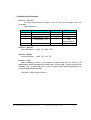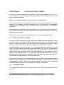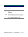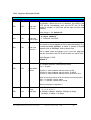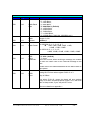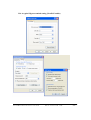
1
VW320A
VW321A
USER MANUAL (Rev 4.1)
VitalWell
Electronics Pte. Ltd.
V italWell Electronics Pte Ltd.
vital-well.com
T el: +86 -0756 -3867295
Block D3, #415/416, Southern Software Park, TangJia,, ZhuHa i, Ch ina 519080
Proprietary Notice:
© Copyright VitalWell Electronics Pte. Ltd., 2011
The information in this document is subject to change without notice.
Company or product names mentioned in this document may be trademarks or
registered trademarks of their respective companies.
All rights reserved. Neither the whole nor any part of the information contained in
this publication may be reproduced in any material form except with the written
permission of VitalWell Electronics Pte Ltd..
This publication is intended only to assist the reader in the use of the product.
VitalWell Electronics Pte Ltd. shall not be liable for any loss or damage arising
from the use of any information in this publication, or any error or omission in
such information, or any incorrect use of the product.
Technical Support:
Documentation is updated periodically. For the latest information about VitalWell
Electronics Pte Ltd. products, including software upgrades and application
information, please contact your local VitalWell Electronics Pte Ltd. Sales entity.
VitalWell Electronics Pte Ltd. provides customer technical support using phone
and/or e-mail means.
For customer technical support, please contact your local VitalWell Electronics
Pte Ltd. sales entity.
V italWell Electronics Pte Ltd.
vital-well.com
T el: +86 -0756 -3867295
Block D3, #415/416, Southern Software Park, TangJia,, ZhuHa i, Ch ina 519080
INTRODUCTION
The VW series Radio Modem provides the capability of a short range, reliable
wireless point-to-point, point-to-multipoint and mesh network RF data
communications link.
The VW series modem can be used in a variety of data communications
applications that require a simple to use invisible data link. The radio modem is
designed to interface to a variety of host devices. These devices include
computers, receipt printers, PLC’s, data loggers, SCADA devices and intelligent
control systems.
The serial data transferred over the radio link is not altered; the output serial data
stream is the same as the input serial data stream. The radio modems provide a
two-way data communications links, where each unit can accept serial data and
also output serial data.
The VW series radio modems are fully self-contained units, requiring only an
external +5VDC (or +3.3VDC) power source to operate. The radio modules used
in the radio modems have been selected to meet the requirements of unlicensed
operation in the international ISM bands, and are therefore acceptable for use in
many countries.
Features
§
§
§
§
§
§
§
§
§
§
§
4 operation modes: Transparent mode, Transparent secured mode,
Addressed mode and Addressed secured mode
Repeater supported
Deep sleep mode
Server-Client mode
Broadcast Multi-drop mode
Serial protocol format is 9600bps,8 data/1 stop/no parity.
Selectable flow control of software/none.
Selectable radio speed, channel and radio power.
On-air data encryption, error checking and data acknowledgements.
Easy configuration by AT commands.
Built in configuration and diagnostic functions.
This manual describes the electrical specifications and different functioning
modes available on the VW series. This description will also help you to
understand the principles behind the configuration registers and to use them
more efficiently.
V italWell Electronics Pte Ltd.
vital-well.com
T el: +86 -0756 -3867295
Block D3, #415/416, Southern Software Park, TangJia,, ZhuHa i, Ch ina 519080
CONTENTS
CHAPTER I
ELECTRICAL SPECIFICATION ……………………………1
CHAPTER II
CONFIGURATION MODE ……………………………………3
II.1 Entering Configuration Mode
II.2 Command Format
II.3 Configuration Commands in Detail
II.4 Registers Description
CHAPTER III
TRANSPARENT MODE
III.1 Operation
III.2 Examples
……………………………….……9
CHAPTER IV
TRANSPARENT SECURED MODE ……………………… 10
IV.1 Operation
IV.2 Examples
CHAPTER V
ADDRESSED MODE …………………………………………11
V.1 Operation
V.2 Examples
CHAPTER VI
ADDRESSED SECURED MODE …………… ………… …12
VI.1 Operation
VI.2 Examples
CHAPTER VII
ORDERING INFORMATION ………………………………...13
APPENDIX …………………………………………………………………………...14
A. Modems and boards Installation: Principles and cautions
B. Register setting tips and examples
B.1. Configuration list file
B.2. Turn on Software flow control (Xon/Xoff)
B.3. Changing Operation Mode
B.4. A typical point-point configuration using Addressed Mode
B.5. A typical Server-Client configuration using Addressed Mode
B.6. A typical Hyper-terminal setting (Xon/Xoff enable)
V italWell Electronics Pte Ltd.
vital-well.com
T el: +86 -0756 -3867295
Block D3, #415/416, Southern Software Park, TangJia,, ZhuHa i, Ch ina 519080
CHAPTER I
ELECTRICAL SPECIFICATION
I.1 General Specifications
1)Supply Voltage:+5V or +3.3V (±10%)
2)Supply Current: < 120mA(VW320A), <1A (VW321A)
3)Voltage level at I/O:+3.3V TTL( +5V compatible)
4):Serial Interface Characteristics (RS232)
i. Baud rate: 1200bps ~ 115.2kbps, ( 9600bps, 8N1, Default)
5)RF Characteristics:
i. Frequency band:ISM 433/868/915MHz
ii. Channels: 100
iii. RF rate:
1.2kbps, 2.4kbpa, 4.8kbps, 9.6kbps, 19.2kps,
38.4kbps, 76.8kbps, 115.2kbps
iv. Max RF transmitter power
VW320A: +20dB (100mW)
VW321A: +30dB (1W)
v. Sensitivity:-121dB (1.2kbps), -108dB(38.4kbps)
vi. Typical link range (outdoor) :
VW320A : >1000m @9600bps, L.O.S
VW321A: > 2000m @9600bps, L.O.S
6) Ready to Tx/Rx after power on reset: 150ms max
I.2 Dimension
232TTL:
1) (L X W X H): 41mm X 23mm X 5mm (PCB assembly, exclude connector)
2) Interface:
10pin; 2.0mm header
RS232C, RS485:
1) (L X W X H): 70mm x 50mm x 20mm (Metal casing)
2) Interface:
terminal block (screw)
USB:
(L X W X H): 83mm x 83mm x 25mm (Metal casing)
V it al We ll E l ectr on ics P t e Ltd
www.v it al-well .com
-1-
I.3 Interface Specifications
Interface : 232 TTL
The signal voltage level of VW320 is 3.3V TTL level at the interface, with +5V
compatible.
Signal Definitions:
Pin No.
1
2
3
4
Signal Name
GND
VCC (+5V)
RXD (RS232,TTL)
TXD (RS232, TTL)
Pin No.
6
7
8
9
5
IO0 (RS485 T/R)
10
Signal Name
IO1 (board ready)
IO2
IO3
IO4
(Sleep/WOR Ctl)
Boot loader /EN
Interface : RS232C
Signal Definitions: GND, +5V, RXD, TXD
Interface : RS485
Signal Definitions: GND, +5V, A, B, T/R
Interface : USB
After installing a driver, it will create a virtual serial port on the PC. All
applications, which designed for serial ports, will be able to work well with the
modules. E.g., It allows the PC to use a normal hyper-terminal application to
communicate with the module.
Connector: USB B-type connector
V it al We ll E l ectr on ics P t e Ltd
www.v it al-well .com
-2-
I.4
Typical Connections
1) 232TTL / RS232C (connections at Pin1~4 only)
1 (GND)
2 (+5V)
3(RXD)
4(TXD)
VW320A-232T, 232C
VW321A-232T, 232C
1(GND)
2 (+5V)
3(RXD)
4(TXD)
Host
2) VW320A-485, VW321A0485
VW320A-485
VW321A-485
1 (GND)
2 (+5V)
3( A)
4( B)
V it al We ll E l ectr on ics P t e Ltd
1 (GND)
2 (+5V)
3(A)
4(B)
www.v it al-well .com
-3-
CHAPTER II
CONFIGURATION MODE
For fast and easy configure the modems to suit various application, the user is
recommended to use our Config_Panel program which can be downloaded from our
web to modify the settings.
When in filed changes needed, the user can follow the notes below.
This section describes the configuration and test commands supported by the radio
modem. In most cases, once the configuration is set it will not need to be changed.
Configuration is performed using a serial terminal, or appropriate communication
application.
All commands and command values accepted by the radio modem are described in
this section; any entries other than those listed here results in an invalid command or
argument error message.
The first step to configuring the Radio Modem is to put it in Configuration Mode…
II.1
Entering Configuration Mode
A series of three consecutively typed characters, called an escape sequence, forces
the radio modem to exit data transfer mode and enter the modem configuration mode.
While in Configuration Mode, you can communicate directly with the radio modem
using a number of specific commands to configure and test the radio modem.
The escape sequence is factory set to ‘+++’ (No carriage return key is followed). A pause
length of which is called the escape guard time (about 1s) must be completed both
before and after when escape sequence is entered. These three '+' characters must
not be sent as one continued frame. The delay between any 2 characters must be
between 20ms~200ms for the (‘+++’) sequence. This prevents the radio modem from
interpreting the escape sequence as data and the vice versa. The guard time must also
be met when the Radio Modem is initially powered up.
Configuration changes are stored permanently in non-volatile memory within the Radio
Modem. Exiting Configuration Mode and returning back to data transfer mode is
accomplished by typing “ATO” at the command prompt. This will force a soft reset of
the Radio Modem resulting in any configuration changes taking effect.
II.2
Command Format
VW modem’s parameters are set through the use of AT type commands sent on the
serial link.
V it al We ll E l ectr on ics P t e Ltd
www.v it al-well .com
-4-
'AT' commands complies with Hayes protocol used in PSTN modem standards. This
‘AT’ protocol is used to configure the modem parameters, based on the following
principles :
A data frame always begins with the two ASCII ’AT’ characters, standing for
‘ATtention’,
_ Commands are coded over one or several characters and may include additional
data
_ A given command always ends up with a < CR> Carriage Return
AT
Command
Additional data
<CR>
Note: The delay between 2 characters of the same command must be less than
30 seconds
All alphabetical characters typed in configuration command mode are converted to
upper case before being interpreted by the configurator. Thus commands can be typed
using either upper or lower case.
Despite its similarity to standard telecommunication modem, it remains a radio link
modem and is consequently fitted with some particular and specific ‘AT’ commands
proper to radio transmission (I.e. communication channel, radio rate...).
V it al We ll E l ectr on ics P t e Ltd
www.v it al-well .com
-5-
II.3
Configuration Commands in Detail
Command
Description
Operating mode
Configuration Mode Activation
+++
‘+++’ Command gives an instant access to the modem’s
parameters configuration mode (AT mode).
‘+++’ Command should be entered one by one. The time between two ‘+’
must be between 50ms ~200ms.
Answer: >
Communication mode activation
ATO
‘ATO’ command gives an instant access to the modem’s
Operating mode.
‘ATO’ command is used to get out of Configuration Mode.
And Parameters will be saved to on-chip non-volatile memory.
Answer: Good Bye!
Communication mode activation
ATX
‘ATX’ command gives an instant access to the modem’s
Operating mode.
‘ATX’ command is used to get out of Configuration Mode.
And Parameters will NOT be saved to on-chip non-volatile memory, and
only changed in RAM. After reset, it will restore the previous saved
parameters.
Answer: Good Bye!
V it al We ll E l ectr on ics P t e Ltd
www.v it al-well .com
-6-
Command
Description
Register Handling
‘AT/V’ command displays the modem’s firmware version number similar
as follows:
AT/V
AT/L
ATSn=m
Or
VW4432A-4 V2.0
B/N: 20110727
>
‘AT/L’ command displays a dynamic and clear status of all relevant
registers of the modem with the following categories:
_ Serial link,
_ Radio,
_ Operation Mode,
_ Network
‘ATSn=m’ or ‘ATSn=m.k’ command configures register number n with
the value m (or m.k, if 2 Bytes), e.g. ATS100=32<CR> enters the value
‘32’ in the register S100; ATS120=192.168 enter the value ‘192.168’ in
the register S120. The value of m & k is between 0~255.
ATSn=m.k
Answer: > or ??(CR) > if the configuration is not valid
V it al We ll E l ectr on ics P t e Ltd
www.v it al-well .com
-7-
II.4
Registers Description
The parameters to be configured via Configuration mode are stored in modem’s
memory registers, called S registers. Those registers are always listed as follows:
_ S10x registers correspond to the serial parameters,
_ S110x registers correspond to the radio parameters,
_ S12x registers correspond to the general/ network operation parameters,
The standard registers and their use are shown in the next table.
V it al We ll E l ectr on ics P t e Ltd
www.v it al-well .com
-8-
II.4.1 Registers Description Table
Serial Link
Access Registers
R/W
S100
Name
Serial Link
FIFO size
Description
Indicates the maximum frames size that will be given to
the Modem. When this size is reached, the data in the
FIFO will be immediately sent out via RF link (If flow
control is enable, a Xoff code will be sent out from the
modem).
Value Range: 1~50, Default: 50
R/W
R/W
S101
S102
Serial Link
Flow Control
Serial Link
Time Out
Indicates flow control type:
_ '0': None (default)
_ '1': Software: Xon/Xoff,
Indicates the value of the time-out on the serial link ( time
out counts on bytes lapsed on the current baudrate). E.g:
at serial baudrate 9600bps, a value ‘5’ means a 5bytes
transmit time on 9600bps, that is: about 5ms.
This is used: when the serial FIFO is not full, after this
time out, the data in the FIFO will be sent out via RF link.
Value Range: 3~255
Default: 3
Sleep Mode Control: (for 232TTL version)
0 – Disable (Default), module always active
1,2,3 – Enable
R/W
S103
Sleep Mode
Control
If S103=1, sleep enabled, wakeup active by IO4
If S103=2, sleep enabled, wakeup active by WOR
If S103=3, sleep enabled, wakeup active by WOR or IO4
And: I/O1(output) will be used to indicate the working status:
I/O1 = 0: indicate a active status
I/O1 = 1: indicate a power down mode
See more details on appendix c.
R/W
S104
Serial
Baud Rate
V it al We ll E l ectr on ics P t e Ltd
Serial Baud Rate
0, 1, 2, 3, 4, 5, 6, 7
-> 1200bps, 2400bps, 4800bps, 9600bps,19.2kbps,
38.4kbps, 57.6kbps, 115.2kbps
www.v it al-well .com
-9-
Radio
Access
Registers
R/W
S110
R/W
S111
R/W
S112
R/W
S115
Name
Description
Set the speed on the Radio:
_ '0': 1200 Bits/s,
_ '1': 2400 Bits/s,
Radio Baud _ '2': 4800 Bits/s,
_ '3': 9600 Bits/s, (Default)
Rate
_ '4': 19200 Bits/s,
_ '5': 38400 Bits/s,
_ '6': 76800 Bits/s,
_ ‘'7': 115200 Bits/s,
_ '8': 256000 Bits/s (VW110A, VW2500A only)
Number of the radio channel in use.
Radio
Range: 0~100
Channel
Default: 0
Power of the Radio.
For VW320A: 0, 1, 2, 3, 4, 5, 6, 7
Radio Power
è +1dB, +2dB, +5dB, +8dB, +11dB,
+14dB, +17dB, +20dB
For VW321A: 0, 1, 2, 3, 4, 5,
+18dB, +20dB, +21dB, +23dB, +25dB, +30dB
RSSI
Value
show/hide
_ '0': hide (default)
_ '1': show
When set to show, when receiving a message, the modem
will echo the RSSI value of the received message to the
host.
Please refer to the Si4432 datasheet for the RSSI value Vs
input power
Setting W.O.R timer when register S103 =2 or 3
R/W
S116
WOR
Timer
Step is 200ms
Exp: when S116=10, means the board will auto wakeup
every 2s to listen a wakeup beacon signal. If no, then auto
back to sleep mode; if yes, will pull IO1 to low.
See more details on appendix c.
V it al We ll E l ectr on ics P t e Ltd
www.v it al-well .com
- 10 -
Operation & Network
Access
Registers
Name
Description
Network ID in 2 Bytes.
R/W
S120
Network ID
E.g.: ATS120=192.168 will set the network ID to 192.168
R/W
S121
Device ID
Device ID (Used for Addressed Mode or Addressed Secured
Mode).
R/W
S122
Default
Destination
Device ID
Default Destination Device ID (Used for Addressed Mode or
Addressed Secured Mode). If Destination ID is not provided
in the payload, data will sent to this address.
R/W
S123
Group ID
Group ID (Used only for Transparent Mode or Transparent
Secured Mode).
All and only devices with the same cluster id (together with
the network id) will be linkable.
Operation Mode:
R/W
S124
Operation
Mode
_’0’ Transparent Mode (default)
_ ‘1’ Transparent Secured Mode
_ ‘2’ Addressed Mode
_ ‘3’ Addressed Secured Mode
_ ‘10’ Testing mode, in this mode, the module will
automatically transmit a pre-defined string once a
second. It can be used to test the linkage range without
a host.
_’20’ : test mode 2, used for pattern test. During this
mode, the modem will Tx a 20byte’s 0x00, 0x01, 0x00,
0x01,…. Data stream once a second.
_’21’: test mode 3 (Tx un-modulated carrier signal)
_’22’: test mode 4 (Tx GFSK-modulated spectrum
signal)
R/W
S125
Number of
Retries
Number of recoveries counts in case of radio conflicts
(Used for Addressed Secured /Transparent Secured Mode).
Default: 3
Indicates whether Address at the header. Bit 0 for TX, bit 1
for RX. ( For addressed mode only)
R/W
S126
Address at
the Header
(TX & RX)
Bit 0:
_ '0': Data will be sent to default address (Register S123);
V it al We ll E l ectr on ics P t e Ltd
www.v it al-well .com
- 11 -
_ '1': Decode the target address from the header when TX.
Bit 1:
_ ’0’: when receive, forward the payload without address.
_ ’1’: when receive, add the message’s source address
at the header together with payload (default)
E.g.: When S126=1or 3, the‘10=ABCD’ inputs, will sent data
‘ABCD’ to address 10; when S126=2 or 3, the output
“2=ABCD” means the data come from address 2.
Indicates the acknowledgment handling method (Used for
Addressed/Transparent Secured Mode).
(Only the lower 4bits in this byte will be R/W. the upper 4 bits
is used by system to indicate the RF acknowledgment
status).
R
Or
S127
Echo back
Ack to host
R/W
_ '0': No (Default), OK or fail signal is not sent to Host
_ '1': OK or fail signal will be sent to host
By default, in case of problems, the modem will retry
automatically for the numbers (which set by register S125),
but doesn’t assert the signals to host. If enable, after each
successful transmission, a Synchronize byte (0x16) will be
sent out; if after retry still fail, a NAK byte (0x15) will be sent
to the host.
R/W
S128
Node Type
R/W
S129
Repeater
Enable
Node Type:
‘0’: Normal node (not intent to route a message)
’1’: Repeater node (This is a repeater, and will route any
message it received)
Repeater Enable control:
‘0’ : Disable
‘1’: Enable
If S129 = 1, the TX package will automatically routed to &
via the repeater(address defined by S130)
R/W
S130
Repeater
Address
Repeater Address:
If S129 =1, this register will set the desired repeater’s
address. All Tx package will be send to this node first, and
the repeater will automatically route the package to the
desired destination.
V it al We ll E l ectr on ics P t e Ltd
www.v it al-well .com
- 12 -
CHAPTER III TRANSPARENT MODE
The transparent mode is the default communication mode, based on a null-modem
cable emulation. Basically, the modems in transparent mode is equivalent to a halfduplex module and reproduces the half-duplex function of a RS-485 , RS-232 or RS422 cable.
This mode can be used as Point to Point or Point to Multi-point with all the modems
receiving the messages sent by any modem.
III.1
Operation
Radio modems in transparent mode behave like wired serial links. Therefore, radio
modems automatically transmit every serial data received on their radio link, and also
transmit all radio information received on their serial link. The transparent mode can be
operated for both point-to-point and multipoint links.
The software flow control (Xon/Xoff) can be enabling for this mode if the user want to
send a large block data in this mode.
However, no flow control on the radio link is performed by the radio modems in
transparent mode. Therefore, the data control must then be carried out by software
applications used by various protocols such as ProfiBus, ModBus, etc… Consequently,
the latency time is reduced to its minimum as the modem no needs wait to check the
acknowledgment byte.
Any unit, with the same network ID and group ID, configured in transparent mode will
receive every radio data flowing on the same communication channel, i.e. on the same
frequency.
III.2
Examples - Configuration with AT commands
User
Modem
User
Modem
User
Modem
User
Modem
User
Modem
+++
>
ATS120=192.168<CR>
>
ATS123=120<CR>
>
ATS124=0<CR>
>
ATO<CR>
Good Bye!
V it al We ll E l ectr on ics P t e Ltd
// Switch to Configuration mode
// Set network ID to 192.168
// set cluster id to 120
// Transparent mode selection,0
// Switch to operating mode
www.v it al-well .com
- 13 -
CHAPTER IV TRANSPARENT SECURED MODE
In order to confirm the good quality of transmitted data frames and to avoid data loss,
data frame control between radio modems are added to the transparent mode, so that
each data transfer is verified.
IV.1
Operation
Transparent secured mode’s purpose is to offer an optimal radio link quality and to
provide transparent mode with the necessary security in case frame control would not
be included within the user’s application software. The risk of data loss is therefore
much weaker. Moreover, a flow control, Xon/Xoff can be enabling to be performed on
the serial link in order to warn the user that the data buffer is saturating.
The receiving unit analyses this data frame and checks its consistency, When the data
frame is received correctly, the receiver transmits an Acknowledgement back to the
transmitter, and delivers the received data frame to its serial link.
In case the reception is not satisfying, no acknowledgement is received by the
transmitter. The transmitter then repeats the data frame transmission after a random
delay. The number of iterations can be configured via S126 register.
Transparent secured mode shall be operated for point-to-point communications
only.
At serial port level, the statements of whether the data frame has been transmitted or
not can be asserted to the user by enable the bit in S128 register.
IV.2
Examples - Configuration with AT commands
User
Modem
User
Modem
User
Modem
User
Modem
User
Modem
+++
>
ATS120=192.168<CR>
>
ATS123=120<CR>
>
ATS124=1<CR>
>
ATO<CR>
Good Bye!
V it al We ll E l ectr on ics P t e Ltd
// Switch to Configuration mode
// Set network ID to 192.168
// set cluster id to 120
// Transparent Secure mode
// Switch to operating mode
www.v it al-well .com
- 14 -
CHAPTER V ADDRESSED MODE
The addressed mode is similar to a multipoint mode. All modems can communicate
with each other by addressing each frame to one of them.
V.1
Operation
Addressed mode’s purpose is to offer an optimal radio link performance providing the
multipoint access of the transparent mode.
Compared to the transparent mode, the addressed mode therefore includes the
additional feature to address each data frame to a specific modem.
When enabled, the modem can identifie the clients with a specific number added at the
beginning of each data frame. For example: "1=Hello" sends the data frame "Hello" to
Client 1.
The address header can be omitted by setting the address_at_the_header control
register S127 to 0 (ATS127=0). Then all of the data frames will be sent to the default
address (register S123). This is useful when in a server-client configuration; all clients
set the default address to their server address. For example, when S127=0, S123=1,
“Hello” sends the data frame “Hello” to server 1.
Receiver client recognizes the Client transmitting modem by decoding the data frame
and send the data frame to its serial link. When enabled, the modems can inform the
hosts with a specific number added at the beginning of each data frame received. For
example: "2=Hello" indicates that data frame "Hello" comes from Client 2.
The software flow control (Xon/Xoff) can be enabled (ATS101=1) on its serial link.
V.2
User
Modem
User
Modem
User
Modem
User
Modem
User
Modem
User
Modem
User
Modem
Examples - Configuration with AT commands
+++
// Switch to Configuration mode
>
ATS120=192.168<CR>
// Set network ID to 192.168
>
ATS121=10<CR>
// set device id to 10
>
ATS122=11<CR>
// set default destination id to 11
>
ATS124=2<CR>
// Addressed mode
>
ATS126=0<CR>
// no address header, data will be sent to the default
>
ATO<CR>
// Switch to operating mode
Good Bye!
V it al We ll E l ectr on ics P t e Ltd
www.v it al-well .com
- 15 -
CHAPTER VI ADDRESSED SECURED MODE
The addressed secured mode is similar to a addressed mode, but with
acknowledgment handling on the radio.
VI.1
Operation
Addressed secured mode’s purpose is to offer an optimal radio link quality. Compared
to the addressed mode, the addressed secured mode therefore includes the additional
feature to retransmit the data frame in case of radio collisions.
All the address handling method is identified with the addressed mode. And, the radio
acknowledgment handling method is identified with the transparent secured mode.
The software flow control (Xon/Xoff) can be enabled (ATS101=1) on its serial link.
VI.2
User
Modem
User
Modem
User
Modem
User
Modem
User
Modem
User
Modem
User
Modem
User
Modem
User
Modem
Examples - Configuration with AT commands
+++
// Switch to Configuration mode
>
ATS120=192.168<CR>
// Set network ID to 192.168
>
ATS121=10<CR>
// set device id to 10
>
ATS122=11<CR>
// set default destination id to 11
>
ATS124=3<CR>
// Addressed Secured mode
>
ATS125=3<CR>
// set the retries=3 in case of collision
>
ATS126=0<CR>
// no address header, data will be sent to the default
>
ATS127=0<CR>
// no echo back host for the acknowledge
>
ATO<CR>
// Switch to operating mode
Good Bye!
V it al We ll E l ectr on ics P t e Ltd
www.v it al-well .com
- 16 -
CHAPTER VII
ORDERING INFORMATION
Ordering Code:
Code
VW320A-232T-X
Description
VW320A, Interface: 232 TTL
VW320A -232C-X
VW320A, Interface:
RS232C
VW320A -485-X
VW320A, Interface:
RS485
VW320A -USB-X
VW320A, Interface:
USB
VW321A-232T-X
VW321A, Interface:
232 TTL
VW321A -232C-X
VW321A, Interface:
RS232C
VW321A -485-X
VW321A, Interface:
RS485
VW321A -USB-X
VW321A, Interface:
USB
Where:
X = 4: Frequency band at 433MHz ISM
X = 8: Frequency band at 868MHz ISM
X = 9: Frequency band at 915MHz ISM
V it al We ll E l ectr on ics P t e Ltd
www.v it al-well .com
- 17 -
APPENDIX
A.
Modems and boards Installation: Principles and cautions
_ The radio environment should be closely studied prior to any installation in order to
determine whether and where the installation will be optimal.
_ The modems should be located as high and as free as possible so that a line of sight
propagation is established between modems to achieve a better radio link.
_ The modem should not be surrounded by metallic masses because of the
disturbances caused by a reflection phenomena.
_ The electrical disturbances can come from various sources and should be avoided:
_ Engines
_ High current devices
_ Power relays
_ Transformers
_ Etc…
_ Vibrations and/or shocks can also be source of disturbances. It is therefore advised
to mount the modems on silent-blocks in order to stabilize it whenever necessary.
V it al We ll E l ectr on ics P t e Ltd
www.v it al-well .com
- 18 -
B.
Register setting tips and examples
B.1. Configuration list file
You can put a typical setting list into .txt file. After commanding the modem into
configuration mode, you can send this file to modem via serial link (In hyper
terminal, this is done by choosing: Transfer -> Send Text File…). Then later you
can just only adjust 1 or 2 registers’ settings depending on the requirement. Or,
you may just want to confirm the settings by enter “AT/L” to have a setting’s list.
After everything is confirmed, you can enter “ATO” and press the “Enter” key to
leave the configuration mode to operation mode.
Here is a typical setting list file for a transparent mode:
<Setting.txt>
ATS100=60
ATS101=1
ATS102=5
ATS110=3
ATS111=0
ATS112=3
ATS120=192.168
ATS121=100
ATS122=200
ATS123=127
ATS124=0
ATS125=3
ATS126=0
ATS127=0
(End)
B.2. Turn on Software flow control (Xon/Xoff)
ATS101=1
B.3. Changing Operation Mode
ATS124=m
(m=0,1,2,3)
V it al We ll E l ectr on ics P t e Ltd
www.v it al-well .com
- 19 -
B.4. A typical point-point configuration using Addressed Mode
<Client1>
ATS100=60
ATS101=1
ATS102=5
ATS110=3
ATS111=0
ATS112=3
ATS120=192.168
ATS121=100
ATS122=200
ATS123=127
ATS124=2
ATS125=3
ATS126=0
ATS127=0
// you can turn off Xon/Xoff by ATS101=0
// device ID
// default destination id
// Addressed Mode
//no address at the header
<Client2>
ATS100=60
ATS101=1
ATS102=5
ATS110=3
ATS111=0
ATS112=3
ATS120=192.168
ATS121=200
ATS122=100
ATS123=127
ATS124=2
ATS125=3
ATS126=0
ATS127=0
V it al We ll E l ectr on ics P t e Ltd
// you can turn off Xon/Xoff by ATS101=0
// device ID
// default destination id
// Addressed Mode
//no address at the header
www.v it al-well .com
- 20 -
B.5. A typical Server-Client configuration using Addressed Mode
<Server>
ATS100=60
ATS101=1
ATS102=5
ATS110=3
ATS111=0
ATS112=3
ATS120=192.168
ATS121=10
ATS122=200
ATS123=127
ATS124=2
ATS125=3
ATS126=3
ATS127=0
// you can turn off Xon/Xoff by ATS101=0
// device ID, server ID=10
// default destination id, dummy for server
// Addressed Mode
//client address at the header, for server
<Client 1>
ATS100=60
ATS101=1
…
ATS120=192.168
ATS121=1
ATS122=10
…
ATS124=2
…
ATS126=0
ATS127=0
// you can turn off Xon/Xoff by ATS101=0
// device ID, client id=1
// default destination id, the server ID
// Addressed Mode
//no address at the header, default to/from server; for client
<Client 2>
ATS100=60
ATS101=1
…
ATS120=192.168
ATS121=2
ATS122=10
…
ATS124=2
…
ATS126=0
ATS127=0
// you can turn off Xon/Xoff by ATS101=0
// device ID, client id=2
// default destination id, the server ID
// Addressed Mode
//no address at the header, default to/from server; for client
On server, "1=Hello" sends the data frame "Hello" to Client 1. "2=Hello" sends the data
frame "Hello" to Client 2. On each client, “Hello” sends the data frame “Hello” to server
(ID=10).
V it al We ll E l ectr on ics P t e Ltd
www.v it al-well .com
- 21 -
B.6. A typical Hyper-terminal setting (Xon/Xoff enable)
V it al We ll E l ectr on ics P t e Ltd
www.v it al-well .com
- 22 -
C.
Sleep mode notes
This operation is for VW320A-232T only.
VW320 series are built-in with configurable sleep modes to suit various
applications.
When go to sleep mode, the board can be waked up by
1) I/O pin (S103 = 1, sleep mode 1)
2) W.O.R timer only (S103 = 2,, sleep mode 2)
3) Both
(S103 = 3, sleep mode 3)
IO4 (pin 9) is used to wakeup board when pin wakeup mode is enabled (S103
=1 or 3). A falling edge on IO4 will wake up board from sleep mode. IO4 should
be kept low to keep the board be in active mode. A rising edge will put the
board back to sleep mode.
VW320 have another wakeup event: WOR functions.
When WOR sleep mode enabled ( WOR timer be set at S116 @200ms step ),
the board will auto wakeup by a WOR timer overflow, and will auto listen a
mater’s WOR beacon signal. If yes, the board will info the external MCU by pull
down IO1, and is kept active at least for 0.2s. When the external MCU received
the IO1 low signal, and need the board be kept active to complete some task, it
should pull IO4 to low. A rising edge on IO4 will put the board back to sleep
mode, and WOR timer will restart; if no response from the external MCU after
pull IO1 to low, the board will auto go to sleep mode after 200ms, and also the
WOR will restart.
When in sleep mode, IO1 will be push to high.
How to wake up a WOR enabled slave?
The master should set S103=0. Then a falling edge on IO4 will trigger a WOR
wakeup beacon event. The master will continues send out a series beacon
(time is defined by S116). The value of S116 of master should >= slaves’ S116
to ensure a successful wakeup.
V it al We ll E l ectr on ics P t e Ltd
www.v it al-well .com
- 23 -
D.
Boot loader notes
(VW320A series)
VW320A is equipped with a boot loader when shipped out from factory.
It allow the firmware be upgraded after receive the board.
Users can request to alter the default firmware to suit their special application
after receiving the board. Depending on the request, we, Vitalwell will evaluate it
and do the changes accordingly. The modified firmware will be sent out by email.
The boot loader is active by keep pin10 to low during power up. When boot
loader is active, the on board LED will flash fast to indicate a ready to receive
new firmware state.
The firmware is send to board via a serial COM connection. PC application for
the boot loader is available.
Firmware uploader’s interface
V it al We ll E l ectr on ics P t e Ltd
www.v it al-well .com
- 24 -
Document History
a)
b)
c)
d)
e)
f)
Rev 1.0:
Rev 2.0:
Rev 2.2:
Rev 2.3:
Rev 2.4:
Rev 2.5:
g)
h)
i)
k)
Rev 2.5A:
Rev 2.5B:
Rev 3.0:
Rev 3.1:
l)
Rev 3.2:
j) Rev 4.0:
k)
Rev 4.1
Initial release, for VW1203A
Add VW1100A & VW2500A
Add ordering information
Add FEC control register for VW1100A & VW2500A
Add VW1205A
i) Add sleep mode( - 232T, S103) & testing mode(S124)
ii) Signal at Pin 9 changed.
iii) Repeater function (S128 ~S130)
Correct some typing error.
Description changes on register S102.
Add VW4432A
change notes for register S112, Add register S104; other minor
changes
1) Change notes for Register S124
2) Add notes for register S115 (RSSI value show/hide control)
3) add notes for time of ready to Tx/Rx after P.O.R
1) separate manual for VW320
2) Change notes for register S103 (sleep control)
3)Add Register S116 (W.O.R timer control)
4) notes for boot loader.
5) new ATX command added (page 5)
1) add notes for VW321A
V it al We ll E l ectr on ics P t e Ltd
www.v it al-well .com
- 25 -
Vita lWell Electronics Pte Ltd.
Tel: +86-0756-3867295
Block D3, #415/416, Southern Software Park, TangJia,, ZhuHai, China 519080
vital-well.com