1
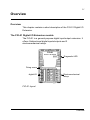
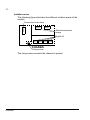
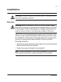
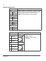
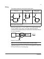
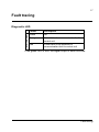
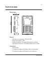
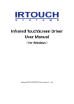
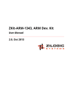
ABB Drives
User’s Manual
Digital I/O Extension
FIO-01
Digital I/O Extension
FIO-01
User’s Manual
3AFE68784921 Rev C
EN
EFFECTIVE: 05.06.2008
© 2008 ABB Oy. All Rights Reserved.
5
Safety instructions
Overview
This chapter states the general safety instructions that must be
followed when installing and operating the FIO-01 Digital I/O
Extension.
In addition to the safety instructions given below, read the
complete safety instructions of the specific drive you are working
on.
These warnings are intended for all who work on the drive.
Ignoring the instructions can cause physical injury or death, or
damage the equipment.
General safety instructions
Warning! All electrical installation and maintenance work on the
drive should be carried out by qualified electricians only.
The drive and adjoining equipment must be properly earthed.
Do not attempt any work on a powered drive. After switching off
the mains, always allow the intermediate circuit capacitors to
discharge for 5 minutes before working on the frequency
converter, the motor or the motor cable. It is good practice to
check (with a voltage indicating instrument) that the drive is in fact
discharged before beginning work.
The motor cable terminals of the drive are at a dangerously high
voltage when mains power is applied, regardless of motor
operation.
There can be dangerous voltages inside the drive from external
control circuits even when the drive mains power is shut off.
Exercise appropriate care when working on the unit.
Safety instructions
6
Safety instructions
7
Table of Contents
Safety instructions . . . . . . . . . . . . . . . . . . . . . . . . . . . . . . . . . . . . . . . . . . . . 5
Overview . . . . . . . . . . . . . . . . . . . . . . . . . . . . . . . . . . . . . . . . . . . . . . . . . . . . 5
General safety instructions . . . . . . . . . . . . . . . . . . . . . . . . . . . . . . . . . . . . . . . 5
Table of Contents . . . . . . . . . . . . . . . . . . . . . . . . . . . . . . . . . . . . . . . . . . . . . 7
Introduction . . . . . . . . . . . . . . . . . . . . . . . . . . . . . . . . . . . . . . . . . . . . . . . . . 9
Intended audience . . . . . . . . . . . . . . . . . . . . . . . . . . . . . . . . . . . . . . . . . . . . . 9
Before you start . . . . . . . . . . . . . . . . . . . . . . . . . . . . . . . . . . . . . . . . . . . . . . . 9
What this manual contains . . . . . . . . . . . . . . . . . . . . . . . . . . . . . . . . . . . . . . . 9
Product and service inquiries . . . . . . . . . . . . . . . . . . . . . . . . . . . . . . . . . . . . 10
Product training . . . . . . . . . . . . . . . . . . . . . . . . . . . . . . . . . . . . . . . . . . . . . . 10
Providing feedback on ABB Drives manuals . . . . . . . . . . . . . . . . . . . . . . . . 10
Overview . . . . . . . . . . . . . . . . . . . . . . . . . . . . . . . . . . . . . . . . . . . . . . . . . . . 11
Overview . . . . . . . . . . . . . . . . . . . . . . . . . . . . . . . . . . . . . . . . . . . . . . . . . . . 11
The FIO-01 Digital I/O Extension module . . . . . . . . . . . . . . . . . . . . . . . . . . . 11
Installation . . . . . . . . . . . . . . . . . . . . . . . . . . . . . . . . . . . . . . . . . . . . . . . . . 13
Mounting . . . . . . . . . . . . . . . . . . . . . . . . . . . . . . . . . . . . . . . . . . . . . . . . . . .
Terminal designations . . . . . . . . . . . . . . . . . . . . . . . . . . . . . . . . . . . . . . . . .
Wiring . . . . . . . . . . . . . . . . . . . . . . . . . . . . . . . . . . . . . . . . . . . . . . . . . . . . . .
Programming . . . . . . . . . . . . . . . . . . . . . . . . . . . . . . . . . . . . . . . . . . . . . . . .
13
14
15
16
Fault tracing . . . . . . . . . . . . . . . . . . . . . . . . . . . . . . . . . . . . . . . . . . . . . . . . 17
Diagnostic LED . . . . . . . . . . . . . . . . . . . . . . . . . . . . . . . . . . . . . . . . . . . . . . 17
Technical data . . . . . . . . . . . . . . . . . . . . . . . . . . . . . . . . . . . . . . . . . . . . . . 19
Table of Contents
8
Table of Contents
9
Introduction
Intended audience
The manual is intended for the people who are responsible for
commissioning and using the FIO-01 Digital I/O Extension. The
reader is expected to have a basic knowledge of electrical
fundamentals, electrical wiring practices and how to operate the
drive.
Before you start
It is assumed that the drive is installed and the drive power supply
is switched off before starting the installation of the extension
module. Ensure that all dangerous voltages connected from
external control circuits to the inputs and outputs of the drive are
switched off.
In addition to conventional installation tools, have the drive
manuals available during the installation as they contain important
information not included in this manual. The drive manuals are
referred to at various points of this document.
What this manual contains
This manual contains information on the wiring, configuration and
use of the FIO-01 Digital I/O Extension.
Safety instructions are featured in the first few pages of this
manual.
Overview contains a short description of the FIO-01.
Installation contains instructions for hardware settings, mounting
and cabling.
Fault tracing explains LED indications.
Technical data contains detailed technical information.
Introduction
10
Product and service inquiries
Address any inquiries about the product to your local ABB
representative, quoting the type code and serial number of the unit
in question. A listing of ABB sales, support and service contacts
can be found by navigating to www.abb.com/drives and selecting
Sales, Support and Service network.
Product training
For information on ABB product training, navigate to
www.abb.com/drives and select Training courses.
Providing feedback on ABB Drives manuals
Your comments on our manuals are welcome. Go to
www.abb.com/drives and select Document Library – Manuals
feedback form (LV AC drives).
Introduction
11
Overview
Overview
This chapter contains a short description of the FIO-01 Digital I/O
Extension.
The FIO-01 Digital I/O Extension module
The FIO-01 is a general purpose digital input/output extension. It
offers 4 bidirectional digital inputs/outputs and 2
electromechanical relays.
FIO-01
DIGITAL IO EXTENSION
Diagnostic-LED
STATUS
DIO1
COM
X61
1 2
DIO2
COM
X62
1 2
DIO3
COM
X63
1 2
DIO4
COM
X64
RO1NO
RO1COM
RO1NC
X65
RO2NO
RO2COM
RO2NC
X66
3 2 1
1 2
digital I/O
CHASSIS
3 2 1
Fixing screw
Electromechanical
relays
FIO-01 layout
Overview
12
Isolation areas
The following figure describes the different isolation areas of the
module.
Connection to the drive
X66
X201
X65
Electromechanical
relays
Digital I/O
X61 X62 X63 X64
CHASSIS
Fixing screw
The fixing screw connects the chassis to ground.
Overview
13
Installation
Warning! Follow the safety instructions given in this guide and in
the drive’s hardware manual.
Mounting
Warning! Before installation, switch off the drive power supply.
Wait for five minutes to ensure that the capacitor bank of the drive
is discharged. Switch off all dangerous voltages connected from
external control circuits to the inputs and outputs of the drive.
The FIO-01 is to be inserted into the option slot of the drive. The
module is held in place with plastic retaining clips and one screw.
On installation of the module, the signal and power connection to
the drive is automatically made through a 20-pin connector.
Mounting procedure:
• Insert the module carefully into the option slot until the retaining
clips lock the module into position.
• Fasten the screw (included) to the stand-off.
Note: Correct installation of the screw is essential for fulfilling the
EMC requirements and for proper operation of the module.
Installation
14
Terminal designations
Marking
Description
X61
• DIOx = Digital I/O. Input (default), push-pull or open
collector. Selection is made by parameter. See the
drive firmware manual for more information.
• COM = Ground reference on option board
1
DIO1
2
COM
X62
1
DIO2
2
COM
X63
1
DIO3
2
COM
X64
1
DIO4
2
COM
Marking
Description
1
RO1NO
2
RO1COM
3
RO1NC
Relay 1
X65
Installation
1
RO2NO
2
RO2COM
3
RO2NC
Relay 2
X66
• ROxNO = Relay normally open
• COM = Common
• ROxNC = Relay normally
connected
15
Wiring
The diagram presents some typical output types.
Open collector
(Sinking)
Push-pull
+24 V
VCC
VCC
RL1
+24V
Open emitter
(Sourcing)
VCC
RL
DIOx
DIOx
DIOx
RL
RL2
COM
COM
COM
VCC = Digital I/O power supply voltage
RL = Load at output channel
Maximum cable size is 1.5 mm2 (AWG 16) for digital signals and
2.5 mm2 (AWG 14) for relays. The cable shields should be
connected to the nearest ground. See the drive Hardware Manual
for more information.
+
-
DIOx
2 kOhms
“0” / ”1”
COM
Digital I/O description
Note: Do not route signal cables parallel to power cables.
Tightening torque is 0.3 N·m (2.7 lbf·in) for the digital I/O plugs and
0.5 N·m (4.4 lbf·in) for the relay plugs.
Installation
16
Programming
The communication between the module and the drive is activated
by a drive parameter. See the drive Firmware Manual.
Note: The new settings take effect only when the module is
powered up.
Installation
17
Fault tracing
STATUS LED
Diagnostic LED
Colour
Description
Green
OK
Orange
Not initialized or communication fault to
control unit
Red
Power fault & not initialized or
communication fault to control unit
If the green LED is unlit, the digital output is short circuited.
Fault tracing
18
Fault tracing
19
Technical data
Dimensions
32 mm
1.26 in
FIO-01
DIGITAL IO EXTENSION
106 mm
4.17 in
STATUS
1 2
DIO2
COM
X62
1 2
DIO3
COM
X63
1 2
DIO4
COM
X64
23 mm
0.91 in
RO1NO
RO1COM
RO1NC
X65
RO2NO
RO2COM
RO2NC
X66
3 2 1
1 2
DIO1
COM
X61
3 2 1
CHASSIS
63 mm
2.48 in
General
• Max. power consumption: 350 mA at 24 V
• Degree of protection: IP20
• Ambient conditions: The applicable ambient conditions
specified for the drive in its Hardware Manual are in effect
Connectors
• 20 pin socket
• 3.5 mm pitch header with 2 poles, total of 4 connectors
• 5.0 mm pitch header with 3 poles in two connectors.
Technical data
20
Digital I/O
• All DIOs programmable as
- Input (default)
- Push-pull output
- Open collector output
• Input voltages max 30 V, reverse polarity protection
• 24 V logic levels for input: “0” < 5 V, “1” > 15 V (according to
standard IEC 61131-2)
• Input impedance 2 kOhms
• Output current 50 mA source, 500 mA sink
• Outputs are short-circuit proof
• Galvanic isolation as one group
Relays
• 240 VAC, 2 A resistive load
• 30 VDC, 5 A resistive load
• Varistors for inductive load protection.
• Reinforced isolation between channels and channel and ground
Technical data
3AFE68784921 Rev C EN
EFFECTIVE: 05.06.2008
ABB Oy
AC Drives
P.O. Box 184
FIN-00381 HELSINKI
FINLAND
Telephone +358 10 22 11
Telefax
+358 10 22 22681
Internet
www.abb.com
ABB Inc.
Automation Technologies
Drives & Motors
16250 West Glendale Drive
New Berlin, WI 53151
USA
Telephone
262 785-3200
800-HELP-365
Telefax
262 780-5135
ABB Beijing Drive Systems
Co. Ltd.
No. 1, Block D,
A-10 Jiuxianqiao Beilu
Chaoyang District
Beijing, P.R. China, 100015
Telephone +86 10 5821 7788
Fax
+86 10 5821 7618