1
Freescale Semiconductor, Inc.
User's Guide
Document Number: IMXUSBCGUG
Rev. 0, 10/2015
i.MX 6 Series USB Certification Guide
1. Introduction
The purpose of this document is to describe how to
perform the USB Certification Test on the i.MX 6 series
family of application processors. This document
contains the description of procedures, tools, and
criteria for the USB Compliance Test.
Contents
1.
2.
3.
4.
5.
6.
7.
8.
9.
© 2015 Freescale Semiconductor, Inc. All rights reserved.
Introduction .................................................................... 1
Preparing for the test ....................................................... 2
2.1.
Test boards ........................................................... 2
2.2.
Test environment .................................................. 2
2.3.
Test equipment ..................................................... 2
2.4.
Test software ........................................................ 5
2.5.
USB-IF required tests............................................ 5
2.6.
Compliance checklist and TPL .............................. 7
2.7.
Register the product in USB-IF ............................. 7
2.8.
Compliance test reference documents .................... 8
Electrical test procedure and software configuration ....... 10
3.1.
Software configuration for electrical test.............. 10
3.2.
Legacy USB compliance tests ............................. 10
3.3.
Device high-speed signal test .............................. 25
3.4.
Host High-Speed Signal Test............................... 52
3.5.
i.MX 6 series USB PHY registers and software
configurations .................................................................. 69
Device Framework Test ................................................. 75
4.1.
Introduction of device framework test .................. 75
4.2.
USBCV Chapter 9 Test ....................................... 75
4.3.
USBCV class test................................................ 81
4.4.
USBCV current measurement test ....................... 84
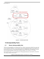
Interoperability Tests ..................................................... 90
5.1.
Device Interoperability Test ................................ 90
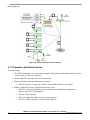
5.2.
Embedded Host Interoperability Test ................... 99
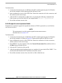
Auto PET tests ............................................................ 113
6.1.
Introduction of PET .......................................... 113
6.2.
Test environment .............................................. 113
6.3.
A-UUT tests ..................................................... 118
Useful links ................................................................. 122
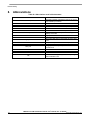
Abbreviations .............................................................. 124
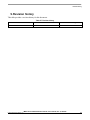
Revision history .......................................................... 125
Preparing for the test
2. Preparing for the test
This chapter lists all required materials for running the compliance test, including equipment,
documents, software and other necessary materials.
2.1.
Test boards
Tests were performed on the following boards:
MCIMX6SXSDB
MCIMX6SLEVK
MCIMX6QAICPU1
MCIMX6DLAICPU1
MCIMX6ULEVK
2.2.
Test environment
DUT OS: Linux 3.10.31_1.1.0_ GA
Test bed computer OS: WIN7
2.3.
Test equipment
The following tables list the test equipment and the tests for which they are required.
Keysight (Agilent) USB electrical test equipment was used in testing, however you may use equipment
from other vendors instead, such as Tektronix and Lecroy.
Table 1. Digital oscilloscope, software, and accessories
Test equipment
Tests
Part Number
Description
Manufacturer
N5416A
USB 2.0 automated
software
Keysight (Agilent)
DSO9254A
1169A
Digital real-time
oscilloscope
Differential probe amplifier
Embedded
Host highspeed
Device
Low/fullhigh-speed speed
1
1
1
1
1
1
Keysight (Agilent)
Keysight (Agilent)
1
1
—
1
1
—
Keysight (Agilent)
N5381A
Differential solder in probe
head
E2697A
N2774A
Single-ended probe
Current probe
Keysight (Agilent)
Keysight (Agilent)
—
—
—
—
3
1
HSEHET Board
High-speed Embedded
Host electrical test board
Allion
1
—
—
MQP
1
—
—
Keysight(Agilent)
1
1
1
Packet-Master USB- USB protocol and electrical
PET
tester
33401A
Digital multimeter
oequivalent.
i.MX 6 Series USB Certification Guide, User’s Guide, Rev. 0, 10/2015
2
Freescale Semiconductor, Inc.
Preparing for the test
Test equipment
Tests
Part Number
Description
Manufacturer
P40A-1P2J
DC5V Power Supply
SunPower
Embedded
Host highspeed
Device
Low/fullhigh-speed speed
1
1
1
Table 2. Test fixtures for the USB electrical test
Test fixture
Tests
Embedded
Host highspeed
Device
highspeed
Low/fullSpeed
Part number
Description
Manufacturer
E2649-66401
Device high-speed signal
quality test fixture
Keysight (Agilent)
—
1
—
Keysight (Agilent)
1
—
—
Keysight (Agilent)
—
—
1
Keysight (Agilent)
—
—
1
Keysight (Agilent)
1
—
—
Host high speed signal
quality test fixture
USB 2.0/3.0
Droop/Drop test fixture
USB inrush (SQiDD)
test fixture
E2649-66402
E2649-66405
E2646A/B
Receiver sensitivity test
fixture
E2649-66403
Table 3. Test fixtures for the USB electrical test
Required equipment
Part Number
Description
Tests
Manufacturer
Embedded
Host
high-speed
Device
Low/fullhigh-speed speed
81130A
82357A
8493C
Pulse/pattern generator
USB/GPIB interface
6 dB attenuators
Keysight (Agilent)
Keysight (Agilent)
Keysight (Agilent)
—
—
—
—
1
1
—
—
—
8120-4948 or
equivalent
50 ohm coaxial cable with
male SMA connectors at
both ends
Keysight (Agilent)
—
2
—
i.MX 6 Series USB Certification Guide, User's Guide, Rev. 0, 10/2015
Freescale Semiconductor, Inc.
3
Preparing for the test
Table 4. Miscellaneous cables and devices
Required equipment
Description
5 meter USB cable (any listed on USB-IF web site)
1.5 meter USB cable (any listed on USB-IF web site)
1 meter USB cable (any listed on USB-IF web site)
4 inch USB cable(any listed on USB-IF web site)
High-speed USB hub (any listed on USB-IF web site)
Full-speed USB hub (any listed on USB-IF web site)
High-speed USB device (any listed on USB-IF web site)
Full-speed USB device (any listed on USB-IF web site)
Low-speed USB device (any listed on USB-IF web site)
Tests
Embedded
Host highspeed
1
1
—
1
4
1
1
—
—
Device
Low/fullhigh-speed speed
1
—
—
1
—
—
1
—
—
6
—
1
1
4
1
—
1
1
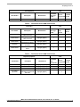
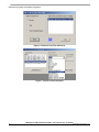
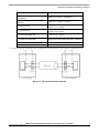
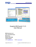
Figure 1. E2649 high-speed test fixture set
i.MX 6 Series USB Certification Guide, User’s Guide, Rev. 0, 10/2015
4
Freescale Semiconductor, Inc.
Preparing for the test
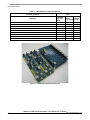
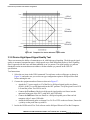
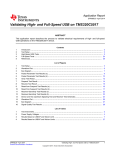
Figure 2. E2646A/B SQiDD test fixture
2.4.
Test software
The following table shows the software used for the USB Certification Test.
Table 5. Test software used for USB Certification Test
Name
Version
Description
USBET20
USBHSET
USB20CV
USB30CV
GraphicUSB
1.20
1.2.2.1
1.4.11.0
1.1.2.0
4.47
USB electrical analysis tool
Windows-based utility tool used to initiate test modes
USB 2.0 command verifier for USB 2.0 device framework testing
USB 3.0 command verifier for USB 3.0 device framework testing
Test software for PET test
2.5.
USB-IF required tests
Devices that support the features of USB OTG & EH V2.0 will undergo additional testing beyond the
tests described in this document. This additional testing is a subset of existing tests for USB peripherals
and USB host controllers.
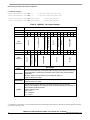
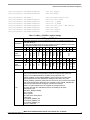
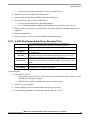
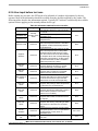
Table 6 describes which tests are required for full USB-IF certification by an EH with a Standard-A or
Micro-AB1 connector.
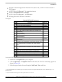
Table 7 describes which tests are required for full USB-IF certification by a device with a Micro-B
connector.
The following symbols are used in these tables:
A – Always required
* Required if feature is supported
** Required if there are multiple downstream ports
1
USB-IF allows Embedded Host to use the Micro-AB receptacle in 2012.
i.MX 6 Series USB Certification Guide, User's Guide, Rev. 0, 10/2015
Freescale Semiconductor, Inc.
5
Preparing for the test
Automated Test Ch6
Manual Test Ch7
Drop/Droop
DS LS SQT
DS FS SQT
DS HS Electrical
Table 6. Embedded Host test requirements for a Standard-A connector
High-speed Host
A
A
A/**
*
*
A
Full-speed Host
*
A
A/**
*
*
—
Low-speed Host
*
A
A/**
A
—
—
USB-IF test ►
USB speed ▼
Avg Current
1
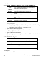
Automated Test Ch6
Manual Test Ch7
Back-Voltage
Inrush Current
US LS SQT
US FS SQT
US HS Electrical
Full-speed device
A
A
*
A
A
A
A
*
*
—
High-speed device
A
A
*
A
A
A
A
*
*
A
USB-IF test ►
USB speed ▼
USBCV
IOP Goldtree
Table 7. Device test requirements for a Micro-B connector
1
For the peripheral, if the silicon is only compliant with the general USB 2.0 specification, it is recognized as a standard USB2.0
peripheral. The automated test Ch6 must not be launched. If the silicon is compliant to the supplement of OTG and EH rev. 2.0 (with
OTG descriptor in the declaration), the device is recognized as a B-peripheral, and the automated test channel 6 must be launched.
i.MX 6 Series USB Certification Guide, User’s Guide, Rev. 0, 10/2015
6
Freescale Semiconductor, Inc.
Preparing for the test
2.6. Compliance checklist and TPL
Before sending the product and accessories to the certification lab, several checklists and TPLs must be
prepared. These documents include VID/PID (vendor/product information) 1, features, and accessories
your product supports. To get more information about these documents contact your certification lab.
The document templates can be downloaded from the USB-IF website:
http://www.usb.org/developers/compliance/check_list/
Checklist:
Compliance checklist for USB On-The-Go and Embedded Host Supplement revision 2.0
USB Compliance Checklist Peripheral Silicon (excluding hub silicon)
USB Compliance Checklist Peripherals (excluding hubs)
USB Compliance Checklist Systems
Target Peripheral List:
TPL Form for USB On-The-Go and Embedded Host Supplement revision 2.0
TPL Hub Form for USB On-The-Go and Embedded Host Supplement revision 2.0
2.7. Register the product in USB-IF
After you get the test reports from your certification lab, you need to submit your product to USB-IF for
registration to get the TID.
1. Check that your company is a member of USB-IF, register, and login to your account at
https://www.usb.org/members_landing.
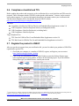
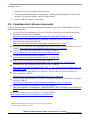
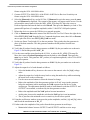
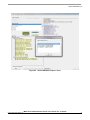
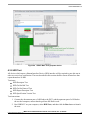
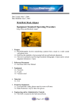
2. Click on My Account and then click on Add a Product to enter the Product Register page,
select a product type for your product, as shown in the following figure. If you do not know
what product type you should choose, consult your test lab.
Figure 3. USB product type
1
Use the VID of your company registered on USB-IF and not the VID of your USB silicon provider. The VID of the Freescale product on
USB-IF is 15A2 in hex or 5538 in decimal. You can download the whole Company List from the following website:
http://www.usb.org/developers/tools/comp_dump.
i.MX 6 Series USB Certification Guide, User's Guide, Rev. 0, 10/2015
Freescale Semiconductor, Inc.
7
Preparing for the test
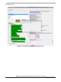
3. Select the Test Lab, for example Allion Labs, Inc.
4. Fill in the detailed information for your product, including the marketing name1, the revision,
checklists2, the product category, and the contact window.
5. Wait for USB-IF to approve your product.
2.8. Compliance test reference documents
To get to know the whole environment settings and detailed test steps of the USB Compliance Test, see
the following documents:
Universal Serial Bus Implementers Forum Full and Low Speed Electrical and Interoperability
Compliance Test Procedure (USB-IF)
http://www.usb.org/developers/compliance/electrical_tests/USB-IFTestProc1_3.pdf
USB On-The-Go and Embedded Host Automated Compliance Plan for the On-The-Go&
Embedded Host Supplement (USB-IF)
http://www.usb.org/developers/onthego/otgeh_compliance_plan_1_2.pdf
On-The-Go and Embedded Host Supplement to the USB, Revision 2.0, Specification Revision 2.0
(USB-IF) http://www.usb.org/developers/docs/usb20_docs/usb_20_0702115.zip
USB-IF USB 2.0 Certification Mandatory Test Matrix, (USB-IF)
http://compliance.usb.org/resources/usb2.0compliancetestprogram.pdf
Universal Serial Bus Specification (USB-IF)
http://www.usb.org/developers/docs/usb20_docs/usb_20_0702115.zip
USB-IF USB 2.0 Electrical Test Specification, (USB-IF)
http://www.usb.org/developers/compliance/USB-IF_USB_2_0_Electrical_Test_Spec081005.pdf
Embedded Host High Speed Electrical Test Procedure (USB-IF)
http://www.usb.org/developers/onthego/PIDVID_USB_2_0_High_Speed_Electrical_Embedded_Host_and
_OTG_MOI_1_0.pdf
Universal Serial Bus Implementers Forum Device Hi-Speed Electrical Test Procedure For
Agilent Infiniium (USB-IF)
http://www.usb.org/developers/compliance/Device_HS_Test_for_Agilent.pdf
Universal Serial Bus Implementers Forum Host Hi-Speed Electrical Test Procedure For Agilent
Infiniium (USB-IF)
http://www.usb.org/developers/compliance/electrical_tests/Host_HS_Test_for_Agilent.pdf
Agilent N5416A USB 2.0 Compliance Test Option (Agilent)
http://www.keysight.com/upload/cmc_upload/All/N5416A_USB2_Compliance_App_Testing_Not
es.pdf
Gold Suite Summary Test Procedure V1.35 Draft (USB-IF)
http://compliance.usb.org/resources/GoldSuiteTestProcedure.pdf
1
2
Make sure the marketing name is the same as the product name in checklists.
Save the checklists and TPLs in a zip file.
i.MX 6 Series USB Certification Guide, User’s Guide, Rev. 0, 10/2015
8
Freescale Semiconductor, Inc.
Preparing for the test
Allion HSEHET User Manual (Allion)
http://www.allion.com/TestTool/Allion-HSEHET-User-Manual.pdf
Universal Serial Bus Rev. 2.0 USB Command Verifier Compliance Test Specification (USB-IF)
http://www.usb.org/developers/tools/usb20_tools/#usb20cv
Universal Serial Bus Rev. 3.1 USB Command Verifier Compliance Test Specification (USB-IF)
http://www.usb.org/developers/tools/USB30CVSpec_1_4.pdf
Universal Serial Bus Mass Storage Class Compliance Test Specification (USB-IF)
http://www.usb.org/developers/docs/devclass_docs/Mass_Storage_Specification_Overview_v1.4_2-192010.pdf
i.MX 6Dual/6Quad Applications Processor Reference Manual (IMX6DQRM)
i.MX 6Solo/6DualLite Applications Processor Reference Manual (IMX6SDLRM)
i.MX 6SoloLite Applications Processor Reference Manual (IMX6SLRM)
i.MX 6SoloX Applications Processor Reference Manual (IMX6SXRM)
Configuring USB on i.MX 6 Series (AN4589)
i.MX 6 Series USB Certification Guide, User's Guide, Rev. 0, 10/2015
Freescale Semiconductor, Inc.
9
Electrical test procedure and software configuration
3.
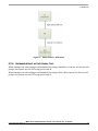
Electrical test procedure and software configuration
3.1. Software configuration for electrical test
Compared to a standard Linux/Android release, you may need to perform the software changes below to
implement the certification tests, it is applicable from the imx_3.10.31_1.1.0 Linux BSP GA release. For
the release previous to that, you may need to apply the related patches, and some examples may be
different for former releases, the user needs to change accordingly. See the detailed information in this
document: How to do USB Compliance Test for 3.10.y kernel, on the Freescale website:
https://community.freescale.com/docs/DOC-105609.
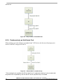
3.2. Legacy USB compliance tests
Upstream Full-Speed Signal Quality Test
Back-Voltage Test
Device Inrush Current Test
Downstream Full-Speed Signal Quality Test
Downstream Low-Speed Signal Quality Test
Host Drop Test
3.2.1. Upstream Full Speed Signal Quality Test 1
Test instructions:
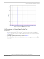
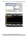
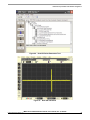
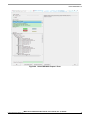
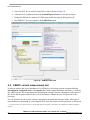
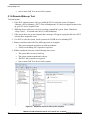
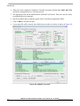
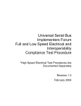
1. Select the test items in the USB Automated Test software on the oscilloscope as shown in
Figure 4. Make sure you set the test type configuration option to
Full-Speed Far End2 before running the test. Connect the equipment and test fixture as shown
in Figure 5.
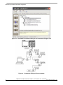
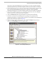
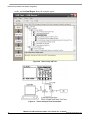
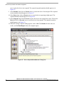
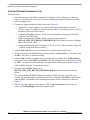
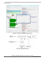
2. Select the HS electrical test tool software on the computer. Select the Device and click on the
Test button to enter the Device Test menu. See Figure 7.
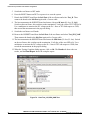
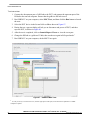
3. On the Device Test Menu of the HS Electrical Test Tool software, click on Enumerate Bus
once. All devices attached to the host controller should appear in the device enumeration list.
4. Highlight the device under test and select the Loop Device Descriptor from the Device
Command drop down menu. Click on Execute once. The VID of the Freescale product in
USB-IF is 15A2 in hex or 5538 in decimal.
1
2
i.MX 6 series processors are enumerated as a MSC device, low-speed upstream is not supported. Measure the upstream full
speed EYE without the 5 tier of hubs as this has no effect on the signal integrity
High-speed electrical tests are performed either near-end or far-end depending on the configuration of the product. The terms
near-end and far-end are based on which end of the cable the test fixture is attached in relation to the device being tested. All
HS peripherals with a B-receptacle are tested near-end (at the peripheral's receptacle). HS devices that have a captive cable are
tested far-end (at the end of the captive cable). Full-speed electrical tests are always performed far-end, the length of the cable
used in HS electrical tests is not important.
High-speed electrical tests of downstream ports on hosts and hubs are always performed near-end. For detailed explanation of
far-end and near-end in USB-IF compliance updates see: http://compliance.usb.org/index.asp?UpdateFile=Electrical#8.
i.MX 6 Series USB Certification Guide, User’s Guide, Rev. 0, 10/2015
10
Freescale Semiconductor, Inc.
Electrical test procedure and software configuration
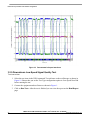
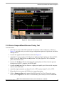
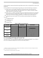
5. Click on Run Tests in the USB Automated Test software on the oscilloscope. After the test is
finished you can view the report on the Html Report page.
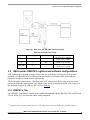
Figure 4. Automated Test software setting for the Upstream FS Signal Test
Figure 5. Upstream FS Signal Test environment
1
1
A full-speed hub here can force the downstream devices to operate in full-speed mode.
i.MX 6 Series USB Certification Guide, User's Guide, Rev. 0, 10/2015
Freescale Semiconductor, Inc.
11
Electrical test procedure and software configuration
Figure 6. Electrical Test Tool main menu
Figure 7. Device Control Command
i.MX 6 Series USB Certification Guide, User’s Guide, Rev. 0, 10/2015
12
Freescale Semiconductor, Inc.
Electrical test procedure and software configuration
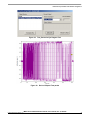
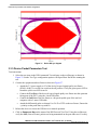
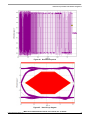
Figure 8. Upstream full-speed eye diagram
Figure 9. Upstream full-speed waveform
i.MX 6 Series USB Certification Guide, User's Guide, Rev. 0, 10/2015
Freescale Semiconductor, Inc.
13
Electrical test procedure and software configuration
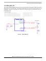
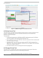
3.2.2. Back-Voltage Test
Test instructions:
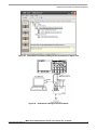
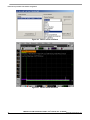
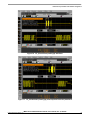
1. Select the test items in the USB Automated Test software on the oscilloscope as shown in
Figure 10.
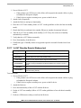
2. Connect the power supply to the DUT and connect the device upstream port to the backvoltage test fixture using a known good USB cable as shown in Figure 11. Measure and record
DC voltages on VBUS, D+ and D-. Voltages should all be less than or equal to 400 mV. Any
voltages greater than 400 mV will be recorded as a failure.
3. Plug the DUT into a known good host, and verify proper enumeration. Unplug the USB cable
from the host and reconnect the USB cable to the back-voltage test fixture. Measure and record
the DC voltages of VBUS, D+ and D-. All voltages must be less than or equal to 400 mV. Any
voltages greater than 400 mV will be recorded as a failure.
4. After the test is finished, you can view the report on the Html Report page.
Figure 10. Automated Test software setting for the Back-Voltage Test
i.MX 6 Series USB Certification Guide, User’s Guide, Rev. 0, 10/2015
14
Freescale Semiconductor, Inc.
Electrical test procedure and software configuration
Figure 11. Back-Voltage Test environment
Table 8. Back-Voltage Test record
Test point
DC voltage before
enumeration (mV)
DC voltage after
enumeration (mV)
Expected value (VDC)
VBUS
72
72
≤ 400 mV
D+
0
0
≤ 400 mV
D-
0
0
≤ 400 mV
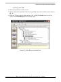
3.2.3. Device Inrush Current Test
The USB 2.0 specification enables a maximum capacity of 10 uF and therefore a maximum inrush of
50 uC. Note that it is required to have at least 1 uF of capacity in order to make ADP detection
possible. The DUT cannot consume more that 100 mA during the 100 ms starting up period. Inrush
current should be measured for a minimum of 100 ms after attachment.
Test instructions:
1. Connect the equipment and test fixture as shown in Figure 12. Use the current probe to capture
the VBUS current waveform. Ensure the probe direction is the same. When taking the
measurement, first calibrate the current probe to 0 mA. A current probe will produce a DC
offset that will result in an incorrect measurement if not performed beforehand.
2. Attach the DUT to the SQiDD board, then set the switch on the SQiDD board to the discharge
position (opposite the on position).
3. Disconnect the DUT from the SQiDD board, then set the switch on the SQiDD board to the on
position.
4. Adjust the oscilloscope settings to match the current test requirement: time base 50 ms/div,
Vertical resolution 500 mA/div, sample rate >1MS/s.
5. Re-connect the DUT to the SQiDD board in order to capture the inrush current waveform, then
save the waveform as a *.wfm or *.csv.
i.MX 6 Series USB Certification Guide, User's Guide, Rev. 0, 10/2015
Freescale Semiconductor, Inc.
15
Electrical test procedure and software configuration
6. Use the analysis software USBET20 on your computer to analyze the waveform file, then a
page will show the test result as shown in Figure 14. Inrush failures mostly occur when VBUS
and GND have too large a capacity between them.
Figure 12. Device Inrush Current Test environment
Figure 13. USBET20 operation interface
i.MX 6 Series USB Certification Guide, User’s Guide, Rev. 0, 10/2015
16
Freescale Semiconductor, Inc.
Electrical test procedure and software configuration
Figure 14. Device Inrush Current Test result
3.2.4. Downstream Full-Speed Signal Quality Test
Test instructions:
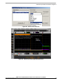
1. Select the test items in the USB Automated Test software on the oscilloscope as shown in
Figure 15. Make sure you set the test type configuration option to Full-Speed Far End before
running the test.
2. Connect the equipment and test fixture as shown in Figure 16.
3. Click on Run Tests. After the test is finished you can view the complete report on the Html
Report page.
i.MX 6 Series USB Certification Guide, User's Guide, Rev. 0, 10/2015
Freescale Semiconductor, Inc.
17
Electrical test procedure and software configuration
Figure 15. Automated Test software setting for the Downstream FS Signal Test
Figure 16. Downstream FS Signal Test environment
i.MX 6 Series USB Certification Guide, User’s Guide, Rev. 0, 10/2015
18
Freescale Semiconductor, Inc.
Electrical test procedure and software configuration
Figure 17. Downstream full-speed eye diagram
i.MX 6 Series USB Certification Guide, User's Guide, Rev. 0, 10/2015
Freescale Semiconductor, Inc.
19
Electrical test procedure and software configuration
Figure 18. Downstream full-speed waveform
3.2.5. Downstream Low-Speed Signal Quality Test
Test instructions:
1. Select the test items in the USB Automated Test software on the oscilloscope as shown in
Figure 19. Ensure that you set the Test Type configuration option to Low-Speed Near End
before running the test.
2. Connect the equipment and test fixture as shown in Figure 1.
3. Click on Run Tests. After the test is finished you can view the report on the Html Report
page.
i.MX 6 Series USB Certification Guide, User’s Guide, Rev. 0, 10/2015
20
Freescale Semiconductor, Inc.
Electrical test procedure and software configuration
Figure 19. Automated Test software setting for the Downstream LS Signal Test
Figure 20. Downstream LS Signal Test environment
i.MX 6 Series USB Certification Guide, User's Guide, Rev. 0, 10/2015
Freescale Semiconductor, Inc.
21
Electrical test procedure and software configuration
Figure 21. Downstream low-speed eye diagram
i.MX 6 Series USB Certification Guide, User’s Guide, Rev. 0, 10/2015
22
Freescale Semiconductor, Inc.
Electrical test procedure and software configuration
Figure 22. Downstream low-speed waveform
3.2.6. Host Drop and Droop tests
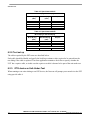
The Drop test is a measure of a host/hub’s ability to host full load current while keeping the output
voltage above specification. To perform this test, VBUS is measured with all downstream ports loaded
with 500 mA loads (for host and self-powered hubs). The lowest value measured across all ports must be
between 4.75 V and 5.5 V1 for host and self-powered hubs.
The Droop test is a transient test on adjacent ports. When a device is hot plugged into another port, the
droop in VBUS supplied to a port must be less than or equal to 330 mV for host, self-powered, and bus
powered hubs. This test is not needed there is only one host port on board.
Test instructions:
1. First, power the test fixture from your computer or a USB charger. The DS1 LED must
illuminate (green LED).
2. There are several switches/buttons used for general control of the test fixture. These include:
— Switch S5 enables you to select either the Droop or Drop test
1
USB-IF has published an ECN to increase the maximum voltage on VBUS from 5.25 V to 5.5 V in August 2014. The maximum voltage
is now 5.5 V.
i.MX 6 Series USB Certification Guide, User's Guide, Rev. 0, 10/2015
Freescale Semiconductor, Inc.
23
Electrical test procedure and software configuration
—
—
—
—
—
Switch S4 enables you to select either the 100 mA or 500 mA load
Press and hold S1 for at least three seconds to turn the test fixture on
While pressing and holding S2, press S1 to turn the test fixture off
When the fixture is on, pressing S2 will enable the left port
When the fixture is on, pressing S1 will enable the right port
3. Measure VBUS at the downstream USB connector with no cable or device inserted (no load),
then record it as VNL.
4. Measure VBUS at the downstream USB connector with 500 mA load, then record it as VLOADED.
Table 9. Host Drop Test Record
Item
Port01_Voltage
Expected value (VDC)
Vnon-load
5.19 V
4.75 V <= VBUS<= 5.5 V
VLoad
5.083 V
4.75 V <= VBUS<= 5.5 V
Vdrop
107 m V
≤ 750m V
Vdroop
—
≤ 330m V
NOTE
Keep the following items in mind while performing the drop test:
When taking the measurement take the cable resistance/voltage drop into
account as it can be significant when operating with high currents. For
example if you have 0.25 ohm resistance for cable and connectors and a
current of 500 mA you will have a voltage drop of 0.125 V. The
measurement must be performed as near to the A-Receptacle as possible
and if accessible you can measure at the A-receptacle VBUS/GND
soldering pad. The USB specifications define that the measurements
should be taken at the A-receptacle however as the A-receptacle is often
difficult to access you may use a fixture and a cable in between. Note that
these will give some additional voltage drop. Re-test the VBUS drop when
changing the power supply during testing.
i.MX 6 Series USB Certification Guide, User’s Guide, Rev. 0, 10/2015
24
Freescale Semiconductor, Inc.
Electrical test procedure and software configuration
Figure 23. Host Drop/Droop Test fixture
3.3. Device High-Speed Signal Test1
To perform the high-speed device test you must install the HS Electrical Test Tool software on your
computer, which can set the DUT to specific test patterns. To study the detailed description of the test
items in the Data Rate Test, see this document USB-IF USB 2.0 Electrical Test Specification. The
Device Receiver Sensitivity Test requires additional equipment, a digital signal generator (for example
Agilent 81130A) and related accessories.
Device High-Speed Signal Quality Test
— EL_2: Data Rate Test2
— EL_4, EL_5: Eye Pattern Test
— EL_6: Rise and Fall Time Test
— EL_7: Non-Monotonic Edge Test
Device Packet Parameters Test
— EL_21: Sync Field Length Test
— EL_25: EOP Length Test
— EL_22: Measure Inter-packet Gap Between First and Second Packets
— EL_22: Measure Inter-packet Gap Between Second and Third Packets
Device CHIRP Timing Test
— EL_28: Measure Device CHIRP-K Latency
— EL_29: Measure Device CHIRP-K Duration
— EL_31: Device Hi-Speed Terminations Enable and D+ Disconnect Time
1
For High Speed Device Test, need to install HS Electrical Test Tool software on Computer, which can set DUT into specific
test pattern.
2
To study the detailed description of the test items, see this document USB-IF USB 2.0 Electrical Test Specification.
i.MX 6 Series USB Certification Guide, User's Guide, Rev. 0, 10/2015
Freescale Semiconductor, Inc.
25
Electrical test procedure and software configuration
Device Suspend/Reset/Resume Timing Test
— EL_38, EL_39: Device Suspend Timing Response
— EL_40: Device Resume Timing Response
— EL_27: Device CHIRP Response to Reset from Hi-Speed Operation
— EL_28: Device CHIRP Response to Reset from Suspend
Device Test J/K, SE0_NAK Test
— EL_8: Device J Test
— EL_8: Device K Test
— EL_9: Device SE0_NAK Test
Device Receiver Sensitivity Test1
— EL_18: Minimum SYNC Field
— EL_17: Receiver Sensitivity Test
EL_16: Squelch
1
The Device Receiver Sensitivity Test requires additional equipment: digital signal generator (for example the Agilent 81130A) and
related accessories.
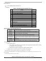
3.3.1. HS Device Electrical Test limits
The following table shows the Electrical Test limits for the HS device.
Table 10. HS Device Electrical Test limits
Test name
Pass limits
EL_2 Data Rate
Within 480 Mb/s +/-0.05%
EL_4 Eye Pattern (without captive cable)
Must meet template 1 transform waveform
requirements at TP3
EL_5 Eye Pattern (with captive cable)
Must meet template 2 transform waveform
requirements at TP2
EL_6 Device Rise/Fall Time
>500 ps
EL_7 Device Non-Monotonic Edge Test
Must have monotonic data transitions over the
vertical openings
EL_21 Device Sync Field Length Test
EL_25 Device EOP Length Test
32 bits, 65.62 ns <= VALUE <= 67.700 ns
8 bits, 15.600 ns <= VALUE <= 17.700 ns
EL_22 Measure Interpacket Gap Between
Second and Third Packets
16.640 ns <= VALUE <= 399.400 ns
EL_22 Measure Interpacket Gap Between
First and Second Packets
16.640 ns <= VALUE <= 399.400 ns
EL_28 Measure Device CHIRP-K Latency
EL_29 Measure Device CHIRP-K Duration
2.500 µs <= VALUE <= 6.000000 ms
1.000 ms <= VALUE <= 7.000 ms
EL_31 Device Hi-Speed Terminations Enable
and D+ Disconnect Time
1 ns <= VALUE <= 500.000 µs
EL_40 Device Resume Timing Response
Must transition back to high speed operation within
two bit times from the end of resume time signaling
EL_27 Device CHIRP Response to Reset
from Hi-Speed Operation
3.100 ms <= VALUE <= 6.000 ms
1
i.MX 6 Series USB Certification Guide, User’s Guide, Rev. 0, 10/2015
26
Freescale Semiconductor, Inc.
Electrical test procedure and software configuration
Test name
1.
Pass limits
EL_28 Device CHIRP Response to Reset
from Suspend
2.500 µs <= VALUE <= 6.000000 ms
EL_38 EL_39 Device Suspend Timing
Response
3.000 ms <= VALUE <= 3.125 ms
EL_8 Device J Test
360 mV <= D+ <= 440 mV
-10 mV <= D- <= 10 mV
EL_8 Device K Test
360 mV <= D- <= 440 mV
-10 mV <= D+ <= 10 mV
EL_9 Device SE0_NAK Test
-10 mV <= D+ <= 10 mV
-10 mV <= D- <= 10 mV
EL_18 Minimum SYNC Field
Detect the end of the SYNC field within 12 bit times
EL_17 Receiver sensitivity
EL_16 Squelch
VALUE <= +/- 200 mV
VALUE >= +/- 100 mV
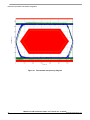
If the product used for certification only has a standard Micro B receptacle and no captive cable, EL_5 should not be used.
Figure 24. HS signal measurement planes
i.MX 6 Series USB Certification Guide, User's Guide, Rev. 0, 10/2015
Freescale Semiconductor, Inc.
27
Electrical test procedure and software configuration
Figure 25. Template 1 for device without a captive cable
3.3.2. Device High-Speed Signal Quality Test
These tests measure the ability of transmitters to do valid high-speed signaling. The high-speed signal
quality is measured on upstream ports. A high-speed scope with differential probes is used. Signaling
data is captured with the scope and then translated to an eye pattern. The signal quality eye patterns
obtained from the measurements must adhere with the transmit eye patterns in the USB 2.0
specification.
Test Instructions:
1. Select the test items in the USB Automated Test software on the oscilloscope as shown in
Figure 26, and make sure you set the test type configuration option to Hi-Speed Near End
before running the test.
2. Connect the equipment and test fixture as shown in Figure 27.
— Attach the 5 V power supply to J5 of the Device Hi-Speed signal quality test fixture
(E2649- 66401). Leave the test switch at the OFF position. Verify the green Power LED
is lit and the yellow Test LED is not lit.
— Connect the Test Port of the device high-speed signal quality test fixture into the
upstream facing port of the DUT, using the 4 inch USB cable.
— Connect the Init Port of the test fixture to a Hi-Speed capable port of the test bed
computer with a 5 meter USB cable.
— Attach the differential probe on channel 1 to D+/D- of TP2 on the test fixture, Ensure the
+ polarity on the probe lines up with D+.
3. Invoke the HS Electrical Test Tool software on the Hi-Speed Electrical Test Bed Computer.
i.MX 6 Series USB Certification Guide, User’s Guide, Rev. 0, 10/2015
28
Freescale Semiconductor, Inc.
Electrical test procedure and software configuration
Select Device and click the Test button to enter the Device Test menu. The DUT should be
enumerated with the device's VID shown together with the root port in which it is connected.
4. Select the HS Electrical Test Tool software on the hi-speed electrical test bed computer. Select
Device and click the Test button to enter the Device Test menu. The DUT should be
enumerated with the device's VID shown together with the root port in which it is connected.
5. Select TEST_PACKET from the Device Command drop down menu and click on Execute.
This forces the DUT to continuously transmit test packets.
6. Click on the Run Tests button of the Automated Test software on the oscilloscope.
7. Switch the Test Switch (S1) to the Test position according to the requirement of the
Automated Test Software. Verify the yellow test LED is lit. You should see the transmitted test
packet on the oscilloscope as shown in Figure 30.
8. When the Testing Complete dialog appears, click on Ok. The Results tab shows the test
results, and the Html Report shows the complete report.
Figure 26. Device HS Signal Quality Test
i.MX 6 Series USB Certification Guide, User's Guide, Rev. 0, 10/2015
Freescale Semiconductor, Inc.
29
Electrical test procedure and software configuration
Figure 27. Device Hi-Speed Signal Quality Test environment
Figure 28. Electrical Test Tool main menu
i.MX 6 Series USB Certification Guide, User’s Guide, Rev. 0, 10/2015
30
Freescale Semiconductor, Inc.
Electrical test procedure and software configuration
Figure 29. Test_Packet for Eye Diagram Test
Figure 30. Device Hi-Speed Test packet
i.MX 6 Series USB Certification Guide, User's Guide, Rev. 0, 10/2015
Freescale Semiconductor, Inc.
31
Electrical test procedure and software configuration
Figure 31. Device HS eye diagram
3.3.3. Device Packet Parameters Test
Test instructions:
1. Select the test items in the USB Automated Test software on the oscilloscope as shown in
Figure 32. Set the Test Type configuration option to Hi-Speed Near End before running the
test.
2. Connect the equipment and test fixture as shown in Figure 27.
— Attach the 5 V power supply to J5 of the device hi-speed signal quality test fixture
(E2649- 66401). Leave the test switch at the off position. Verify the green power LED is
lit and the yellow test LED is not lit.
— Connect the Test Port of the device hi-speed signal quality test fixture into the upstream
facing port of the DUT, using the 4 inch USB cable.
— Connect the Init Port of the test fixture to a hi-speed capable port of the test bed
computer with a 5 meter USB cable.
— Attach the differential probe on channel 1 to D+/D- of TP2 on the test fixture, Ensure the
+ polarity on the probe lines up with D+.
3. Reboot the device to restore the USB device to normal operation.
4. Click on Enumerate Bus on the menu of the HS Electrical Test Tool. Using the oscilloscope,
verify the SOF (Start of Frame) packets are being transmitted on the port under test. You may
i.MX 6 Series USB Certification Guide, User’s Guide, Rev. 0, 10/2015
32
Freescale Semiconductor, Inc.
Electrical test procedure and software configuration
need to lower the trigger level to below 400 mV.
5. Select the Single Step Set Feature from the Device Command window. Click on Execute
once. The oscilloscope will measure the sync field length (number of bits) of the third (from
device) packet (EL_21), EOP (End of Packet) width (number of bits) of the third packet
(EL_25), inter-packet gap between the second (from host) and the third (from device in
respond to the host’s) packets (EL_22), as shown in Figure 35 to Figure 37.
6. In the Device Test menu of the HS Electrical Test Tool, click on Step once more. This is the
second step of the two-step Single Step Set Feature command. The oscilloscope will measure
the inter-packet gap between the first (from host) and the second (from device in respond to the
host’s) packets (EL_22), as shown in Figure 39.
7. When the Testing Complete dialog appears, click on Ok. The Results tab shows the test
results, and the Html Report shows the complete report.
Figure 32. Device Hi-Speed Packet Parameters Test
i.MX 6 Series USB Certification Guide, User's Guide, Rev. 0, 10/2015
Freescale Semiconductor, Inc.
33
Electrical test procedure and software configuration
Figure 33. SOF waveform
Figure 34. Single Step Set Feature for Packet Parameters Test
i.MX 6 Series USB Certification Guide, User’s Guide, Rev. 0, 10/2015
34
Freescale Semiconductor, Inc.
Electrical test procedure and software configuration
Figure 35. EL_21 device sync field length waveform
Figure 36. EL_25 device EOP length waveform
i.MX 6 Series USB Certification Guide, User's Guide, Rev. 0, 10/2015
Freescale Semiconductor, Inc.
35
Electrical test procedure and software configuration
Figure 37. EL_22 device inter-packet gap (between second and third packets) waveform
Figure 38. Single Step Set Feature - second step
i.MX 6 Series USB Certification Guide, User’s Guide, Rev. 0, 10/2015
36
Freescale Semiconductor, Inc.
Electrical test procedure and software configuration
Figure 39. EL_22 Device inter-packet gap (between first and second packets) waveform
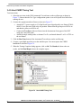
3.3.4. Device CHIRP Timing Test
Test instructions:
1. Select the test items in the USB Automated Test software on the oscilloscope as shown in
Figure 40, and make sure you set the Test Type configuration option to Hi-Speed Near End
before running the test.
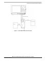
2. Connect the equipment and test fixture as shown in Figure 41.
3. Attach the 5 V power supply to J5 of the device hi-speed signal quality test fixture (E264966401). Leave the Test switch at the off position. Verify the green power LED is lit and the
yellow test LED is not lit.
4. Connect the Test Port of the device hi-speed signal quality test fixture into the upstream facing
port of the DUT, using the 4 inch USB cable.
5. Connect the Init Port of the test fixture to a hi-speed capable port of the test bed computer
with a 5 meter USB cable.
6. Attach the single end probes on channel 2 to D- of TP2, attach channel 3 to D+ of TP2.
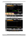
7. Reboot the device to restore the USB device to normal operation.
8. Click on Enumerate Bus on the menu of the HS Electrical Test Tool. The oscilloscope will
capture and measure the Chirp handshake as shown in Figure 42.
9. When the Testing Complete dialog appears, click on Ok. The Results tab shows the test
i.MX 6 Series USB Certification Guide, User's Guide, Rev. 0, 10/2015
Freescale Semiconductor, Inc.
37
Electrical test procedure and software configuration
results, and the Html Report shows the complete report.
Figure 40. Device Chirp J/K Test
Figure 41. Device Chirp J/K Test environment
i.MX 6 Series USB Certification Guide, User’s Guide, Rev. 0, 10/2015
38
Freescale Semiconductor, Inc.
Electrical test procedure and software configuration
Figure 42. Device CHIRP J/K waveform
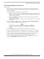
3.3.5. Device Suspend/Reset/Resume Timing Test
Test instructions:
1. Select the test items in the USB Automated Test software on the oscilloscope as shown in
Figure 43, and make sure you set the test type configuration option to hi-speed near end before
running the test.
2. Connect the equipment and test fixture as shown in Figure 41.
3. Attach the 5 V power supply to J5 of the device high-speed signal quality test fixture (E264966401). Leave the Test switch at the off position. Verify the grepower LED is lit and the
yellow Test LED is not lit.
4. Connect the Test Port of the device high-speed signal quality test fixture into the upstream
facing port of the DUT, using the 4 inch USB cable.
5. Connect the Init Port of the test fixture to a high-speed capable port of the test bed computer
with a 5 meter USB cable.
6. Attach the single end probes on channel 2 to D- of TP2, and on channel 3 to D+ of TP2.
7. Reboot the device to restore the USB device to normal operation.
8. Click on Enumerate Bus on the menu of the HS Electrical Test Tool. Choose the correct
device, select Suspend from the Device Command drop down menu, then click on Execute
i.MX 6 Series USB Certification Guide, User's Guide, Rev. 0, 10/2015
Freescale Semiconductor, Inc.
39
Electrical test procedure and software configuration
once to place the device into suspend. The captured suspend transition should appear as in
Figure 45.
9. Select Resume, then click on Execute once to resume the device from suspend. The captured
resume transition should appear as in Figure 47.
10. Select Reset, then click on Execute once to reset the device operating in high speed. The
captured transition should appear as in Figure 49.
11. Select Suspend, and click on Execute to place the device into suspend once more. Then select
Reset and click on Execute once to reset the device from suspend. The captured transition
should appear as in Figure 50.
12. When the Testing Complete dialog appears, click on Ok. The Results tab shows the test
results, and the Html Report shows the complete report.
Figure 43. Device Suspend/Reset/Resume Timing Test
i.MX 6 Series USB Certification Guide, User’s Guide, Rev. 0, 10/2015
40
Freescale Semiconductor, Inc.
Electrical test procedure and software configuration
Figure 44. Device suspend command
Figure 45. Device suspend waveform
i.MX 6 Series USB Certification Guide, User's Guide, Rev. 0, 10/2015
Freescale Semiconductor, Inc.
41
Electrical test procedure and software configuration
Figure 46. Device resume command
Figure 47. Device resume waveform
i.MX 6 Series USB Certification Guide, User’s Guide, Rev. 0, 10/2015
42
Freescale Semiconductor, Inc.
Electrical test procedure and software configuration
Figure 48. Device reset command
Figure 49. Device reset from high-speed waveform
i.MX 6 Series USB Certification Guide, User's Guide, Rev. 0, 10/2015
Freescale Semiconductor, Inc.
43
Electrical test procedure and software configuration
Figure 50. Device reset from suspend waveform
3.3.6. Device Test J/K, SE0_NAK Test
Test instructions:
1. Select the test items in the USB Automated Test software on the oscilloscope as shown in
Figure 51.
2. Connect the equipment and test fixture as shown in Figure 52.
— Attach the 5 V power supply to J5 of the device high-speed signal quality test fixture
(E2649- 66401). Leave the Test switch at the off position. Verify the green power LED is
lit and the yellow test LED is not lit.
— Connect the Test Port of the device high-speed signal quality test fixture into the
upstream facing port of the DUT, using the 4 inch USB cable.
— Connect the Init Port of the test fixture to a high-speed capable port of the test bed
computer with a 5 m USB cable.
— Attach the single end probes on channel 2 to D- of TP2, and on channel 3 to D+ of TP2.
3. Reboot the device to restore the USB device to normal operation.
4. Click on Enumerate Bus on the menu of the HS Electrical Test Tool. Choose the correct
device. Select TEST_J from the Device Command drop down menu, then click on Execute
once to place the device into TEST_J test mode.
5. Switch the test fixture into the test position. Use a multimeter to measure the DC voltage on the
D+/- lines at TP2 with respect to GND, then record the measurement in the pop out dialog.
i.MX 6 Series USB Certification Guide, User’s Guide, Rev. 0, 10/2015
44
Freescale Semiconductor, Inc.
Electrical test procedure and software configuration
6. Reboot the device to restore the USB device to normal operation.
7. Click on Enumerate Bus on the menu of the HS Electrical Test Tool. Choose the correct
device, Select TEST_K from the Device Command drop down menu, then click on EXECUTE
once to place the device into TEST_K test mode.
8. Switch the test fixture into the test position. Use a multimeter to measure the DC voltage on
the D+/- lines at TP2 with respect to GND, then record the measurement in the pop out dialog.
9. Reboot the device to restore the USB device to normal operation.
10. Click on Enumerate Bus on the menu of the HS Electrical Test Tool. Choose the correct
device, Select TEST_SE0_NAK from the Device Command drop down menu, then click on
exectute once to place the device into TEST_SE0_NAK test mode.
11. Switch the test fixture to the test position. Use a multimeter to measure the DC voltage on the
D+/- lines at TP2 with respect to GND, then record the measurement in the pop out dialog.
12. When the Testing Complete dialog appears, click on Ok. The Results tab shows the test
results, and the Html Report shows the complete report.
Figure 51. Device Test_J/K, SE0_NAK Test
i.MX 6 Series USB Certification Guide, User's Guide, Rev. 0, 10/2015
Freescale Semiconductor, Inc.
45
Electrical test procedure and software configuration
Figure 52. Device Test_J/K, SE0_NAK Test environment
Figure 53. Device Test_J command
Table 11. Host Drop Test record
Test Mode
D+ Voltage(mV)
D- Voltage(mV)
J
415
4
K
4
417
SE0_NAK
1
1
Expected value
360 mV <= D+ <= 440 mV
-10 mV <= D- <= 10 mV
360 mV <= D- <= 440 mV
-10 mV <= D+ <= 10 mV
-10 mV <= D+ <= 10 mV
-10 mV <= D- <= 10 mV
3.3.7. Device Receiver Sensitivity Test
Receiver sensitivity and squelch measurements are to be made at the upstream port pins as defined in the
USB 2.0 Specification.
i.MX 6 Series USB Certification Guide, User’s Guide, Rev. 0, 10/2015
46
Freescale Semiconductor, Inc.
Electrical test procedure and software configuration
The Transmission Envelope Detector of a A high-speed capable device must be fast enough to enable
the HS receiver to detect data transmission, achieve DLL lock, and detect the end of the SYNC field
within 12 bit times. When all packets are NAK by the device this test (EL_18) is considered to have
passed.
In Section 7.1.7.2 of USB2.0 Spec it requires squelch (EL_16) to occur below 100 mV magnitude.
Therefore no packets must be acknowledged between -100 mV and +100 mV. Full squelch may occur at
higher voltages, but it is mandatory between -100 mV and +100 mV.
Receiver sensitivity requires all packets to be reliably received down to 150 mV magnitude. Packets
may be received at lower voltages, but it is mandatory for all packets to be received at levels above
150 mV magnitude. This measurement is to be made at the upstream pins but the test fixture does not
allow this. The USB-IF requires packets to be reliably received at levels above 200 mV (50 mV waiver
to compensate for the voltage drop) for EL_17. Packets can, but do not need to be, received between
-200 mV and +200 mV.
For a detailed explanation of device receiver sensitivity, see the following:
http://compliance.usb.org/index.asp?UpdateFile=Electrical&Format=Standard#3
Figure 54. Device sensitivity detection envelope
Test instructions:
1. Select the test items in the USB Automated Test software on the oscilloscope as shown in
Figure 55, and ensure sure the Test Type configuration option is set to Hi-Speed Near End
before running the test.
2. Connect the equipment and test fixture as shown in Figure 56.
— Attach the 5 V power supply to J5 of the Device Hi-Speed signal quality test fixture
(E2649- 66401). Leave the test switch at the off position. Verify the green power LED is
lit and the yellow test LED is not lit.
— Connect the Test Port of the device hi-speed signal quality test fixture into the upstream
facing port of the DUT, using the 4 inch USB cable.
— Connect the Init Port of the test fixture to a high-speed capable port of the test bed
computer with a 5 meter USB cable.
— Attach the differential probe on channel 1 to D+/D- of TP2 on the test fixture, Ensure the
+ polarity on the probe lines up with D+.
3. Connect the 81130A pulse generator to the oscilloscope using the 82357A USB/GPIB
Interface.
— If you choose to use the Agilent 81130A Pulse/Pattern Generator, connect the 8493C 6
dB attenuators to OUTPUT1 and OUTPUT2 of Agilent 81130A Pulse/Pattern Generator.
4. Connect OUTPUT1 to SMA1 (D+) of the E2649- 66403 Device Receiver Sensitivity test
i.MX 6 Series USB Certification Guide, User's Guide, Rev. 0, 10/2015
Freescale Semiconductor, Inc.
47
Electrical test procedure and software configuration
fixture using the 8120- 4948 SMA cables.
5. Connect OUTPUT2 to SMA2 (D-) of the E2649- 66403 Device Receiver Sensitivity test
fixture using the 8120- 4948 SMA cables.
6. Select the Memcard soft key on the 81130A,. If Memcard is not in the menu, press the more
key until Memcard is displayed. The content of the memory will appear on the screen. Use the
cursor and the rotary knob to select the MIN_ADD1.ST0 setup file. Move the cursor to
Perform Operation and turn the knob to select Recall. Then press the Enter key to load it. This
generates IN packets (of compliant amplitude) with a 12-bit SYNC field packet pattern.
7. Reboot the device to restore the USB device to normal operation.
8. Click on Enumerate Bus on the menu of the HS Electrical Test Tool. Choose the right device,
Select TEST_SE0_NAK from the Device Command drop down menu, then click on Execute
once to place the device into TEST_SE0_NAK test mode.
9. Set the test fixture Test Switch (S1) to the test position. This switches the data generator in
place of the host controller. The data generator emulates the IN packets from the host
controller.
10. Verify that all packets from the data generator are NAK’d by the port under test as shown in
Figure 58. Record the pass/fail in EL_18.
11. Use the cursor and the rotary knob on the 81130A, to select the IN_ADD1.ST0 setup file.
Move the cursor to Perform Operation and turn the knob to select Recall. Then press the
enter key to load it. This generates “IN” packets (of compliant amplitude) with a 32-bit SYNC
field packet pattern.
12. Verify that all packets from the data generator are NAK’d by the port under test as shown in
Figure 59.
13. Adjust the output level of each channel as follows:
— Select the levels soft key, then move the cursor to the numeric value for [high] voltage
value.
— Adjust the output level with the rotary knob or using the number keys while monitoring
the actual level on the oscilloscope.
— Use the cursor arrow buttons to select the channel to change.
— Reduce the amplitude of the data generator packets in 20 mV steps (on the generator
before the attenuator) while monitoring the NAK response from the device on the
oscilloscope. The adjustment should be made to both channels such that OUTPUT1 and
OUTPUT2 are matched, as indicated by the data generator readout.
— Reduce the amplitude until the NAK packets become intermittent.
— At this point, increase the amplitude such that the NAK packet is not intermittent.
— This is just above the minimum receiver sensitivity levels before squelch.
14. Using the oscilloscope markers to measure the packet amplitude, read the [Ay] and [By] values
and record the measurement in EL_17.
15. Further reduce the amplitude of the packet from the data generator in small steps.
— Maintain the balance between OUTPUT1 and OUTPUT2 until the receiver stops
i.MX 6 Series USB Certification Guide, User’s Guide, Rev. 0, 10/2015
48
Freescale Semiconductor, Inc.
Electrical test procedure and software configuration
responding with a NAK.
16. This is the squelch level of the receiver.
17. Measure the packet amplitude. Read the [Ay] and [By] values and record the measurement in
EL_16.
18. When the Testing Complete dialog appears, click on Ok. The Results tab shows the test
results, and the Html Report shows the whole report.
Figure 55. Device Receiver Sensitivity Test
i.MX 6 Series USB Certification Guide, User's Guide, Rev. 0, 10/2015
Freescale Semiconductor, Inc.
49
Electrical test procedure and software configuration
Figure 56. Device Receiver Sensitivity Test environment
Figure 57. Device Test_SE0_NAK command
i.MX 6 Series USB Certification Guide, User’s Guide, Rev. 0, 10/2015
50
Freescale Semiconductor, Inc.
Electrical test procedure and software configuration
Figure 58. Receiver respond with NAK to IN from data generator
Figure 59. Measuring the packet amplitude
i.MX 6 Series USB Certification Guide, User's Guide, Rev. 0, 10/2015
Freescale Semiconductor, Inc.
51
Electrical test procedure and software configuration
3.4. Host High-Speed Signal Test
Host High-Speed Signal Quality Test
— EL_2: Data Rate Test
— EL_3: Eye Pattern and Mask Test
— EL_6: Rise and Fall Time Test
— EL_7: Non-Monotonic Edge Test
Host Packet Parameters Test
— EL_21: Sync Field Length Test
— EL_25: EOP Length Test
— EL_23: Inter-packet Gap Between First 2 Packets Test
— EL_22: Measure Inter-packet Gap Between Host And Device Packet Test
— EL_55: SOF EOP Width Test
Host CHIRP Timing Test
— EL_33: Measure Host CHIRP response time
— EL_34: Measure Host CHIRP-J/K duration
Host Suspend/Resume Timing Test
— EL_39: Host Suspend Timing Response
— EL_41: Host Resume Timing Response
Host Test J/K, SE0_NAK Test
— EL_8: Host J Test
— EL_8: Host K Test
— EL_9: Host SE0_NAK Test
3.4.1. HS host electrical test limits
Table 12. HS host Electrical Test limits
Test name
Pass limits
EL_2 Data rate
Within 480 Mb/s +/-0.05%
EL_3 Data Eye and Mask Test
Must meet Template 1 transform waveform
requirements at TP2
EL_6 Host rise/fall time
>500 ps
EL_7 Host Non-Monotonic Edge Test
Must have monotonic data transitions over the
vertical openings
EL_21 Sync Field Length Test
EL_25 EOP Length Test
32 bits, 65.62 ns <= VALUE <= 67.700 ns
8 bits, 15.620 ns <= VALUE <= 17.700 ns
EL_23 Inter-packet gap between first 2
Packets Test
183.000 ns <= VALUE <= 399.400 ns
EL_55 SOF EOP Width Test
40 bits, 81.100 ns <= VALUE <= 83.388 ns
EL_22 Inter-packet gap between Host and
Device Packet Test
16.640 ns <= VALUE <= 399.90 ns
EL_33 CHIRP timing response
EL_34 CHIRP J/K width
1 ns <= VALUE <= 100.000 µs
40.000 µs <= VALUE <= 60.000 µs
i.MX 6 Series USB Certification Guide, User’s Guide, Rev. 0, 10/2015
52
Freescale Semiconductor, Inc.
Electrical test procedure and software configuration
EL_35 SOF Timing Response
EL_39 Suspend Timing Response
EL_41 Resume Timing Response
100.000 µs <= VALUE <= 500.000 µs
3.000 ms <= VALUE <= 3.125 ms
VALUE <= 3.000 ms
EL_8 Host J Test
360 mV <= D+ <= 440 mV
-10mV <= D- <= 10 mV
EL_8 Host K Test
360 mV <= D- <= 440 mV
-10 mV <= D+ <= 10 mV
EL_9 Host SE0_NAK Test
-10 mV <= D+ <= 10 mV
-10 mV <= D- <= 10 mV
3.4.2. Test method and tool
In USB Certification, the host is a product based on Windows x86 or x64 systems, which can implement
the HS Electrical Test Tool to run the Host test. An Embedded Host is a product based on Linux,
Android, or other RTOS. USB-IF defines a method of entering the specified test modes via PID/VID
detection. See chapter 6.4.1 of On-The-Go and Embedded Host Supplement to the USB specification for
further information.
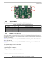
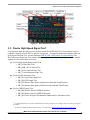
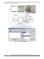
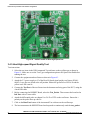
The certification lab provides an HSEHET Board to perform the Host or Embedded Host test. This
board can be set to different PIDs, as shown in Figure 60.
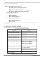
Table 13. Test modes product ID definitions
PID
0x0101
0x0102
0x0103
0x0104
0x0105
0x0106
0x0107
0x0108
Test Mode
Test_SE0_NAK
Test_J
Test_K
Test_Packet
Reserved
HS_HOST_PORT_SUSPEND_RESUME
SINGLE_STEP_GET_DEV_DESC
SINGLE_STEP_ GET_DEV_DESC_DATA
i.MX 6 Series USB Certification Guide, User's Guide, Rev. 0, 10/2015
Freescale Semiconductor, Inc.
53
Electrical test procedure and software configuration
Figure 60. HSEHET board for Host High-Speed Test
3.4.3. Host High-speed Signal Quality Test
Test instructions:
1. Select the test items in the USB Automated Test software on the oscilloscope as shown in
Figure 61. Make sure to set the Test Type configuration option to Hi-Speed Near End before
running the test.
2. Connect the equipment and test fixture as shown in Figure 63.
3. Attach the 5 V power supply to J5 of the Host Hi-Speed signal quality test fixture (E264966402). Leave the test switch at the off position. Ensure the green Power LED is lit and the
yellow test LED is not lit.
4. Connect the Test Port of the test fixture into the downstream facing port of the DUT, using the
4 inch USB cable.
5. Before connecting the HSEHET Board, select the Test_Packet. Then connect the board to the
Init Port with a 5 meter cable.
6. Attach the differential probe on channel 1 to D+/D- of TP2 on the test fixture. Ensure the +
polarity on the probe lines up with D+.
7. Click on the Run Tests button of the Automated Test software on the oscilloscope.
8. The host enumerates the HSEHET board and responds to continuously send the test_packet.
i.MX 6 Series USB Certification Guide, User’s Guide, Rev. 0, 10/2015
54
Freescale Semiconductor, Inc.
Electrical test procedure and software configuration
Switch the test fixture to switch the termination on. Ensure the yellow test LED is lit.
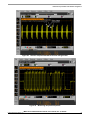
9. You should see the transmitted test packet on the oscilloscope as shown in Figure 64.
10. When the Testing Complete dialog appears, click on Ok. The Results tab shows the test
results, and the Html Report shows the complete report.
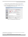
Figure 61. Select Embedded Host for HS Electrical Test1
1
Select Embedded Host for non-Windows products. Click on the Connection Option button here to select a differential or
single-end probe if you are using the latest software.
i.MX 6 Series USB Certification Guide, User's Guide, Rev. 0, 10/2015
Freescale Semiconductor, Inc.
55
Electrical test procedure and software configuration
Figure 62. Host HS Signal Quality test
Figure 63. Host HS Signal Quality Test environment
i.MX 6 Series USB Certification Guide, User’s Guide, Rev. 0, 10/2015
56
Freescale Semiconductor, Inc.
Electrical test procedure and software configuration
Figure 64. Host HS test packet
Figure 65. Host HS eye diagram
i.MX 6 Series USB Certification Guide, User's Guide, Rev. 0, 10/2015
Freescale Semiconductor, Inc.
57
Electrical test procedure and software configuration
3.4.4. Host Packet Parameters Test
Test instructions:
1. Select the test items in the USB Automated Test software on the oscilloscope as shown in
Figure 66, and make sure you set the Test Type configuration option to Hi-Speed Near End
before running the test.
2. Connect the equipment and test fixture as shown in Figure 63.
— Attach the 5 V power supply to J5 of the Host Hi-Speed signal quality test fixture
(E2649- 66402). Leave the test switch at the off position. Verify the green power LED is
lit and the yellow test LED is not lit.
— Connect the Test Port of the test fixture into the downstream facing port of the DUT,
using the 4 inch USB cable.
— Before connecting the HSEHET Board, select its correct position at
SINGLE_STEP_GET_DEVICE_DESCRIPTOR. Then connect the board to the Init
Port with a 5 meter cable.
— Attach the differential probe on channel 1 to D+/D- of TP2 on the test fixture. Ensure the
+ polarity on the probe lines up with D+.
3. Click the Run Tests button of the Automated Test software on the oscilloscope.
4. The host enumerates the HSEHET board and responds by sending SOFs for 15 seconds. Click
on OK to close the Test Instruction dialog.
5. After the SOFs sending is complete the host initiates the setup phase of the GetDescriptor()
command. The host sends SETUP and DATA (first and second packet), then the device sends
an ACK. You should see the transmitted test packet on the oscilloscope as shown in Figure 70.
Click on OK to close the Test Instruction dialog.
6. Disconnect the HSEHET Board, select
SINGLE_STEP_GET_DEVICE_DESCRIPTOR_DATA, then reconnect it to the test
fixture.
7. The host enumerates the HSEHET board and requests GetDescriptor(), then waits for 15
seconds. The host then initiates an IN token, the device responds with a DATA, then the host
sends an ACK. You should see the transmitted test packet on the oscilloscope as shown in
Figure 71.
8. When the Testing Complete dialog appears, click on Ok. The Results tab shows the test
results, and the Html Report shows the complete report.
i.MX 6 Series USB Certification Guide, User’s Guide, Rev. 0, 10/2015
58
Freescale Semiconductor, Inc.
Electrical test procedure and software configuration
Figure 66. Host HS Packet Parameters Test
Figure 67. Host SOF waveform
i.MX 6 Series USB Certification Guide, User's Guide, Rev. 0, 10/2015
Freescale Semiconductor, Inc.
59
Electrical test procedure and software configuration
Figure 68. EL_21 host sync field length waveform
Figure 69. EL_25 host EOP length waveform
i.MX 6 Series USB Certification Guide, User’s Guide, Rev. 0, 10/2015
60
Freescale Semiconductor, Inc.
Electrical test procedure and software configuration
Figure 70. EL_23 host inter-packet gap waveform
Figure 71. EL_22 Host Inter-packet gap (host response to device) waveform
i.MX 6 Series USB Certification Guide, User's Guide, Rev. 0, 10/2015
Freescale Semiconductor, Inc.
61
Electrical test procedure and software configuration
3.4.5. Host CHIRP Timing Test
Test instructions:
1. Select the test items in the USB Automated Test software on the oscilloscope as shown in
Figure 72. Ensure that the Test Type configuration option is set to Hi-Speed Near End before
running the test.
2. Connect the equipment and test fixture as shown in Figure 73.
— Attach the 5 V power supply to J5 of the Host hi-speed signal quality test fixture (E264966402). Leave the test switch at the off position. Ensure that the green power LED is on
and that the yellow test LED is off.
— Connect the Test Port of the test fixture into the downstream facing port of the DUT
using the 4 inch USB cable.
— Attach the single-ended probes on channel 2 to D-, and attach channel 3 to D+ of TP2 on
the test fixture.
3. Click the Run Tests button of the Automated Test software on the oscilloscope.
4. Connect a good high-speed device to the initialize port. You must capture the CHIRP
handshake as shown in Figure 74.
5. When the Testing Complete dialog appears, click on Ok. The Results tab shows the test
results, and the Html Report shows the complete report.
Figure 72. Host CHIRP Timing Test
i.MX 6 Series USB Certification Guide, User’s Guide, Rev. 0, 10/2015
62
Freescale Semiconductor, Inc.
Electrical test procedure and software configuration
Figure 73. Host CHIRP Timing Test environment
i.MX 6 Series USB Certification Guide, User's Guide, Rev. 0, 10/2015
Freescale Semiconductor, Inc.
63
Electrical test procedure and software configuration
Figure 74. Host CHIRP J/K waveform
Figure 75. Time between SOF and last chirp-J/K
i.MX 6 Series USB Certification Guide, User’s Guide, Rev. 0, 10/2015
64
Freescale Semiconductor, Inc.
Electrical test procedure and software configuration
3.4.6. Host Suspend/Resume Timing Test
Test instructions:
1. Select the test items in the USB Automated Test software on the oscilloscope as shown in
Figure 76, and ensure that the Test Type configuration option is set to Hi-Speed Near End
before running the test.
2. Connect the equipment and test fixture as shown in Figure 73.
— Attach the 5 V power supply to J5 of the Host hi-speed signal quality test fixture (E264966402). Leave the test switch at the off position. Ensure that the green power LED is on
and the yellow test LED is off.
— Connect the Test Port of the test fixture into the downstream facing port of the DUT
using the 4 inch USB cable.
— Attach the single-ended probes on channel 2 to D-, and attach channel 3 to D+ of TP2 on
the test fixture.
3. Before connecting the HSEHET Board select HS_HOST_PORT_SUSPEND_RESUME.
Connect the board to the Init Port with a 5 meter cable.
NOTE
The HSEHET board should be attached before clicking on the Run Tests
button, in case that you capture the Bus Enumeration instead of Suspend
transition.
4. Click the Run Tests button of the Automated Test software on the oscilloscope.
5. After 15 seconds the host port will enter Suspend state, as shown in Figure 77. The captured
transition should be as shown in Figure 77. Click on OK to close the Test Instruction dialog.
6. After 15 seconds of suspend state the host shall issue a Resume K state on the bus, then
continue sending SOFs. The captured transition should be as shown in Figure 78.
7. When the Testing Complete dialog appears, click on Ok. The Results tab shows the test
results, and the Html Report shows the complete report.
i.MX 6 Series USB Certification Guide, User's Guide, Rev. 0, 10/2015
Freescale Semiconductor, Inc.
65
Electrical test procedure and software configuration
Figure 76. Host Suspend/Resume Timing Test
Figure 77. EL_39 host suspend waveform
i.MX 6 Series USB Certification Guide, User’s Guide, Rev. 0, 10/2015
66
Freescale Semiconductor, Inc.
Electrical test procedure and software configuration
Figure 78. EL_41 host resume waveform
3.4.7. Host test J/K, SE0_NAK Test
Test instructions:
1. Select the test items in the USB Automated Test software on the oscilloscope as shown in
Figure 79 and make sure you set the Test Type configuration option to Hi-Speed Near End
before running the test.
2. Connect the equipment and test fixture as shown in Figure 80.
— Attach the 5V power supply to J5 of the Host Hi-Speed signal quality test fixture (E264966402). Leave the test switch at the off position. Verify the green power LED is lit and
the yellow test LED is not lit.
— Connect the Test Port of the test fixture into the downstream facing port of the DUT,
using the 4 inch USB cable.
— Before connecting the HSEHET Board, put it in the right position by selecting Test_J.
Then connect the board to the Init Port with a 5m cable.
— Attach the single-ended probes on channel 2 to D-, channel 3 to D+ of TP2 on the test
fixture.
3. Click on the Run Tests button of Automated Test Software on the oscilloscope.
4. The host enumerates the HSEHET board and enters a hi-speed J state (D+ high; D- low).
Switch on the test fixture, this switches the termination on. Verify the yellow TEST LED is lit.
Use a multimeter to measure the DC voltage on the D+/- lines at TP2 with respect to GND,
then record the measurement in the pop out dialog.
i.MX 6 Series USB Certification Guide, User's Guide, Rev. 0, 10/2015
Freescale Semiconductor, Inc.
67
Electrical test procedure and software configuration
5. Switch the test fixture to OFF mode.
6. Press the RESET button on DUT or repower it to reset the system.
7. Detach the HSEHET board from the Init Port of the test fixture and select Test_K. Then
connect the board to the Init Port again with a 5 meter cable.
8. The host enumerates the HSEHET board and enters a hi-speed K state (D+ low; D- high).
Switch on the test fixture, this switches on the termination. Verify the yellow TEST LED is lit.
Use a multimeter to measure the DC voltage on the D+/- lines at TP2 with respect to GND,
then record the measurement in the pop out dialog.
9. Switch the test fixture to off mode.
10. Remove the HSEHET board from the Init Port of the test fixture and select Test_SE0_NAK.
Then connect the board to the Init Port again with a 5 meter cable.
11. The host enumerates the HSEHET board and enters the SE0 State (D+ low; D- low). Switch
on the test fixture, this switches on the termination. Verify the yellow test LED is lit. Use a
multimeter to measure the DC voltage on the D+/- lines at TP2 with respect to GND, then
record the measurement in the pop out dialog.
12. When the Testing Complete dialog appears, click on Ok. The Results tab shows the test
results, and the Html Report shows the complete report.
Figure 79. Host Test_J/K, SE0_NAK Test
i.MX 6 Series USB Certification Guide, User’s Guide, Rev. 0, 10/2015
68
Freescale Semiconductor, Inc.
Electrical test procedure and software configuration
Figure 80. Host Test_J/K, SE0_NAK Test environment
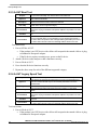
Table 14. Host Drop Test record
Test mode
D+ Voltage(mV)
D- Voltage(mV)
J
400
4
K
4
400
SE0_NAK
1
1
Expected value
360 mV <= D+ <= 440 mV
-10 mV <= D- <= 10 mV
360 mV <= D- <= 440 mV
-10 mV <= D+ <= 10 mV
-10 mV <= D+ <= 10 mV
-10 mV <= D- <= 10 mV
3.5. i.MX 6 series USB PHY registers and software configurations
USB signal integrity depends on many factors, such as circuit design, PCB layout, stack-up, and
impedance. Each product may be different from one another, so customers need to fine-tune the
parameters in order to obtain the best signal quality.
The test board has routed out two USB Ports: one OTG1, and one host. Each of the ports has several
registers to adjust the signal voltage level and slew rate. See the detailed description of the registers in
the document Configuring USB on i.MX 6 Series (AN4589).
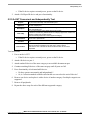
3.5.1. USBPHYx_TXn
The USB PHY Transmitter Control Register handles the transmit controls. Bit fields TXCAL45DP and
TXCAL45DM, D_CAL adjust the output voltage amplitude.
1
The software does not support full feature OTG, this port is usually used as a device or Embedded Host, selected by USB_ID.
i.MX 6 Series USB Certification Guide, User's Guide, Rev. 0, 10/2015
Freescale Semiconductor, Inc.
69
Electrical test procedure and software configuration
Command samples:
/unit_tests/memtool 0x20c9010 1
/unit_tests/memtool 0x20cA010 1
// OTG Port Read register data
// Host Port Read register data
1
/unit_tests/memtool 0x20c9010=0x1c060607
//write OTG_PHY_TX
/unit_tests/memtool 0x20cA010=0x1c060607
//write HOST_PHY_TX
Table 15. USBPHYx_TXn register settings
Name
29
28
27
26
25
24
23
22
21
20
19
18
17
16
0
0
1
0
0
0
0
0
0
0
0
0
1
1
0
TX_SYNC_INVERT
TX_SYNC_MUX
TXENCAL45DP
RSVD3
Bit #
15
14
13
12
11
10
9
8
7
6
5
4
3
2
1
0
Reset value
0
0
0
0
0
1
1
0
0
0
0
0
0
1
1
1
D_CAL
RSVD0
TXCAL45DN
Field
definitions
RSVD5
RSVD2
Field
definitions
TXCAL45DP
30
0
RSVD4
31
TX_EDGECTRL
Bit #
Reset value
RSVD1
The USB PHY Transmitter Control Register handles the transmit controls.
TXENCAL45DN
Description
USBPHYx_TXn
Signal
Names
Description
TXCAL45DP
Bit fields TXCAL45DP and TXCAL45DM enable changing of the resistance of the highspeed termination. Increasing the termination resistor value will increase the DM/DP
signals level.
Decode to select a 45 ohm resistance to the USB_DP output pin.
Maximum resistance = 0000.
TXCAL45DN
Decode to select a 45 ohm resistance to the USB_DN output pin.
Maximum resistance = 0000.
D_CAL
With this field the current reference for the high-speed driver can be trimmed.
Reducing the resistance will increase the driver current and therefore the amplitude of
the transmitted signal will increase.
Resistor Trimming Code:
0000 = 0.16%
0111 = Nominal
1111 = +25%
1 Remember to connect DUT to the corresponding host/device before adjusting the registers, otherwise the operation might be invalid or
may cause the system to crash.
i.MX 6 Series USB Certification Guide, User’s Guide, Rev. 0, 10/2015
70
Freescale Semiconductor, Inc.
Electrical test procedure and software configuration
3.5.2. PMU_REG_3P0
This register defines the control and status bits for the internal LDO_USB module, which is powered by
either of the two USB VBUS pins. This regulator supplies only low-speed and full-speed transceivers of
USB PHYs. Therefore it only impacts the voltage level of full-speed and low-speed transmissions, but
not the high-speed.
Command samples:
/unit_tests/memtool
/unit_tests/memtool
/unit_tests/memtool
/unit_tests/memtool
0x20c8120 1
0x20c8120=0x00011771
0x20c8120=0x00010F71
0x20c8120=0x00010071
//Read register data
//write LDO_USB 3.2 V
// write LDO_USB 3.0 V
// write LDO_USB 2.65 V
Figure 81. i.MX 6 USB ports
i.MX 6 Series USB Certification Guide, User's Guide, Rev. 0, 10/2015
Freescale Semiconductor, Inc.
71
Electrical test procedure and software configuration
Table 16. USBPHYx_TXn register settings
31
0
30
0
29
0
28
0
27
0
26
0
25
0
15
0
14
0
13
0
12
0
11
1
10
1
9
1
22
0
21
0
20
0
19
0
18
0
8
1
7
0
6
1
5
1
4
1
3
0
2
1
Signal Names
Reserved
BO_OFFSET
REG_3P0_VBUS_SEL
Field definitions
23
0
OUTPUT_TRG
Reserved
Bit #
Reset value
24
0
Reserved
Field definitions
17
0
16
0
BO_VDD3P0
Bit #
Reset value
ENABLE_LINREG
This register defines the control and status bits for the 3.0 V regulator powered by the
host USB VBUS pins.
OK_VDD3P0
Description
ENABLE_BO
PMU_REG_3P0
ENABLE_ILIMIT
Name
1
1
0
0
Description
OUTPUT_TRG
Control bits to adjust the regulator output voltage in 25 mV steps.
0x1F - 3.4 V
0x0F - 3.0 V
0x00 - 2.625 V
Note that the chip functionality may be limited and not guaranteed near the extremes
of the programming range.
ENABLE_LIN
REG
Control bit to enable the regulator output
3.5.3. USBC_n_PORTSC1
Port control is usually used for status port reset, suspend, and current connect status. Port control is also
used to initiate test mode or force signaling and allows software to put the PHY into low power suspend
mode and disable the PHY clock.
Command samples:
/unit_tests/memtool
/unit_tests/memtool
/unit_tests/memtool
/unit_tests/memtool
/unit_tests/memtool
/unit_tests/memtool
0x2184184 1
0x2184184=0x18441205
0x2184184=0x18411205
0x2184184=0x18421205
0x2184184=0x18431205
0x2184184=0x18401305
//OTG
//OTG
//OTG
//OTG
//OTG
//OTG
Port
Port
Port
Port
Port
Port
Read register data
Test packet
J_STATE
K_STATE
SE0 (host) / NAK (device)
Reset
i.MX 6 Series USB Certification Guide, User’s Guide, Rev. 0, 10/2015
72
Freescale Semiconductor, Inc.
Electrical test procedure and software configuration
/unit_tests/memtool 0x2184184=0x18401285
/unit_tests/memtool 0x2184184=0x18401245
//OTG Port Suspend
//OTG Port Resume
/unit_tests/memtool
/unit_tests/memtool
/unit_tests/memtool
/unit_tests/memtool
/unit_tests/memtool
/unit_tests/memtool
/unit_tests/memtool
/unit_tests/memtool
//Host
//Host
//Host
//Host
//Host
//Host
//Host
//Host
0x2184384 1
0x2184384=0x18441205
0x2184384=0x18411205
0x2184384=0x18421205
0x2184384=0x18431205
0x2184384=0x18401305
0x2184384=0x18401285
0x2184384=0x18401245
Port
Port
Port
Port
Port
Port
Port
Port
Read register data
Test packet
J_STATE
K_STATE
SE0 (host) / NAK (device)
Reset
Suspend
Resume
Table 17. USBC_n_PORTSC1 register settings
USBC_n_PORTSC1
Name
Field
PTC
PHCD
WKOC
WKDC
WKCN
8
0
7
0
6
0
5
0
4
0
3
0
2
0
1
0
0
0
SUSP
FPR
OCC
OCA
PEC
PE
CSC
CCS
PTC
PFSC
9
0
PR
10
0
PTS_2
11
0
HSP
12
0
PSPD
13
0
LS
PIC
Field
definitions
14
0
PTW
15
0
PP
Bit #
Reset value
STS
Field
definitions
PO
Bit #
Reset value
PTS_1
Description
This register defines the control and status bits for the 3.0 V regulator powered by the
host USB VBUS pin.
It is also used to initiate test mode or force signaling and allows software to put the PHY
into low-power suspend mode and disable the PHY clock.
31 30 29 28 27 26 25 24 23 22 21 20 19 18 17 16
0
0
0
1
0
0
0
0
0
0
0
0
0
0
0
0
Description
Port Test Control - Read/Write. Default = 0000 b.
Refer to Port Test Mode for the operational model for using these test modes and
chapter 7 of the USB Specification, for details on each test mode. The
FORCE_ENABLE_FS and FORCE ENABLE_LS are extensions to the test mode
support specified in the EHCI specification. Writing the PTC field to any of the
FORCE_ENABLE_{HS/FS/LS} values will force the port into the connected and enabled
state at the selected speed. Writing the PTC field back to TEST_MODE_DISABLE will
enable the port state machines to progress normally from that point.
NOTE: Low-speed operations are not supported as a peripheral device.
Any value other than zero indicates that the port is operating in test mode.
Value Specific Test:
0000 TEST_MODE_DISABLE
0001 J_STATE
0010 K_STATE
0011 SE0 (host) / NAK (device)
0100 Packet
0101 FORCE_ENABLE_HS
0110 FORCE_ENABLE_FS
0111 FORCE_ENABLE_LS
1000-1111 Reserved
i.MX 6 Series USB Certification Guide, User's Guide, Rev. 0, 10/2015
Freescale Semiconductor, Inc.
73
Electrical test procedure and software configuration
Field
Description
PR
Port Reset - Read/Write or Read Only. Default = 0 b.
In Host Mode: Read/Write. 1=Port is in Reset. 0=Port is not in Reset. Default 0.
When software writes a one to this bit the bus-reset sequence as defined in the USB
Specification Revision 2.0 is started. This bit will automatically change to zero after the
reset sequence is complete. This behavior is different from EHCI where the host
controller driver is required to set this bit to a zero after the reset duration is timed in the
driver. In Device Mode: This bit is a read only status bit. Device reset from the USB bus
is also indicated in the USBSTS register.
SUSP
Suspend - Read/Write or Read Only. Default = 0 b.
1=Port in suspend state. 0=Port not in suspend state.
In Host Mode: Read/Write.
Port Enabled Bit and Suspend bit of this register define the port states as follows:
Bits [Port Enabled, Suspend] Port State
0x Disable
10 Enable
11 Suspend
When in suspend state, downstream propagation of data is blocked on this port, except
for port reset. The blocking occurs at the end of the current transaction if a transaction
was in progress when this bit was written to 1. In the suspend state, the port is sensitive
to resume detection. Note that the bit status does not change until the port is
suspended and that there may be a delay in suspending a port if there is a transaction
currently in progress on the host controller will unconditionally set this bit to zero when
software sets the Force Port Resume bit to zero. The host controller ignores a write of
zero to this bit. If host software sets this bit to a one when the port is not enabled (that
is, Port enabled bit is a zero) the results are undefined.
FPR
Force Port Resume -Read/Write. 1= Resume detected/driven on port. 0=No resume (Kstate) detected/driven on port. Default = 0.
In Host Mode.
Software sets this bit to one to drive resume signaling. The Host Controller sets this bit
to one if a J-to-K transition is detected while the port is in the Suspend state. When this
bit transitions to a one because a J to K transition is detected, the Port Change Detect
bit in the USBSTS register is also set to one. This bit will automatically change to zero
after the resume sequence is complete. This behavior is different from EHCI where the
host controller driver is required to set this bit to a zero after the resume duration is
timed in the driver.
In Device mode.
After the device has been in Suspend State for 5 ms or more, software must set this bit
to one to drive resume signaling before clearing. The Device Controller will set this bit to
one if a J-to-K transition is detected while the port is in the Suspend state. The bit will
be cleared when the device returns to normal operation. Also, when this bit will be
cleared because a K-to-J transition detected, the Port Change Detect bit in the USBSTS
register is also set to one.
3.5.4. Other useful commands and scripts
Command samples:
echo mem > /sys/power/state
// Let the system enter suspend (standby) mode
echo enabled > /sys/class/tty/ttymxc0/power/wakeup
// Set Console as the
system wakeup source
for i in $(find /sys -name wakeup | grep usb);do echo enabled > $i;echo "echo
enabled > $i";done;
// USB remote wakeup (as system wakeup source) is not
enabled by default, user can enable this feature by using this script, after
plugging in the USB device.
i.MX 6 Series USB Certification Guide, User’s Guide, Rev. 0, 10/2015
74
Freescale Semiconductor, Inc.
Device Framework Test
4.
Device Framework Test
4.1. Introduction of Device Framework Test
When testing a USB device or hub you must test the USBCV (Command Verifier). It will automatically
test the device framework and the descriptor. All USB 2.0 peripherals seeking certification are required
to demonstrate enumeration on the USB 3.0 PDK. Both USB20CV and USB30CV tests are required.
These test tools are available on the USB website at, http://www.usb.org/developers/tools/. Read the
installation guide carefully before you start testing.
For hi-speed peripherals, the Chapter 9 tests must be executed twice, once in full-speed mode and once
in hi-speed mode. It is not necessary to run HID, Mass-Storage (MSC), and Video Class (UVC) at both
speeds.
Download the Company List at http://www.usb.org/developers/tools/comp_dump and save as usb.if in
the same directory where USBCV is installed. You can find the company ID from this list. Remember
this list changes very regularly, ensure you get the newest version when you use the tools.
Test items:
USBCV Chapter 9
USBCV Class Test
USBCV Current Measurement Test
4.2. USBCV Chapter 9 Test
The Chapter 9 tests cover the device support of the commands set for the in Chapter 9 of the USB
specification.
To see the detailed description of test items, see the following documents:
Universal Serial Bus Revision 2.0 USB Command Verifier Compliance Test Specification
Universal Serial Bus Revision 3.1 USB Command Verifier Compliance Test Specification
Test Items:
TD 9.1: Device Descriptor Test
TD 9.2: Configuration Descriptor Test
TD 9.3: Interface Association Descriptor Test
TD 9.4: Interface Descriptor Test
TD 9.5: Endpoint Descriptor Test
TD 9.7: BOS Descriptor Test
TD 9.9: Halt Endpoint Test
TD 9.12: Remote Wakeup Test
TD 9.13: Set Configuration Test
TD 9.14: Suspend/Resume Test
TD 9.16: Enumeration Test
TD 9.17: Other Speed Configuration Descriptor Test
i.MX 6 Series USB Certification Guide, User's Guide, Rev. 0, 10/2015
Freescale Semiconductor, Inc.
75
Device Framework Test
TD 9.18: Device Qualifier Descriptor Test
TD 9.21: LPM L 1 Suspend Resume Test
Test instructions:
1. Install USB20CV on the test bed computer with USB2.0 ports, and USB30CV on the test bed
Computer with USB3.0 ports.
2. Connect the downstream port of a HS hub to DUT, and the upstream port to the test bed
computer. Ensure that the gold-tree1 HS hub is used.
3. Run USB20CV2 on your computer. Select Chapter 9 Tests, and then click the Run button to
launch the tests.
4. Select the DUT device in the list, click on Ok as shown in Figure 82.
5. After Chapter 9 tests are finished, the USB20CV pop out window shows which other tests need
to be done, as shown in Figure 83. The i.MX 6 series acts as a mass storage in Device Mode. If
the pop-out box prompts you to do more tests than just the MSC you must check the
configuration of the supported device class.
6. Click the Launch Report Viewer to view the test report. From the basic Chapter 9 Tests you
can get VID, PID, and other information about the DUT. The VID must be your company
VID. The MSC Serial number characters must be 0-9 or A-F in ASCII 0x0030-0x0039 or
0x0041-0x0046. For self-powered devices ensure that the device is currently self powered3,
for bus-powered devices, verify that the device is currently bus powered.
7. Change the HS hub to a gold-tree FS Hub, then run the test again in full-speed mode.
8. Run USB30CV on your computer and perform the Chapter 9 Tests again both in high-speed
and full-speed modes.
1
See gold-tree devices list in Table 19.
2
When you run USBCV it will replace the standard Microsoft EHCI host driver with its own test stack driver. Therefore all standard
peripherals on your computer such as mouse and u-disk are invalid at this moment.
3
The i.MX 6 series acts as a self-powered device in device mode.
i.MX 6 Series USB Certification Guide, User’s Guide, Rev. 0, 10/2015
76
Freescale Semiconductor, Inc.
Device Framework Test
Figure 82. Select USB20CV Chapter 9 Tests
i.MX 6 Series USB Certification Guide, User's Guide, Rev. 0, 10/2015
Freescale Semiconductor, Inc.
77
Device Framework Test
Figure 83. Prompt box after USB20CV Chapter 9 Tests
i.MX 6 Series USB Certification Guide, User’s Guide, Rev. 0, 10/2015
78
Freescale Semiconductor, Inc.
Device Framework Test
Figure 84. Select USB30CV Chapter 9 Tests
i.MX 6 Series USB Certification Guide, User's Guide, Rev. 0, 10/2015
Freescale Semiconductor, Inc.
79
Device Framework Test
Figure 85. Prompt box after USB30CV Chapter 9 Tests
Figure 86. Self-powered function
i.MX 6 Series USB Certification Guide, User’s Guide, Rev. 0, 10/2015
80
Freescale Semiconductor, Inc.
Device Framework Test
4.3. USBCV Class Test
Appropriate class tests1 (HID, HUB, MSC, UVC, PHDC) should be done according to the prompt of
Chapter 9 tests, as shown in Figure 83.
See the following documents for a detailed description of test items:
Universal Serial Bus Revision 2.0 USB Command Verifier Compliance Test Specification
Universal Serial Bus Mass Storage Class Compliance Test Specification.
4.3.1. MSC Test
All devices that report a mass storage class interface will be required to pass this test in order to receive
logo certification. The tests described will be run on all interfaces that report themselves as MSC.
Test items:
TD 1.1: Interface Descriptor Test
TD 1.2: Serial Number Test
TD 1.3: Class-Specific Request Test
TD 1.3: Error Recovery Test
TD 1.5: Case 1 Test
TD 1.6: Case 2 Test
TD 1.7: Case 3 Test
TD 1.8: Case 4 Test
TD 1.9: Case 5 Test
TD 1.10: Case 6 Test
TD 1.11: Case 7 Test
TD 1.12: Case 8 Test
TD 1.13: Case 9 Test
TD 1.14: Case 10 Test
TD 1.15: Case 11 Test
TD 1.16: Case 12 Test
TD 1.17: Case 13 Test
TD 1.18: Power-Up Test
TD 1.19: CB Length Test
TD 1.19: CB Length Test
TD 2.1: Required Commands Test
TD 2.2: Optional Commands Test
1
i.MX 6 series is enumerated as mass storage in device mode, therefore it is only necessary to implement the MSC Test.
i.MX 6 Series USB Certification Guide, User's Guide, Rev. 0, 10/2015
Freescale Semiconductor, Inc.
81
Device Framework Test
Test instructions:
1. Connect the downstream port of a HS hub to the DUT, and connect the upstream port of the
HS hub to the test bed computer. Ensure that the gold-tree HS hub is used.
2. Run USB20CV on your computer, select MSC Tests, and then click the Run button to launch
the tests.
3. Select the DUT device in the list and click on Ok as shown in Figure 87.
4. During the test, a pop-out dialog will ask you to disconnect and power off DUT, and then
repower DUT, as shown in Figure 88.
5. After the test is completed, click on Launch Report Viewer to view the test report.
6. Change the HS hub to a gold-tree FS hub, then run the test again in full-speed mode1.
7. Run USB30CV on your computer, do the MSC Tests again.
Figure 87. USB20CV MSC Tests
1
It is only necessary to run these tests once, at either high-speed or full-speed, as described in the explanation in USB-IF
Compliance Updates.
i.MX 6 Series USB Certification Guide, User’s Guide, Rev. 0, 10/2015
82
Freescale Semiconductor, Inc.
Device Framework Test
Figure 88. USBCV MSC Tests_Repower device
4.3.2. HID Test
All devices which report a Human Interface Device (HID) interface will be required to pass this test in
order to receive logo certification. The tests described in this section shall be run on all interfaces that
report themselves as HID.
Test items:
HID Descriptor Test
HID Get/Set Idle Test
HID Get/Set Protocol Test
HID Report Descriptor Test
HID Specification Version Test
Test instructions:
1. Connect the downstream port of a HS hub to the DUT, and the upstream port of a HS hub to
the test bed computer, ensure that the gold-tree HS Hub is used.
2. Run USB20CV on your computer, select HID Tests, and then click the Run button to launch
the tests.
i.MX 6 Series USB Certification Guide, User's Guide, Rev. 0, 10/2015
Freescale Semiconductor, Inc.
83
Device Framework Test
3. Select the DUT device in the list and click on Ok as shown in Figure 89.
4. After the test is completed click on the Launch Report Viewer to view the test report.
5. Change the HS hub to a gold-tree FS Hub, then run the test again in full-speed mode1.
6. Run USB30CV on your computer, do the HID Tests again.
Figure 89. USB20CV HID Tests
4.4. USBCV current measurement test
In order to measure the power distribution of a USB device, the average current is measured during
unconfigured, configured, active, and suspend states with a digital multimeter and fixture to measure
the VBUS current. The circumstances for measuring the average current are dependent on the speed of
the device and the power mode the device is in (for instance whether they are self-powered or buspowered).
For a hi-speed device the average current is measured in hi-speed and full-speed mode. All hi-speed
measurements are performed by connecting the DUT after one self-powered hi-speed hub. A full-speed
1
It is only necessary to run these tests once, at either high-speed or full-speed, as described in the explanation in USB-IF Compliance
Updates.
i.MX 6 Series USB Certification Guide, User’s Guide, Rev. 0, 10/2015
84
Freescale Semiconductor, Inc.
Device Framework Test
self-powered hub is connected to the first hi-speed hub in order to force a hi-speed DUT to enter its fullspeed mode.
A device should also be measured using the supported power mode in the following circumstances:
When a device is only capable of operating in self-powered mode, all measurements are
performed in self-powered mode. This means that the device is unable to enumerate without
being connected to an external power supply.
When a device is capable of operating in bus-powered mode all measurements are performed in
bus-powered mode even when the device claims to be self-powered (in its device descriptor).
When a device has battery-charging capabilities over USB, the power measurements are
performed in worst case scenario. This is most likely when the product has a dead battery.
Test items:
Unconfigured current
Configured current
Active current
Suspend current
Table 18. USBCV current requirements
Device State
Measurement Current
Requirement
Device Feature
Unconfigured
0.17 mA
—
0.17 mA
—
—
—
0.17 mA
—
0.17 mA
0.17 mA
—
<=100 mA
All peripheral devices
Low-power bus-powered device
Configured
Active
Suspend
Powered state
suspend
1
<=bMaxPower <=100 mA
<=bMaxPower<=100 mA
<=bMaxPower<=500 mA
<=100 mA
<=500 mA
<=100 mA
<0.5 mA
<2.5 mA
<2.5 mA
<100 mA
2
Self-powered device
High-power bus-powered device
Low-power bus-powered device
High-power bus-powered device
Self-powered device
Remote wakeup unsupported device
Remote wakeup supported device
Battery charging not supported device
Battery charging supported device
4.4.1. Unconfigured/Configured Current Test
The USB 2.0 DUT is set to unconfigured/configured state by using the tool USB20CV. For a USB 3.0
device the unconfigured/configured state can be forced by using USB30CV.
1
bMaxPower is defined as the maximum power consumption of the USB device from the bus in this specific configuration when the
device is fully operational, expressed in 2 mA units.
2
i.MX 6 series acts as a self-powered device in device mode.
i.MX 6 Series USB Certification Guide, User's Guide, Rev. 0, 10/2015
Freescale Semiconductor, Inc.
85
Device Framework Test
Test instructions:
1. Connect the downstream port of a HS hub to a DUT, and the upstream port of a HS hub to the
test bed computer, as shown in Figure 90, ensure that the gold-tree HS hub is used.
2. Insert a multimeter in series of the VBUS line, ensure that the connection is for current test,
and the switch is in the correct range.
3. Run USB20CV on your computer, select the Current Measurement Test, and then click the
Run button to launch the tests.
4. Select the DUT in the list, click on Ok.
5. A pop-out dialog will ask you to measure the unconfigured current, as shown in Figure 91.
After recording the maximum current value, click on Ok.
6. Another pop-out dialog will ask you to measure the configured current, as shown in Figure
92.
7. Record the maximum current value, then click on Ok to finish the test.
Figure 90. Current measurement environment
i.MX 6 Series USB Certification Guide, User’s Guide, Rev. 0, 10/2015
86
Freescale Semiconductor, Inc.
Device Framework Test
Figure 91. USB20CV Unconfigured Current Measurement Test
i.MX 6 Series USB Certification Guide, User's Guide, Rev. 0, 10/2015
Freescale Semiconductor, Inc.
87
Device Framework Test
Figure 92. USB20CV Configured Current Measurement Test
4.4.2. Active Current Test
The USB 2.0 DUT is operating correctly and during operation, the device current is measured in worstcase power consumption mode. The active current must remain below the value defined in the
bMaxPower field of the descriptor.
Test instructions:
1. Connect the downstream port of a HS hub to the DUT, and the upstream port of a HS hub to
the test bed computer, ensure that the gold-tree HS Hub is used.
2. Insert a multimeter in series of the VBUS line. Ensure the connection is for the current test and
the switch is in the correct range.
3. Operating the DUT: copy a file from your computer to the DUT which is enumerated as a
MSC Device. After the copy is completed, recopy the file to your computer, then copy another
file from your computer to the DUT.
4. Record the maximum current value during the bi-direction copying period.
4.4.3. Suspend Current Test
The USB 2.0 DUT is suspended after being correctly enumerated by the host system. If the device
supports remote wakeup this feature must be enabled during measurement.
i.MX 6 Series USB Certification Guide, User’s Guide, Rev. 0, 10/2015
88
Freescale Semiconductor, Inc.
Device Framework Test
Test Instructions:
1. Connect the downstream port of a HS hub to the DUT, and the upstream port of a HS hub to
the test bed computer, ensure that the gold-tree HS hub is used.
2. Insert a multimeter in series of the VBUS line. Ensure the connection is for the current test, and
the switch is in the correct range.
3. After the DUT is enumerated as a MSC device, by entering the following command in the
Linux console you can force the DUT into suspend mode: echo mem > /sys/power/state.
4. Record the maximum current value.
4.4.4. Suspend current powered state
Peripherals are required to support the suspend state whenever VBUS is powered on, even if the bus
reset has not occurred.
NOTE
This measurement is not the regular suspend current measurement as
described above in section 4.4.3.
Test Instructions:
1. Connect the downstream port of a HS hub to the DUT, and the upstream port of a HS hub to
the test bed computer, as shown in Figure 90. Ensure that the gold-tree HS Hub is used.
2. Insert a Multimeter in series of the VBUS line. Ensure the connection is for the current test,
and the switch is in the correct range.
3. Run USB20CV on your computer. Select the Current Measurement Test, and then click on
the Run button to launch the tests.
4. Select the DUT in the list, click on OK.
5. After the unconfigured and configured state are completed, do not switch off the USBCV. You
must detach and reattach the DUT and then measure the current.
6. Record the maximum current value, then click on OK to finish the test.
i.MX 6 Series USB Certification Guide, User's Guide, Rev. 0, 10/2015
Freescale Semiconductor, Inc.
89
Interoperability Tests
Powered Suspend State
Figure 93. Powered suspend state
5. Interoperability Tests
5.1.
Device Interoperability Test
The Device Interoperability test evaluates the device’s ability to interoperate with the host system and
coexist with other USB devices. The test also provides some insight into usability issues of the device
and associated software. See the detailed description of the Embedded Host Interoperability Test and
also see the Interoperability section of the Gold Suite Summary Test Procedure V1.35 Draft.
Interoperability makes use of an arrangement of USB peripherals known as the Gold Tree. The Gold
Tree consists of these characteristics:
i.MX 6 Series USB Certification Guide, User’s Guide, Rev. 0, 10/2015
90
Freescale Semiconductor, Inc.
Interoperability Tests
Provides isochronous, bulk, interrupt, and control traffic
Tests the device behind 5 levels of nested hubs, the maximum allowed
Tests the device up to 30 meters from the host, the maximum allowed
Contains a high-speed branch and full-speed speed branch
EHCI, UHCI and OHCI controllers available for testing
The Gold Tree is to consist of USB-IF certified consumer devices that are widely available in the
market. If a specific gold tree device cannot be obtained it may be substituted with a similar certified
device.
Table 19. Gold Tree device list
Item
Class
Description
Example Product
Qty
USB host
system
—
Multicore processor
certified USB EHCI with integrated UHCI
certified USB xHCI
DELL XPS8700 (example)
1
EHCI / OHCI
—
PCI host adapter using certified USB
EHCI with integrated OHCI
Adaptec, model AUA 4000 PCI
adapter
1
xHCI
(SuperSpeed
host adapter)
—
PCI host adapter using certified USB
xHCI
USB-IF SuperSpeed PDK
1
HS hub
(Self-powered)
Hub
Hi-speed hub. Minimum of 4 exposed
downstream ports
Belkin F5U233
6
FS hub
(bus-powered)
Hub
Full-speed hub. Minimum of 2 exposed
downstream ports (likely to be a
compound device)
Targus Numeric Keypad with 2-port
Hub, model PAUK10U
1
USB mouse
HID
Low-speed using interrupt transport
Microsoft basic optical mouse
1
HS Mass
Storage
MSC
High-speed using bulk transport
Memorex TravelDrive model
32509051
2
PC Camera
UVC
High-speed using isochronous transport
Logitech QuickCam Ultra Vision P/N:
961471-0403
1
http://www.usb.org/developers/adapt
ers/
1
Average current
draw test jig
—
Fixture to measure current consumed
from VBus
One meter (or
shorter) USB
cable
—
Any listed on USB-IF Cables and
Connectors Integrators List
—
1
4.5 meter USB
cable with mini
B-plug
—
Any listed on USB-IF Cables and
Connectors Integrators List
—
1
2 meter USB
cable with micro
USB B-plug
—
Any listed on USB-IF Cables and
Connectors Integrators List
—
1
5 meter USB
cables
—
Any listed on USB-IF Cables and
Connectors Integrators List
—
8
i.MX 6 Series USB Certification Guide, User's Guide, Rev. 0, 10/2015
Freescale Semiconductor, Inc.
91
Interoperability Tests
Test items:
Enumeration and driver installation
Operation with default drivers
Interoperability
Hot detach and reattach
Warm boot
Remote wake-up test1
S3 Active Suspend Test
S3 Active Suspend Resume Test
Root Port Test
S4 Active Hibernate Test
S4 Active Hibernate Resume Test
Topology change UHCI2
Topology change OHCI2
Topology change XHCI
Test report:
Table 20. Device interoperability test report
Num
1
2
3
4
5
6
7
8
9
10
11
12
13
14
Test Item
Enumeration and driver installation
Operation with default drivers
Interoperability
Hot detach and reattach
Warm boot
Remote Wake-Up Test
S3 Active Suspend Test
S3 Active Suspend Resume Test
Root Port Test
S4 Active Hibernate Test
S4 Active Hibernate Resume Test
Topology change UHCI
Topology change OHCI
Topology change XHCI
Result
Pass
Pass
Pass
Pass
Pass
—
Pass
Pass
Pass
Pass
Pass
Pass
Pass
Pass
1
If the DUT supports remote wake-up, enable it to wake up the system. If the DUT does not support remote wake-up, this test does not
need to be performed. i.MX 6 series is enumerated as a MSC Device, so it does not support remote wake-up.
2
The Interoperability Test on OHCI or UHCI is for information purposes only and is not required for the purposes of certification.
i.MX 6 Series USB Certification Guide, User’s Guide, Rev. 0, 10/2015
92
Freescale Semiconductor, Inc.
Interoperability Tests
5.1.1. Enumeration and driver installation
Test instructions:
1. Construct a tree of USB devices as shown in Figure 94. Attach the Hub HS1 to a root port on
the EHCI motherboard. Attach the gold tree, via hub HS2, to hub HS1.
2. Plug the DUT into the open port on the multi-TT hub HS5.
3. Do NOT install any drivers or software prior to attaching the device.
4. Use a 5 meter cable if the device does not have a captive cable.
5. If the OS does not possess a native driver, follow OS instructions to install the driver. If the
driver still does not load install the software as directed by the software vendor.
6. If the driver loads, PASS with waiver and recommend the driver load via .INF file.
7. If reboot is requested or required as a result of driver (or application) installation, PASS with
waiver and recommend removing reboot requirement.
8. Check if DUT and other devices are enumerated.
9. Pass is considered when all following items are complete:
— The DUT enumerates behind HS5 using a 5 meter cable or its own captive cable.
— The driver installs with an .INF file (provided on a disk or a CD) or is enumerated
automatically by the system (class driver).
— The DUT does not require a reboot.
— The DUT is correctly identified by Device Manager and no yellow exclamation point is
shown for any device.
10. Fail is considered when any of the following items occur:
— The DUT cannot be installed because it requires driver installation or application
software before DUT is ever plugged in.
— The DUT does not enumerate below hub #5.
— The driver blue screens during enumeration.
— The DUT requires reboot.
— The DUT is incorrectly identified by the device manager or a device is flagged as not
operational (yellow exclamation point).
i.MX 6 Series USB Certification Guide, User's Guide, Rev. 0, 10/2015
Freescale Semiconductor, Inc.
93
Interoperability Tests
Figure 94. Interoperability Test environment
5.1.2. Operation with default drivers
Test instructions:
1. The DUT demonstrates correct operation using the default driver connected to hub #5 with the
5 meter cable (if cable is not captive).
2. Check if the DUT and other devices are enumerated.
3. Pass is considered when the following is complete:
— The DUT operates as expected with the 5 meter cable (if cable is not captive).
4. Fail is considered when any of the following items occur:
— The DUT cannot be installed because it requires driver installation or application
software before DUT is plugged in.
— The DUT fails to operate.
— The device/application blue screens or crashes system.
— The device fails to operate as expected below Hub #5.
i.MX 6 Series USB Certification Guide, User’s Guide, Rev. 0, 10/2015
94
Freescale Semiconductor, Inc.
Interoperability Tests
5.1.3. Interoperability
Test instructions:
1. Operate all the devices in Gold Tree. Verify that the DUT functions correctly while all other
devices are operating concurrently.
— Operate the device under test.
— View live video from the Veo camera.
— Transfer a large file between the Maxtor drive and the JumpDrive Pro.
— Strike keys on the Logitech keyboard.
— Disconnect and reconnect the Logitech mouse in the same port on Hub FS3.
— Move the Logitech Mouse to ensure that it still works.
2. Pass is considered when all of the following items are complete:
— The DUT operates as expected.
— All Gold Tree devices operate well.
3. Fail is considered when any of the following items occur:
— The DUT fails to operate as expected.
— One or more Gold Tree devices fail to operate.
5.1.4. Hot detach and reattach
Test instructions:
1. You MUST stop the DUT operation.
2. Detach and reattach the DUT to same hub port.
3. Test functionality of the DUT only.
4. Pass is considered when all of the following items are completed:
— The DUT operates as expected.
5. Fail is considered when any of the following items occur:
— The DUT fails to operate as expected.
5.1.5. Warm boot
Test instructions:
1. You MUST stop operation of all devices.
2. Restart the computer.
3. Check operation of all USB devices including DUT.
4. Pass is considered when all of the following items are completed:
— DUT operates as expected.
5. Fail is considered when any of the following items occur:
— The device fails to operate as expected.
i.MX 6 Series USB Certification Guide, User's Guide, Rev. 0, 10/2015
Freescale Semiconductor, Inc.
95
Interoperability Tests
— One or more Gold Tree devices fail to operate.
5.1.6. Remote Wake-up Test
Test instructions:
1. If the DUT supports remote wake-up, enable the DUT to wake the system (Computer>Manage->Device Manager->DUT->Power Management). If it does not support remote wakeup, go to S3 Active Suspend Tests.
2. While the device under test is actively operating, suspend the system. (Start->Shutdown>Sleep. Wait 5 – 10 seconds after device is fully shutdown.)
3. If the system does not go into suspend, then a message will appear saying that the active DUT
will not allow suspend to occur.
4. Use DUT to wake the system, check operation of all USB devices including DUT.
5. Pass is considered when all of the following items are complete:
— The system suspends and wakes up with no problems.
— All devices including DUT operates as expected.
6. Fail is considered when any of the following items occur:
—
—
—
—
The system blue screens or locks up.
The system cannot suspend and wake up.
The DUT fails to operate as expected.
One or more Gold Tree devices fail to operate.
Figure 95. Enable the device to wake up the computer
i.MX 6 Series USB Certification Guide, User’s Guide, Rev. 0, 10/2015
96
Freescale Semiconductor, Inc.
Interoperability Tests
5.1.7. S3 Active Suspend Test
Test instructions:
1. Disable remote wake-up on all USB devices, including the DUT.
2. Operate the DUT while placing the system into suspend mode (Start->Shutdown->Sleep, wait
5 – 10 seconds after the system shutdown).
3. If the system does not go into suspend mode, then a message will appear saying that the active
DUT will not allow suspend to occur.
4. Pass is considered when all of the following items are complete:
— The system suspends with no problems.
— The system notifies the user that it cannot go into suspend.
5. Fail is considered when either of the following items occur:
— The system does not enter suspend without notification.
— The system blue screens or locks up.
5.1.8. S3 Active Suspend Resume Test
Test instructions:
1. Place the system into suspend mode as described in section 5.1.7.
2. Wake the system.
3. Check operation of the DUT.
4. Pass is considered when all of the following items are completed:
— The system resumes well.
— Active operation initiated in the previous step continues without error.
5. Fail is considered when either of the following items occur:
— The system does not resume.
— The system blue screens or locks up.
— The DUT is not functional or does not continue operation in the previous step.
5.1.9. Root Port Test
Test Instructions:
1. You MUST stop operation of all devices.
2. Plug the DUT into a root port of the system’s motherboard.
3. Check operation of all USB devices including the DUT.
4. Pass is considered when all of the following items are completed:
— The DUT operates as expected.
5. Fail is considered when any of the following items occur:
i.MX 6 Series USB Certification Guide, User's Guide, Rev. 0, 10/2015
Freescale Semiconductor, Inc.
97
Interoperability Tests
— The DUT fails to operate as expected.
5.1.10. S4 Active Hibernate Test
Test instructions:
1. You must stop operation of all devices.
2. Plug the DUT into a root port of the system’s motherboard.
3. Operate the DUT while the system enters hibernation (Start->Shutdown->Hibernate, wait 5 to
10 seconds after system has shutdown)
4. Pass is considered when all of the following items are complete:
— The system hibernates with no problems.
5. Fail is considered when any of the following items occurs:
— The system fails to hibernate.
— The system blue screens or locks up.
5.1.11. S4 active Hibernate Resume Test
Test instructions:
1. Place the system in hibernation as described in section 5.1.10.
2. Turn on the system.
3. Check operation of all USB devices including the DUT.
4. Pass is considered when all of the following items are completed:
— The system resumes well.
— Active operation initiated in previous step continues without error.
5. Fail is considered when either of the following items occurs:
— The system does not resume.
— The system blue screens or locks up.
— The DUT is not functional or does not continue operation in the previous step.
5.1.12. Topology change to UHCI
Test instructions:
1. Change the EHCI motherboard to UHCI motherboard. All other connections remain the same.
See Figure 94.
2. Run all tests from sections 5.1.1 to 5.1.11.
3. Record the test result.
5.1.13. Topology change to OHCI
Test instructions:
i.MX 6 Series USB Certification Guide, User’s Guide, Rev. 0, 10/2015
98
Freescale Semiconductor, Inc.
Interoperability Tests
1. Change the EHCI motherboard to the OHCI motherboard. All other connections remain the
same. See Figure 94.
2. Run all tests from sections 5.1.1 to 5.1.11.
3. Record the test result.
5.1.14. Topology change to XHCI
Test instructions:
1. Change the EHCI motherboard to the XHCI motherboard. All other connections remain the
same. See Figure 94.
2. Run all tests from 5.1.1 to 5.1.11.
3. Record the test result.
5.2. Embedded Host Interoperability Test
Targeted Hosts or an OTG acting as a host, are tested for interoperability with peripherals from the
device’s own Targeted Peripheral List plus other retail USB products which could be attached to the
Targeted Host.
Silent failures are not allowed and therefore a clear message shall be generated when any sort of error
situation occurs. For example, where hubs are non-supported, a clear Hub not supported or similar error
message appears and not a generic not supported or similarly vague error message.
For the detailed description of the Embedded Host Interoperability Test, see Chapter 7 of the USB OnThe-Go and Embedded Host Automated Compliance Plan.
Test items:
A-UUT Functionality B-device
A-UUT Category Functionality B-device
A-UUT Boot Test
7A-UUT Legacy Speed Test
A-UUT Concurrent and Independently Test
A-UUT Unsupported Device Message Test
A-UUT Hub Error Message Test
A-UUT Hub Functionality Test
A-UUT Hub Maximum Tier Test
A-UUT Hub Concurrent and Independently Test
A-UUT Bus Powered Hub Power Exceeded Test
A-UUT Maximum Concurrent Device Exceed Message Test
A-UUT Standby Test
A-UUT Standby Disconnect Test
A-UUT Standby Attach Test
i.MX 6 Series USB Certification Guide, User's Guide, Rev. 0, 10/2015
Freescale Semiconductor, Inc.
99
Interoperability Tests
A-UUT Standby Remote Wakeup Test
Test report:
Table 21. Embedded Host Interoperability Test report
Num.
Test item
1
1
2
3
4
5
6
7
8
9
10
11
7.3.1 A-UUT Functionality B-device
7.3.2 A-UUT Category Functionality B-device
7.3.3 A-UUT Boot Test
7.3.4 A-UUT Legacy Speed Test
2
7.3.5 A-UUT Concurrent and Independently Test
7.3.6 A-UUT Unsupported Device Message Test
3
7.3.7 A-UUT Hub Error Message Test
7.3.8 A-UUT Hub Functionality Test
7.3.9 A-UUT Hub Maximum Tier Test
7.3.10 A-UUT Hub Concurrent and Independently Test
7.3.11 A-UUT Bus Powered Hub Power Exceeded Test
7.3.12 A-UUT Maximum Concurrently Device Exceed
Message Test
7.3.13 A-UUT Standby Test
7.3.14 A-UUT Standby Disconnect Test
7.3.15 A-UUT Standby Attach Test
7.3.16 A-UUT Standby Topology Change Test
7.3.17 A-UUT Standby Remote Wakeup Test
12
13
14
15
16
17
Result
—
Pass
Pass
Pass
—
Pass
—
Pass
Pass
Pass
Pass
Pass
Pass
Pass
Pass
Pass
Pass
5.2.1. A-UUT functionality B-device
Purpose
Applies to
To prove the functionality of an OTG A-device or EH.
OTG A-devices and EHes that perform VID/PID detection of TPL peripherals.
Description
Test the functionality of the TPL peripherals.
Test setup
At least one TPL device corresponding to each supported category.
Preconditions
Checklist
Pass Criteria
The A-UUT is powered ON.
Use a Micro-A plug to Standard-A Receptacle adapter if the product is an OTG
device.
TPL2-4, TPL7
Prove the functionality of all TPL B-devices in combination with the A-UUT.
Test instructions:
1. Power on the A-UUT.
— If the product is an OTG device with a Micro-AB receptacle then attach a Micro-A plug
to a Standard-A Receptacle adapter.
— If the B-device requires external power, power on the B-device.
2. Attach a B-device taken from the TPL and confirm functionality.
1
i.MX 6 series does not support peripherals identified by their VID/PID, this test is not needed.
2
The Concurrent and Independently test is only applied to an EH with multi ports, i.MX 6 EVK only has one downstream port, so this
test is not needed.
3
i.MX 6 series supports hub, this test is not needed.
i.MX 6 Series USB Certification Guide, User’s Guide, Rev. 0, 10/2015
100
Freescale Semiconductor, Inc.
Interoperability Tests
3. Detach the B-device and check if the device is disconnected correctly.
4. Attach the B-device and prove functionality.
5. Repeat the above steps for each of the different supported categories.
5.2.2. A-UUT category functionality B-device
Purpose
Applies to
To prove the category functionality of an OTG A-device or EH.
OTG A-devices and EHes that support a certain category of device
Description
Test the functionality of each of the supported categories
Test setup
One B-device of each supported category with 500 mA in their descriptor, if not
available use a device with highest maximum power descriptor value.
If available one B-device of each supported category with an additional
interface(s) (composite device). If not available use a device with one interface.
Preconditions
The A-UUT is powered on.
Use a Micro-A plug to Standard-A Receptacle adapter if the product is an OTG
device.
Checklist
Pass Criteria
MSG2, MSG3, TPL2-4, TPL7.
Prove the functionality of the B-devices in combination with A-UUT
For the composite device it is not mandatory to prove functionality however if
the device does not operate a message shall be generated by the A-UUT.
If a device does not work an error message will be shown to the user.
Test instructions:
1. Power ON the A-UUT.
— If the product is an OTG device with a Micro-AB receptacle then attach a Micro-A plug
to Standard-A Receptacle adapter.
— If the B-device requires external power, power on the B-device.
2. Attach a B-device and confirm that it functions correctly.
3. Detach the B-device and ensure that the device is disconnected correctly.
4. Attach the B-device and confirm that it functions correctly.
5. Repeat the above steps for each of the different supported category with five different
peripherals.
i.MX 6 Series USB Certification Guide, User's Guide, Rev. 0, 10/2015
Freescale Semiconductor, Inc.
101
Interoperability Tests
5.2.3. A-UUT Boot Test
Purpose
Applies to
To prove the functionality of an OTG A-device or EH after boot.
OTG A-devices and EHes.
Description
Observe boot behavior while a B-device is attached.
Test setup
One B-device of each supported category.
Preconditions
Checklist
Pass Criteria
The A-UUT is powered OFF.
Use a Micro-A plug to Standard-A Receptacle adapter if the product is an OTG
device.
C3
Prove the functionality of the B-devices in combination with A-UUT.
For the composite device it is not mandatory to prove functionality however if
the device does not operate a clear message shall be generated by the A-UUT.
If a device does not work a clear error message shall be shown to the user.
Test instructions:
1. Power OFF the A-UUT.
— If the product is an OTG device with a Micro-AB receptacle then attach a Micro-A plug
to Standard-A Receptacle adapter.
— If the B-device requires external power, power on the B-device.
2. Attach a B-device taken and prove that it functions correctly.
3. Power ON the A-UUT.
4. Prove that the B-device functions correctly.
5. Repeat the above steps for each of the different supported category.
5.2.4. A-UUT Legacy Speed Test
Purpose
Applies to
Description
Test setup
Preconditions
Checklist
Pass Criteria
To prove the functionality of the OTG A-device or EH in full or low-speed.
High-speed OTG A-devices and EHes that have a full or low-speed device on
their TPL. Perform this test only if it has not been performed in one of the
previous tests.
Test the functionality of the full or low-speed TPL device.
One supported full-speed (full-speed support is mandatory) or low-speed
device.
The A-UUT is powered ON.
Use a Micro-A plug to Standard-A Receptacle adapter if the product is an OTG
device.
E15, E18
The functionality of the full or low-speed device is proven.
If a device does not work a clear error message shall be shown to the user.
Test instructions:
1. Power ON the A-UUT.
— If the product is an OTG device with a Micro-AB receptacle then attach a Micro-A plug
to Standard-A Receptacle adapter.
i.MX 6 Series USB Certification Guide, User’s Guide, Rev. 0, 10/2015
102
Freescale Semiconductor, Inc.
Interoperability Tests
— If the B-device requires external power, power on the B-device.
2. Attach a Full Speed B-device and prove functionality.
5.2.5. A-UUT Concurrent and Independently Test
Purpose
Applies to
Description
Test setup
Preconditions
Checklist
Pass Criteria
To prove the functionality of all downstream ports.
EH with multiple ports.
Test the concurrent and independent functioning of the TPL peripherals on
each downstream port.
For each downstream port a similar device from the TPL.
If detection is made using VID/PID and/or for category support the number of Bdevices is equal to the number of ports.
This test shall be performed on each supported category.
The A-UUT is powered ON.
E17
The A-UUT can operate the device concurrently and independently or a
selection method is available for the end-user to select a device.
Note that a A-UUT is allowed to handle a limited number of concurrent
peripherals
Test Instructions:
1. Power on the A-UUT.
— If the B-device requires external power, power on the B-device.
2. Attach a B-device to port 1.
3. Attach another B-device of the same category to an available downstream port.
4. Continue attaching B-devices of the same category until all ports are full.
5. Prove functionality of each attached B-device:
— Do they operate concurrently and independently?
— Or, is a selection method available such that the user can select the active B-device?
6. Remove one device and replace it with a device of another category if multiple categories are
supported.
7. Remove all peripherals.
8. Repeat the above steps for each of the different supported category.
i.MX 6 Series USB Certification Guide, User's Guide, Rev. 0, 10/2015
Freescale Semiconductor, Inc.
103
Interoperability Tests
5.2.6. A-UUT Unsupported Device Message test
Purpose
Applies to
Description
Test setup
Preconditions
Checklist
Pass Criteria
To prove that the OTG A-device or EH generates the correct error message
when attaching an unsupported device.
OTG A-devices and EHes.
Observe error messages when attaching unsupported peripherals.
- One unsupported low-speed device
- One unsupported full-speed device
- One unsupported high-speed device
- One unsupported super-speed device
- One unsupported composite device with more than 8 interfaces.
The A-UUT is powered ON.
Use a Micro-A plug to Standard-A Receptacle adapter if the product is an OTG
device.
E15, E18.
The functionality of the full or low-speed device is proven.
If a device does not work a clear error message shall be shown to the user.
Test instructions:
1. Power on the A-UUT.
— If the product is an OTG device with a Micro-AB receptacle then attach a Micro-A plug
to Standard-A Receptacle adapter.
— If the B-device requires external power, power on the B-device.
2. Attach one of the peripherals listed in the test setup above.
3. Check if a clear message is generated to the end-user.
4. Repeat the above steps for each of the peripherals listed in the test setup.
5. Note that an error message should be generated when attaching a device in a device class
which is not already covered by a product on the TPL. It is not permitted to support device
classes without listing corresponding products on your TPL.
5.2.7. A-UUT Hub Error Message test
Purpose
Applies to
Description
Test setup
Preconditions
Checklist
Pass Criteria
To prove that the OTG A-device or EH generates the correct error message
when attaching an unsupported device.
OTG A-devices and EHes.
Observe error messages when attaching unsupported peripherals.
- One unsupported low-speed device
- One unsupported full-speed device
- One unsupported high-speed device
- One unsupported super-speed device
- One unsupported composite device with more than 8 interfaces.
The A-UUT is powered on.
Use a Micro-A plug to Standard-A Receptacle adapter if the product is an OTG
device.
E15, E18
The functionality of the full or low-speed device is proven.
If a device does not work a clear error message shall be shown to the user.
i.MX 6 Series USB Certification Guide, User’s Guide, Rev. 0, 10/2015
104
Freescale Semiconductor, Inc.
Interoperability Tests
Test instructions:
1. Power on the A-UUT.
— If the product is an OTG device with a Micro-AB receptacle then attach a Micro-A plug
to Standard-A Receptacle adapter.
— If the B-device requires external power, power on the B-device.
2. Attach the hub.
3. A clear hub not supported message should appear.
4. Attach a TPL device downstream from the hub.
5. Check that the device does not function downstream from the hub.
5.2.8. A-UUT Hub Functionality test
Purpose
To prove that a hub attached to an OTG A-device or EH hub either functions or
causes a hub error message.
Applies to
OTG A-devices and EHes which support hub(s).
Description
Test the hub functionality with TPL peripherals.
Test setup
- One 4 port high-speed self powered hub (If hub support is performed by
VID/PID in TPL use this hub)
- At least one TPL device from each category
- FS device if listed on TPL (for TT stress).
Preconditions
Checklist
Pass Criteria
The A-UUT is powered ON.
Use a Micro-A plug to Standard-A Receptacle adapter if the product is an OTG
device.
TPL4, MSG2, MSG3, MSG5
Prove the functionality of the all device categories listed in TPL attached
downstream from one hub
Test instructions:
1. Power ON the A-UUT.
— If the product is an OTG device with a Micro-AB receptacle then attach a Micro-A plug
to Standard-A Receptacle adapter.
— If the B-device requires external power, power on the B-device.
2. Attach the hub.
3. Attach one supported high-speed device downstream from the hub and prove its functionality.
4. Prove the functionality of each supported category downstream from one hub.
5. Detach the high speed device.
6. Attach one supported full-speed device (if supported) downstream from the hub and prove its
functionality.
7. Detach the full-speed device.
i.MX 6 Series USB Certification Guide, User's Guide, Rev. 0, 10/2015
Freescale Semiconductor, Inc.
105
Interoperability Tests
5.2.9. A-UUT Hub Maximum Tier test
Purpose
To prove that a hub attached to an OTG A-device or EH hub either functions or
causes a hub error message.
Applies to
OTG A-devices and EHes which support hub(s).
Description
Test the hub functionality with TPL peripherals.
Test setup
Preconditions
Checklist
Pass Criteria
- One 4 port High Speed Self Powered Hub (If hub support is performed by
VID/PID in TPL use this Hub)
- At least one TPL device from each category
- FS device if listed on TPL (for TT stress).
The A-UUT is powered ON.
Use a Micro-A plug to Standard-A Receptacle adapter if the product is an OTG
device.
TPL4, MSG2, MSG3, MSG5
Prove the functionality of the all device categories listed in TPL attached
downstream from one hub.
Test instructions:
1. Power on the A-UUT.
— If the product is an OTG device with a Micro-AB receptacle then attach a Micro-A plug
to Standard-A Receptacle adapter.
2. Attach hubs to the maximum tier.
3. Attach one TPL device downstream from the last hub and prove functionality.
4. Attach another hub downstream from the max tier of hubs.
5. Check that an appropriate error message is generated.
5.2.10. A-UUT Hub Concurrent and Independently test
Purpose
To prove that a hub attached to an OTG A-device or EH hub either functions or
if it does not function that it causes a hub error message.
Applies to
OTG A-devices and EHes which support hub(s).
Description
Test the hub functionality with TPL peripherals.
Test setup
Preconditions
Checklist
Pass Criteria
- One 4 port high-speed self powered hub (If hub support is performed by
VID/PID in TPL use this hub)
- At least one TPL device from each category
- FS device if listed on TPL (for TT stress).
The A-UUT is powered ON.
Use a Micro-A plug to Standard-A Receptacle adapter if the product is an OTG
device.
TPL4, MSG2, MSG3, MSG5
Prove the functionality of the all device categories listed in TPL attached
downstream from one hub.
Test instructions:
1. Power on the A-UUT.
— If the product is an OTG device with a Micro-AB receptacle then attach a Micro-A plug
to Standard-A Receptacle adapter.
i.MX 6 Series USB Certification Guide, User’s Guide, Rev. 0, 10/2015
106
Freescale Semiconductor, Inc.
Interoperability Tests
— If the B-device requires external power, power on the B-device.
2. Attach a B-device to the hub’s downstream port 1.
3. Attach similar peripherals to available downstream hub ports.
4. Prove the functionality of each attached device.
— Do they operate concurrently and independently?
— Or, is a selection method available such that the user can select the active device?
5. Detach one device and replace it with a device of another category if multiple categories are
supported.
6. Detach all peripherals.
7. Repeat the above steps for each of the different supported category.
5.2.11. A-UUT Bus Powered Hub Power Exceeded Test
Purpose
Applies to
Description
Test setup
Preconditions
Checklist
Pass Criteria
To prove that the host generates an appropriate error message when
connecting a high power device downstream from a bus powered hub.
OTG A-device and EHes which support bus powered hubs.
Check that the A-UUT is able to detect and prevent an over current event on a
bus powered hub.
A bus powered hub.
High power device from the TPL (Max power descriptor >100 mA). If no high
power device is available on TPL use other high power device.
The A-UUT is powered ON
Use a Micro-A plug to Standard-A Receptacle adapter if the product is an OTG
device.
C5
An appropriate error message was generated.
Test instructions:
1. Power on the A-UUT.
— If the product is an OTG device with a Micro-AB receptacle then attach a Micro-A plug
to Standard-A Receptacle adapter.
— If the B-device requires external power, power on the B-device.
2. Attach a bus powered hub.
3. Attach a high power device downstream from a bus powered hub.
4. Check that an appropriate error message is generated by the A-UUT.
i.MX 6 Series USB Certification Guide, User's Guide, Rev. 0, 10/2015
Freescale Semiconductor, Inc.
107
Interoperability Tests
5.2.12. A-UUT Maximum Concurrent Device Exceed Message Test
Purpose
Applies to
Description
Test setup
Preconditions
Checklist
Pass Criteria
To prove that the specified maximum number of concurrent peripherals function
correctly, and either that an error message is given when exceeding this
number or that it is able to handle 4 peripherals.
OTG A-devices and EHes which support a limited number of peripherals
concurrently
Test the A-UUT for appropriate behavior when exceeding the maximum number
of supported concurrent peripherals up to a maximum of four.
May require hubs to be attached in order to exceed maximum number of
peripherals.
The number of similar peripherals that the A-UUT is able to handle concurrently
plus one up to a maximum of four.
The A-UUT is powered ON.
Use a Micro-A plug to Standard-A Receptacle adapter if the product is an OTG
device.
MSG1, MSG2, MSG7
An appropriate error message was generated.
Test instructions:
1. Power on the A-UUT.
— If the product is an OTG device with a Micro-AB receptacle then attach a Micro-A plug
to Standard-A Receptacle adapter.
— If the B-device requires external power, power on the B-device.
2. Attach a B-device and prove its functionality.
3. Keep increasing the number of similar peripherals attached until the maximum number is
reached, proving their functionality each time.
4. Attach an additional similar peripherals.
5. Check that an appropriate error message is generated by the A-UUT or that it is able to handle
4 peripherals without error.
5.2.13. A-UUT Standby test
Purpose
Applies to
To prove that the host can handle standby correctly.
OTG A-devices and EH products which support standby.
Description
With a B-device connected verify standby operation of the A-UUT.
Test setup
At least one TPL device from each category.
Preconditions
Checklist
Pass Criteria
The A-UUT is powered ON.
Use a Micro-A plug to Standard-A Receptacle adapter if the product is an OTG
device.
C2
Compliant standby behavior is observed.
Test instructions:
1. Power on the A-UUT.
i.MX 6 Series USB Certification Guide, User’s Guide, Rev. 0, 10/2015
108
Freescale Semiconductor, Inc.
Interoperability Tests
— If the product is an OTG device with a Micro-AB receptacle then attach a Micro-A plug
to Standard-A Receptacle adapter.
— If the B-device requires external power, power on the B-device.
2. Attach a B-device and prove its functionality.
3. Place the A-UUT in standby (follow the A-UUT vendor guidelines to force the host into
standby mode).
4. Take the A-UUT out of standby mode (A-UUT may also come out of standby automatically on
detach).
5. Prove the functionality of the B-device.
6. Repeat the above steps for each of the different supported category.
5.2.14. A-UUT Standby Disconnect test
Purpose
Applies to
To prove the standby functionality of the OTG A-device or EH when a
peripheral is detached during standby mode.
OTG A-devices and EHes which support standby
Description
Detach TPL peripheral while A-UUT is in standby mode. Verify that the A-UUT
operates correctly after the A-UUT leaves standby mode.
Test setup
At least one TPL peripheral.
Preconditions
Checklist
Pass Criteria
The A-UUT is powered ON.
Use a Micro-A plug to Standard-A Receptacle adapter if the product is an OTG
device.
C2
Compliant standby behavior is observed.
Test instructions:
1. Power on the A-UUT.
— If the product is an OTG device with a Micro-AB receptacle then attach a Micro-A plug
to Standard-A Receptacle adapter.
— If the B-device requires external power, power on the B-device.
2. Attach a peripheral and prove its functionality.
3. Place A-UUT into standby (follow A-UUT vendor guidelines to force the host into standby
mode).
4. Detach the peripheral.
5. Take the A-UUT out of standby (A-UUT may also come out of standby automatically on
detach).
6. Verify that A-UUT operates correctly.
7. If different types of standby modes are supported repeat the test until all modes have been
tested.
i.MX 6 Series USB Certification Guide, User's Guide, Rev. 0, 10/2015
Freescale Semiconductor, Inc.
109
Interoperability Tests
5.2.15. A-UUT Standby Attach test
Purpose
Applies to
To prove the standby functionality of the OTG A-device or EH when a
peripheral is attached during standby mode.
OTG A-devices and EHes which support standby.
Description
Attach a TPL peripheral while the A-UUT is in standby mode.
Verify A-UUT operates correctly after the A-UUT leaves standby mode.
Test setup
At least one TPL peripheral.
Preconditions
Checklist
Pass Criteria
The A-UUT is powered ON.
Use a Micro-A plug to Standard-A Receptacle adapter if the product is an OTG
device.
C2
Compliant standby behavior is observed.
Test instructions:
1. Power on the A-UUT.
— If the product is an OTG device with a Micro-AB receptacle then attach a Micro-A plug
to Standard-A Receptacle adapter.
— If the B-device requires external power, power on the B-device.
2. Place the A-UUT into standby (follow A-UUT vendor guidelines to force the host in standby
mode).
3. Attach Peripheral.
4. Take the A-UUT out of standby mode (A-UUT may also come out of standby automatically on
attach).
5. Verify that A-UUT behaves normally.
6. Prove the functionality of the peripheral.
7. If different types of standby modes are supported repeat the test until all modes have been
tested.
5.2.16. A-UUT Standby Topology Change test
Purpose
Applies to
To prove the standby functionality of the OTG A-device or EH when the
topology changes during standby.
OTG A-devices and EHes which support standby.
Description
Switch the topology of TPL peripherals while the A-UUT is in standby.
Verify that the A-UUT does not behave abnormally after the A-UUT leaves
standby mode
Test setup
At least one TPL peripheral.
Preconditions
Checklist
Pass Criteria
The A-UUT is powered ON.
Use a Micro-A plug to Standard-A Receptacle adapter if the product is an OTG
device.
C2
Compliant standby behavior is observed.
Test instructions:
i.MX 6 Series USB Certification Guide, User’s Guide, Rev. 0, 10/2015
110
Freescale Semiconductor, Inc.
Interoperability Tests
1. Power ON the A-UUT.
— If the product is an OTG device with a Micro-AB receptacle then attach a Micro-A plug
to Standard-A Receptacle adapter.
— If the B-device requires external power, power on the B-device.
2. Attach a hub (if required).
3. Attach the B-device and prove functionality.
4. Place the A-UUT into standby (follow A-UUT vendor guidelines to force the host in standby
mode).
5. Detach the B-device and attach it to another EH port or another downstream hub port.
6. Take the A-UUT out of standby mode standby (A-UUT may also come out of standby
automatically on attach).
7. Verify that the A-UUT behaves normally.
8. Prove functionality of the B-device.
9. If different types of standby modes are supported repeat the test until all modes have been
tested.
5.2.17. A-UUT Standby Remote Wakeup test
Purpose
To prove the remote wakeup functionality of an OTG A-device or EH.
Applies to
OTG A-devices or EHes which support standby and remote wakeup.
Description
Perform a USB remote wakeup event and verify that the A-UUT operates
correctly after the A-UUT leaves standby mode.
Test setup
At least one TPL peripheral which supports remote wakeup.
Preconditions
Checklist
Pass Criteria
The A-UUT is powered ON.
Use Micro-A plug to Standard-A Receptacle adapter if the product is an OTG
device.
C2
Compliant standby behavior is observed when a remote wakeup event is
performed during standby.
Test instructions:
1. Power ON the A-UUT.
— If the product is an OTG device with a Micro-AB receptacle then attach a Micro-A plug
to Standard-A Receptacle adapter.
— If the B-device requires external power, power on the B-device.
2. Attach the B-device.
3. Prove the functionality of the A-UUT with the B-device.
4. Put the A-UUT into standby (follow A-UUT vendor guidelines to force the host in standby
mode).
5. Perform a USB remote wakeup event from the B-device.
i.MX 6 Series USB Certification Guide, User's Guide, Rev. 0, 10/2015
Freescale Semiconductor, Inc.
111
Auto PET tests
6. Prove the functionality of the A-UUT with the B-device.
i.MX 6 Series USB Certification Guide, User’s Guide, Rev. 0, 10/2015
112
Freescale Semiconductor, Inc.
Auto PET tests
6.
Auto PET tests
6.1. Introduction of PET
The PET (Protocol and Electrical Tester) is a unit that is designed to perform compliance testing or
assist with development work leading towards compliance testing on Battery Charging, On-the-Go, and
other general USB applications.
The tests in this section test only a partial list of all the possible parameters and compliant behavior. The
tests should not be considered as a full validation test plan. For the detailed description of PET Test, see
Chapter 6 of USB On-The-Go and Embedded Host Automated Compliance Plan.
The Packet-Master USB-PET is used by most Compliance Test Labs, and is delivered complete with
MQP's Windows application Graphic USB for generating test reports, and also analyzer-style captures.
Figure 96. Packet-Master USB-PET
6.2. Test environment
The following section outlines the test environment.
6.2.1. Test cables required
The cables required by the PET tester are described below.
Each cable should be labeled, and specify the lead loop resistance value, required to be entered into the
test dialog, if the cable is replaced. The tester application contains a check box to specify whether the
UUT has a captive cable, as in this case the captive test cable is deemed to be part of the unit under test.
i.MX 6 Series USB Certification Guide, User's Guide, Rev. 0, 10/2015
Freescale Semiconductor, Inc.
113
Auto PET tests
Table 22. Special test cable A
Micro-B plug to Micro-B plug
Micro-B plug
(PET)
Micro-B plug
(UUT)
Purpose
1
2
3
4
5
1
2
3
4
5
VBUS
DD+
ID
GND
Table 23. Special test cable B
Micro-B plug to Standard-A plug
Micro-B plug
(PET)
Standard-A plug
(UUT)
Purpose
1
2
3
1
2
3
—
4
VBUS
DD+
5
GND
6.2.2. Test set up
The cables required by the PET tester are described below.
Each cable should be labeled and specify the lead loop resistance value required to be entered into the
test dialog if the cable is replaced. The tester application contains a check box to specify whether the
UUT has a captive cable, as in this case the captive test cable is deemed to be part of the unit under test.
6.2.3. OTG device as Unit-Under-Test
When running a test-suite relating to an OTG device, the first test will prompt you to attach it to the PET
using special cable A.
i.MX 6 Series USB Certification Guide, User’s Guide, Rev. 0, 10/2015
114
Freescale Semiconductor, Inc.
Auto PET tests
Figure 97. Setup number 1: OTG device
6.2.4. Embedded Host as Unit-Under-Test
When running a test-suite relating to an Embedded Host using a Standard-A receptacle, the first test will
prompt you to attach it to the PET using special cable B.
When running a test-suite relating to an Embedded Host using a Micro-AB receptacle, the first test will
prompt you to attach it to the PET using special cable A.
i.MX 6 Series USB Certification Guide, User's Guide, Rev. 0, 10/2015
Freescale Semiconductor, Inc.
115
Auto PET tests
Figure 98. Setup number 2: Embedded Host
6.2.5. Peripheral only as Unit-Under-Test
When running a test-suite relating to a peripheral-only1 OTG device, the first test will prompt you to
attach it to the PET using special cable A.
Figure 99. Setup number 3: peripheral only
If the peripheral is not compliant with OTG and the EH rev.2.0 supplement (meaning it is only compliant with
the general USB 2.0 specification), then the Auto PET test for peripheral only is not needed.
1
i.MX 6 Series USB Certification Guide, User’s Guide, Rev. 0, 10/2015
116
Freescale Semiconductor, Inc.
Auto PET tests
6.2.6. User input before test runs
Before running any test suite, the PET needs to be informed of a number of parameters by the test
operator. Most of the information should be available from the checklist supplied by the vendor. The
following tables describe the information required. Typically PET software would modify the available
options to those applying to the currently chosen device type.
Table 24. Information obtained from the checklist
Input
Type
OTG Device
Embedded Host
Mutually
exclusive check
boxes
Peripheral Only
Uses Micro-AB
Check box
Supports
Sessions
Check box
SRP as Adevice
Check box
HNP as Adevice
Check box
HNP Polling as
A-device
Check box
ADP as Adevice
Check box
SRP as Bdevice
Check box
HNP as Bdevice
Check box
ADP as Bdevice
Check box
FS Not
Available
Check box
IA_VBUS_RAT
ED
Edit box
Purpose
Checklist ref.
Automatically selected by UUT items OTG-A
or OTG-B.
Automatically selected by UUT item
Embedded Host.
Automatically selected by UUT item
Peripheral Only.
Check this box for an EH which uses a
Micro-AB receptacle instead of a Standard-A
receptacle. It will be automatically selected
for OTG devices.
Check this box if the OTG A-UUT or EH with
Micro-AB receptacle does not keep VBUS
enabled all the time that the ID pin is held
low. Check this box for an EH with StandardA receptacle which does not keep VBUS high
all the time it is powered up. In either case it
is assumed that SRP or ADP is available to
detect the presence of a device.
Check this box if the UUT, as an A-device,
supports detecting and acting on an SRP
pulse generated by a connected device.
Check this box if the UUT, as an A-device,
supports HNP to enable the connected Bdevice to become host if it so requires.
Check this box if the UUT, as an A-device,
supports HNP polling. If it does it is allowed
to remain as host for as long as the other
device does not set its Host Request Flag.
Check this box if the UUT, as an A-device,
supports ADP probing to detect the presence
or otherwise of a connected device.
Check this box if the UUT, as a B-device,
supports generating an SRP pulse in order to
start a session (cause the connected Adevice to turn on VBUS).
Check this box if the UUT, as a B-device,
supports HNP to allow it to become host if it
so requires.
Check this box if the UUT, as a B-device,
supports ADP sensing and probing to detect
the presence or otherwise of a connected
device.
Check this box if UUT does not fully support
full-speed operation. This is not permitted for
an OTG device, but may be for an
Embedded Host.
The rated output current of an A-device in
mA units.
PI2
PI5a
PI10
PI13
PI13
PI13
PI13
PI20
PI20
PI20
PI11, PI18
PI8
i.MX 6 Series USB Certification Guide, User's Guide, Rev. 0, 10/2015
Freescale Semiconductor, Inc.
117
Auto PET tests
Input
Type
bMaxPower
Edit box
TPWRUP_RDY
Edit box
TA_WAIT_BCO
N max
Edit box
Unknown Dev
(No HNP)
Edit boxes
Unknown Dev
(HNP)
Edit boxes
Purpose
Checklist ref.
bMaxPower is the highest current, in mA,
declared in any of the device's Configuration
Descriptors. This value ignores current drawn
under the Battery Charging provisions.
Maximum time, in seconds, specified by
vendor from powering on the UUT until it is
ready to perform USB functionality. By
default this is set to 30 seconds, but a vendor
is permitted to specify a longer time.
The maximum time, in seconds, that VBUS is
left on for by an A-device, in the absence of a
B-device connecting. The default value is
thirty seconds. A vendor is permitted to
specify a longer time, but should be aware
that this will have an impact on the time
taken for, and therefore possibly the cost of,
compliance testing.
The test will use the VID/PID combination
specified during tests for error messages,
when an unknown B-device, not capable of
HNP, is connected. A default value
(1A0A/0201) is used, but any other device
not on the UUT's TPL may be defined here.
The test will use the VID/PID combination
specified during tests for error messages,
when an unknown B-device, capable of HNP,
is connected. A default value (1A0A/0202) is
used, but any other device not on the UUT's
TPL may be defined here.
PI17
PI24
PI10
—
—
6.3. A-UUT tests
Test items:
A-UUT VBUS Voltage and Current Measurements
A-UUT Bypass Capacitance
A-UUT SRP
A-UUT ADP
A-UUT Leakage
EH, Capable of ADP and SRP, State Transition Test (Standard-A)
EH, Capable of ADP but not SRP, State Transition Test (Standard-A)
EH, Capable of SRP but not ADP, State Transition Test (Standard-A)
EH with no Session Support State Transition Test (Standard-A)
EH, Capable of ADP and SRP, (Micro-AB) or OTG-A , Capable of ADP and SRP but not HNP,
State Transition Test
EH, Capable of ADP but not SRP, (Micro-AB) or OTG-A , Capable of ADP but not SRP or
HNP, State Transition Test
EH, Capable of SRP but not ADP, (Micro-AB) or OTG-A , Capable of SRP but not ADP or
HNP, State Transition Test
i.MX 6 Series USB Certification Guide, User’s Guide, Rev. 0, 10/2015
118
Freescale Semiconductor, Inc.
Auto PET tests
EH with no Session Support State Transition Test (Micro-AB), or OTG-A with no Session or
HNP Support
A-UUT “Device No Response” for connection timeout
A-UUT “Unsupported Device” Message
A-UUT “Device No Response” for HNP enable
EH using Micro-AB “Incorrect Connection”
Test report:
Table 25. PET A-UUT test report
Num
Test Item
Result
1
2
3
4
5
6
6.7.2 A-UUT Initial Power-Up Test
6.7.4 A-UUT VBUS Voltage and Current Measurements
6.7.5 A-UUT Bypass Capacitance
6.7.6 A-UUT SRP
6.7.8 A-UUT ADP
6.7.9 A-UUT Leakage
6.7.14 EH, Capable of ADP and SRP, State Transition Test
(Standard-A)
6.7.15 EH, Capable of ADP but not SRP, State Transition
Test (Standard-A)
6.7.16 EH, Capable of SRP but not ADP, State Transition
Test (Standard-A)
6.7.17 EH with no Session Support State Transition Test
1
(Standard-A)
6.7.18 EH, Capable of ADP and SRP, (Micro-AB) or OTG-A ,
Capable of ADP and SRP but not HNP, State Transition Test
6.7.19 EH, Capable of ADP but not SRP, (Micro-AB) or OTGA , Capable of ADP but not SRP or HNP, State Transition
Test
6.7.20 EH, Capable of SRP but not ADP, (Micro-AB) or OTGA , Capable of SRP but not ADP or HNP, State Transition
Test
6.7.21 EH with no Session Support State Transition Test
(Micro-AB), or OTG-A with no Session or HNP Support
6.7.22 A-UUT Device No Response for connection timeout
6.7.23 A-UUT Unsupported Device Message
6.7.24 A-UUT Device No Response for HNP enable
2
6.7.25 EH using Micro-AB Incorrect Connection
Pass
Pass
Pass
Pass
Pass
Pass
7
8
9
10
11
12
13
14
15
16
17
18
—
—
—
Pass
—
—
—
—
Pass
Pass
—
—
Test instructions:
1. Install and run GraphicUSB on your computer.
2. Click on Operation -> Compliance Tester on the menu bar. The Test Suite dialog appears as
shown in Figure 100.
3. Select the type of unit to be tested using the Unit Under Test combo box.
1
If the Embedded Host uses a standard Type A receptacle, and it does not support ADP, SRP, HNP, session. Therefore only 6.7.17
should be tested.
2
Only the Embedded Host using Micro-AB receptacle needs to run this test.
i.MX 6 Series USB Certification Guide, User's Guide, Rev. 0, 10/2015
Freescale Semiconductor, Inc.
119
Auto PET tests
4. Then refer to the completed Compliance Checklist, and ensure that the other Unit Under Test
checkboxes and parameters are correctly entered.
5. The appropriate tests will be loaded into the Selected Tests list box. These tests are now ready
to automatically run in sequence.
6. Specify a Product name so that the reports can be saved into an appropriate folder.
7. Click on Run to start the test suite.
8. A text report file will be created, into which the test results are written, as shown in Figure 101.
Figure 100. USB-PET Test suites
i.MX 6 Series USB Certification Guide, User’s Guide, Rev. 0, 10/2015
120
Freescale Semiconductor, Inc.
Auto PET tests
Figure 101. USB-PET Test report
i.MX 6 Series USB Certification Guide, User's Guide, Rev. 0, 10/2015
Freescale Semiconductor, Inc.
121
Useful links
7.
Useful links
Freescale i.MX 6 USB Certification Test Guide and Materials:
https://community.freescale.com/docs/DOC-105609
USB Spec:
http://www.usb.org/developers/docs/usb20_docs/usb_20_0702115.zip
OTG and Embedded Host related documents:
http://www.usb.org/developers/onthego/
OTG and Embedded Host Compliance Test Spec:
http://www.usb.org/developers/onthego/otgeh_compliance_plan_1_2.pdf
Full and Low Speed Compliance Test Spec:
http://www.usb.org/developers/compliance/electrical_tests/USB-IFTestProc1_3.pdf
USB 2.0 Electrical Test Spec:
http://www.usb.org/developers/compliance/USB-IF_USB_2_0_Electrical_Test_Spec081005.pdf
Gold Tree Test procedure:
http://compliance.usb.org/resources/GoldSuite%20Test%20Procedure.pdf
Test software and tools:
http://www.usb.org/developers/tools/
Checklist and TPL:
http://www.usb.org/developers/compliance/check_list/
http://www.usb.org/developers/compliance/check_list/TPL_form_otgeh2_0_v1.0_-_fill-in.pdf
Electrical Test procedure for Different Oscilloscopes:
http://www.usb.org/developers/compliance/electrical_tests/
Detailed Electrical Test procedure for Keysight Oscilloscope with N5416A:
http://www.keysight.com/upload/cmc_upload/All/N5416A_USB2_Compliance_App_Testing_Notes.pdf
USB-IF Compliance Updates:
http://compliance.usb.org/index.html
Search the TID for certified products:
http://www.usb.org/kcompliance/view
Company VID List:
http://www.usb.org/developers/tools/comp_dump
USB-PET User Manual:
http://www.mqp.com/pdf/manuals/PET%20User%20Manual.pdf
i.MX 6 Series USB Certification Guide, User’s Guide, Rev. 0, 10/2015
122
Freescale Semiconductor, Inc.
Useful links
USB-PET Software:
http://www.mqp.com/sw/GraphicUSB_setup.exe
Independent Test Lab:
http://www.usb.org/developers/compliance/labs/
i.MX 6 Series USB Certification Guide, User's Guide, Rev. 0, 10/2015
Freescale Semiconductor, Inc.
123
Revision history
8.
Abbreviations
Table 26. Abbreviations used in this document
Term
Client Computer
DUT
EHCI
xHCI
OHCI
UHCI
Host Computer
HSETT
LAN
Legacy-free
PCIe
PID
PS/2 port
UAC
USB
VID
TID
Definition
Controller computer networked to host PC for remote
control desktop connection
Device Under Test
Enhanced Host Controller Interface(USB2.0)
Extensible Host Controller Interface(USB3.0)
Open Host Controller Interface
Universal host controller interface(USB1.1)
Server platform operated by Client PC through remote
desktop connection
High speed electrical test tool
Local area network
Any system that does not have PS/2 and other legacy
ports
Peripheral Component Interconnect Express Bus
Product Identification Number
A legacy mouse or keyboard port located on some
motherboards
User Account Control
Universal Serial Bus
Vendor Identification Number
Product Test ID assigned by USB-IF after passing the
USB Certification Test
i.MX 6 Series USB Certification Guide, User’s Guide, Rev. 0, 10/2015
124
Freescale Semiconductor, Inc.
Revision history
9. Revision history
This table provides a revision history for this document.
Table 27. Revision history
Revision number
Date
Substantive changes
0
10/2015
Initial release
i.MX 6 Series USB Certification Guide, User's Guide, Rev. 0, 10/2015
Freescale Semiconductor, Inc.
125
How to Reach Us:
Home Page:
freescale.com
Web Support:
freescale.com/support
Information in this document is provided solely to enable system and software implementers to
use Freescale products. There are no express or implied copyright licenses granted hereunder to
design or fabricate any integrated circuits based on the information in this document.
Freescale reserves the right to make changes without further notice to any products herein.
Freescale makes no warranty, representation, or guarantee regarding the suitability of its
products for any particular purpose, nor does Freescale assume any liability arising out of the
application or use of any product or circuit, and specifically disclaims any and all liability,
including without limitation consequential or incidental damages. “Typical” parameters that may
be provided in Freescale data sheets and/or specifications can and do vary in different
applications, and actual performance may vary over time. All operating parameters, including
“typicals,” must be validated for each customer application by customer's technical experts.
Freescale does not convey any license under its patent rights nor the rights of others. Freescale
sells products pursuant to standard terms and conditions of sale, which can be found at the
following address: freescale.com/SalesTermsandConditions.
Freescale and the Freescale logo are trademarks of Freescale Semiconductor, Inc., Reg. U.S. Pat.
& Tm. Off. All other products or service names are the property of their respective owners.
ARM and Cortex are registered trademarks of ARM Limited (or its subsidiaries) in the EU
and/or elsewhere.
© 2015 Freescale Semiconductor, Inc. All rights reserved.
Document Number: IMXUSBCGUG
Rev. 0
10/2015