1
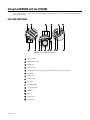
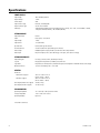
I N S T A L L A T I O N
KBD5000 Keyboard
C1620M-G (11/10)
Contents
Important Notices . . . . . . . . . . . . . . . . . . . . . . . . . . . . . . . . . . . . . . . . . . . . . . . . . . . . . . . . . . . . . . . . . . . . . . . . . . . . . . . . . . . . . . . . . . . . . . . . . . . . . 5
Regulatory Notices . . . . . . . . . . . . . . . . . . . . . . . . . . . . . . . . . . . . . . . . . . . . . . . . . . . . . . . . . . . . . . . . . . . . . . . . . . . . . . . . . . . . . . . . . . . . . . . . 5
Description. . . . . . . . . . . . . . . . . . . . . . . . . . . . . . . . . . . . . . . . . . . . . . . . . . . . . . . . . . . . . . . . . . . . . . . . . . . . . . . . . . . . . . . . . . . . . . . . . . . . . . . . . . . 6
Parts List . . . . . . . . . . . . . . . . . . . . . . . . . . . . . . . . . . . . . . . . . . . . . . . . . . . . . . . . . . . . . . . . . . . . . . . . . . . . . . . . . . . . . . . . . . . . . . . . . . . . . . . . 6
Package Contents . . . . . . . . . . . . . . . . . . . . . . . . . . . . . . . . . . . . . . . . . . . . . . . . . . . . . . . . . . . . . . . . . . . . . . . . . . . . . . . . . . . . . . . . . . . . . . . . . 7
Product Serial Number Label . . . . . . . . . . . . . . . . . . . . . . . . . . . . . . . . . . . . . . . . . . . . . . . . . . . . . . . . . . . . . . . . . . . . . . . . . . . . . . . . . . . . . . . . 7
Rear Panel Connectors. . . . . . . . . . . . . . . . . . . . . . . . . . . . . . . . . . . . . . . . . . . . . . . . . . . . . . . . . . . . . . . . . . . . . . . . . . . . . . . . . . . . . . . . . . . . . . . . . . 8
Installation . . . . . . . . . . . . . . . . . . . . . . . . . . . . . . . . . . . . . . . . . . . . . . . . . . . . . . . . . . . . . . . . . . . . . . . . . . . . . . . . . . . . . . . . . . . . . . . . . . . . . . . . . . . 9
Installing the Wrist Support . . . . . . . . . . . . . . . . . . . . . . . . . . . . . . . . . . . . . . . . . . . . . . . . . . . . . . . . . . . . . . . . . . . . . . . . . . . . . . . . . . . . . . . . . 9
Rotating the Modules . . . . . . . . . . . . . . . . . . . . . . . . . . . . . . . . . . . . . . . . . . . . . . . . . . . . . . . . . . . . . . . . . . . . . . . . . . . . . . . . . . . . . . . . . . . . . . 9
Connecting the Keyboard . . . . . . . . . . . . . . . . . . . . . . . . . . . . . . . . . . . . . . . . . . . . . . . . . . . . . . . . . . . . . . . . . . . . . . . . . . . . . . . . . . . . . . . . . . 10
Turning on the Power . . . . . . . . . . . . . . . . . . . . . . . . . . . . . . . . . . . . . . . . . . . . . . . . . . . . . . . . . . . . . . . . . . . . . . . . . . . . . . . . . . . . . . . . . . . . . 10
Using the KBD5000 with the VCD5202 . . . . . . . . . . . . . . . . . . . . . . . . . . . . . . . . . . . . . . . . . . . . . . . . . . . . . . . . . . . . . . . . . . . . . . . . . . . . . . . . . . . . 11
Keys and Functions . . . . . . . . . . . . . . . . . . . . . . . . . . . . . . . . . . . . . . . . . . . . . . . . . . . . . . . . . . . . . . . . . . . . . . . . . . . . . . . . . . . . . . . . . . . . . . . 11
Overview of VCD5202 Menus . . . . . . . . . . . . . . . . . . . . . . . . . . . . . . . . . . . . . . . . . . . . . . . . . . . . . . . . . . . . . . . . . . . . . . . . . . . . . . . . . . . . . . 12
Displaying and Hiding the System Menus . . . . . . . . . . . . . . . . . . . . . . . . . . . . . . . . . . . . . . . . . . . . . . . . . . . . . . . . . . . . . . . . . . . . . . . . 12
Selecting a Menu Item . . . . . . . . . . . . . . . . . . . . . . . . . . . . . . . . . . . . . . . . . . . . . . . . . . . . . . . . . . . . . . . . . . . . . . . . . . . . . . . . . . . . . . . 12
Displaying Online Help . . . . . . . . . . . . . . . . . . . . . . . . . . . . . . . . . . . . . . . . . . . . . . . . . . . . . . . . . . . . . . . . . . . . . . . . . . . . . . . . . . . . . . . 12
Troubleshooting . . . . . . . . . . . . . . . . . . . . . . . . . . . . . . . . . . . . . . . . . . . . . . . . . . . . . . . . . . . . . . . . . . . . . . . . . . . . . . . . . . . . . . . . . . . . . . . . . . . . . . 13
Specifications . . . . . . . . . . . . . . . . . . . . . . . . . . . . . . . . . . . . . . . . . . . . . . . . . . . . . . . . . . . . . . . . . . . . . . . . . . . . . . . . . . . . . . . . . . . . . . . . . . . . . . . 14
C1620M-G (11/10)
3
List of Illustrations
1
2
3
4
5
6
4
Package Contents . . . . . . . . . . . . . . . . . . . . . . . . . . . . . . . . . . . . . . . . . . . . . . . . . . . . . . . . . . . . . . . . . . . . . . . . . . . . . . . . . . . . . . . . . . . . . . . . . 7
Product Serial Number Label . . . . . . . . . . . . . . . . . . . . . . . . . . . . . . . . . . . . . . . . . . . . . . . . . . . . . . . . . . . . . . . . . . . . . . . . . . . . . . . . . . . . . . . . 7
Rear Panel Connectors . . . . . . . . . . . . . . . . . . . . . . . . . . . . . . . . . . . . . . . . . . . . . . . . . . . . . . . . . . . . . . . . . . . . . . . . . . . . . . . . . . . . . . . . . . . . . 8
Installing the Wrist Support . . . . . . . . . . . . . . . . . . . . . . . . . . . . . . . . . . . . . . . . . . . . . . . . . . . . . . . . . . . . . . . . . . . . . . . . . . . . . . . . . . . . . . . . 9
Connecting the KBD5000 to a VCD5202. . . . . . . . . . . . . . . . . . . . . . . . . . . . . . . . . . . . . . . . . . . . . . . . . . . . . . . . . . . . . . . . . . . . . . . . . . . . . . . 10
Keys and Keyboard Functions. . . . . . . . . . . . . . . . . . . . . . . . . . . . . . . . . . . . . . . . . . . . . . . . . . . . . . . . . . . . . . . . . . . . . . . . . . . . . . . . . . . . . . . 11
C1620M-G (11/10)
Important Notices
REGULATORY NOTICES
This device complies with Part 15 of the FCC Rules. Operation is subject to the following two conditions: (1) this device may not cause
harmful interference, and (2) this device must accept any interference received, including interference that may cause undesired operation.
RADIO AND TELEVISION INTERFERENCE
This equipment has been tested and found to comply with the limits of a Class B digital device, pursuant to Part 15 of the FCC Rules. These
limits are designed to provide reasonable protection against harmful interference in a residential installation. This equipment generates,
uses, and can radiate radio frequency energy and, if not installed and used in accordance with the instructions, may cause harmful
interference to radio communications. However there is no guarantee that the interference will not occur in a particular installation. If this
equipment does cause harmful interference to radio or television reception, which can be determined by turning the equipment off and on,
the user is encouraged to try to correct the interference by one or more of the following measures:
•
Reorient or relocate the receiving antenna.
•
Increase the separation between the equipment and the receiver.
•
Connect the equipment into an outlet on a circuit different from that to which the receiver is connected.
•
Consult the dealer or an experienced radio/TV technician for help.
You may also find helpful the following booklet, prepared by the FCC: “How to Identify and Resolve Radio-TV Interference Problems.” This
booklet is available from the U.S. Government Printing Office, Washington D.C. 20402.
Changes and Modifications not expressly approved by the manufacturer or registrant of this equipment can void your authority to operate this
equipment under Federal Communications Commission’s rules.
In order to maintain compliance with FCC regulations shielded cables must be used with this equipment. Operation with non-approved
equipment or unshielded cables is likely to result in interference to radio and television reception.
This Class B digital apparatus complies with Canadian ICES-003.
Cet appareil numérique de la classe B est conforme à la norme NMB-003 du Canada.
C1620M-G (11/10)
5
Description
The KBD5000 keyboard is the controller for Pelco’s network-based video system products. All user functions can be accessed from
the KBD5000.
The KBD5000 is configured with three control modules that are installed in receptacles on the keyboard base. The following three modules
are included with the base:
•
A variable speed, vector-solving joystick with keys for lens, iris, and focus control. The barrel-type joystick provides precise pan and tilt
control of fixed speed and variable speed positioning systems. Twisting the joystick zooms the lens in and out. The joystick and trigger are
also used for navigating the on-screen programming menus.
•
A jog dial and shuttle ring for playback and menu navigation. The jog/shuttle contains four illuminated function keys. The color of each key
corresponds to the color of its icon displayed on the monitors linked to the user interface. This intuitive color-coded design lets users
navigate the on-screen menus without looking down to read keyboard text labels.
•
A keypad for camera and monitor control. Keys can be used to select cameras and monitors and the number of cameras to view.
The KBD5000 can be logically configured so any number of keyboards can be added to the system. When combined with Pelco’s new user
interfaces (UIs), network video recorders (NVRs), and encoders, the KBD5000 forms an integral part of a complete network-based video
control system.
The KBD5000 is connected to a USB port on the VCD5202 video console display (VCD). Together, this pair provides the traditional user
keyboard functionality as well as full access to network-based operations and settings. Users can access operational functions displayed as
semitransparent graphical overlays on the monitor.
PARTS LIST
Qty
1
1
4
1
3
1
1
1
6
Description
Keyboard base with three modules
Wrist support
Screws, 4-40 x 0.312-inch, Phillips pan head
Power supply
Power cords (1 USA standard, 1 UK standard, and 1 European standard)
USB Type B-to-Type A cable with screw attachment, 16.4 ft (5.0 m) long
KBD5000 Installation/Operation manual
Safety instructions
C1620M-G (11/10)
PACKAGE CONTENTS
When installing the KBD5000, refer to Figure 1.
ACCESSORY PACK
SAFETY INSTRUCTIONS
AND MANUAL
KEYBOARD
1 EA.
POWER SUPPLY
AND USB CABLE
1 EA.
USA STANDARD
POWER CORD
(110 VAC)
1 EA.
WRIST SUPPORT
1 EA.
SHOWN ACTUAL SIZE
PHILLIPS PAN
HEAD SCREW
4-40 X .312-INCH
4 EA.
EUROPEAN
STANDARD POWER
CORD (220 VAC)
1 EA.
UK
STANDARD POWER
CORD (250 VAC)
1 EA
Figure 1. Package Contents
PRODUCT SERIAL NUMBER LABEL
A label citing your unit’s product serial number is attached to the bottom of your KBD5000 keyboard base. Should your unit require service,
the product serial number label helps Pelco Product Support personnel identify your system and its factory configuration.
Model
MODEL
03267-39-0020
SN
FREQ
50/60HZ
AMPS
Sample Text
VOLTS
Sample Text
REV
Sample Text
Audio/Video Apparatus
91KK
MFG BY PELCO, CLOVIS, CA MADE IN USA
Figure 2. Product Serial Number Label
C1620M-G (11/10)
7
Rear Panel Connectors
Figure 3. Rear Panel Connectors
Input Power
USB Type A Port
USB Type B Port (attaches to a VCD5202; use the supplied Type B-to-Type A adapter cable)
Headphone Connector/Speaker
Microphone Connector
NOTES:
8
•
Any USB cable attached to the keyboard must be no longer than 16.4 feet (5.0 m).
•
You can use the USB ports to export video, clips, or still images. To do so, the port must be connected to a USB hard drive or USB memory
key. USB CD/DVD drives are not supported.
C1620M-G (11/10)
Installation
INSTALLING THE WRIST SUPPORT
The KBD5000 comes with three control modules that fit in three receptacles on the base. The setup from the factory has the jog/shuttle
module installed on the left side of the base, the keypad module in the center, and the joystick module on the right.
The KBD5000 also has a wrist support that can be easily installed and removed (the keyboard can be used without the wrist support). This
system allows custom tailoring of the keyboard to your preferences.
Perform the following steps to install the wrist support:
1. Remove the base and wrist support from their packaging.
2. Turn the keyboard upside down (refer to Figure 4). Attach the wrist support by first lining up the four tabs on the wrist support with the four
matching screw receptacles on the base. Install the four 4-40 x 0.312-inch Phillips pan head screws (supplied).
Figure 4. Installing the Wrist Support
ROTATING THE MODULES
WARNING: Rotating the module with a pinched cable can damage the cable. To avoid tangling the cable, do not rotate the module more
than 45 degrees from center.
The KBD5000 lets you rotate each module to a comfortable position, and each module can be rotated in its receptacle. To rotate a module,
push against the raised plastic tabs on the module.
C1620M-G (11/10)
9
CONNECTING THE KEYBOARD
To connect the KBD5000, you must attach the USB Type B-to-Type A cable (supplied) from the USB connector on the rear of the KBD5000 to
the USB connector on either the front or rear of the Pelco VCD5202 video console display. (For example, Figure 5 shows a connection to
either the rear or front of a VCD5202.)
NOTE: Any USB cable attached to the keyboard must be no longer than 16.4 feet (5.0 m).
VCD5202 FRONT PANEL (BEZEL OFF)
OR
VCD5202 REAR PANEL
Figure 5. Connecting the KBD5000 to a VCD5202
TURNING ON THE POWER
To apply power:
1. Insert the power supply cord (attached) into the back of the keyboard, and tighten the connector barrel.
2. Insert the appropriate supplied power cord (USA standard, UK standard, or European standard) into the power supply.
3. Insert the power cord into a properly grounded power socket. When power is applied, lights on the modules illuminate.
10
C1620M-G (11/10)
Using the KBD5000 with the VCD5202
The following information is a simple guide for using the KBD5000. For detailed operating instructions, refer to the VCD5202 Video Console
Display Operation manual.
KEYS AND FUNCTIONS
1
2
ab
c
4
gh
i
3
de
f
5
jkl
7
pqrs
6
mno
8
tuv
0
9
wxy
z
Figure 6. Keys and Keyboard Functions
Camera Selection
Keypad (Numbers 0 to 9)
Multiple View
Monitor Selection
Color-Coded Function Keys (blue, yellow, green, and red): Keys correspond to screen menus
Record Video
Menu Selection
Play/Pause Video
Jog/Shuttle
Live Playback Mode
Joystick with Trigger
Iris/Plus (+)
Help
Aux (Auxiliary)
Focus/Minus (–)
C1620M-G (11/10)
11
OVERVIEW OF VCD5202 MENUS
The KBD5000 works in conjunction with the VCD5202 video console display and its menus. Refer to the VCD5202 Video Console Display
Operation manual for operating information.
DISPLAYING AND HIDING THE SYSTEM MENUS
To display or hide on-screen menus, press one of the menu keys on the jog/shuttle module.
SELECTING A MENU ITEM
The following tools can be used to select a menu item:
•
Joystick: Move between the on-screen menus.
•
Colored function keys: Select a menu item.
•
Jog/shuttle: Move across a menu or up and down in a list.
Using the Joystick and On-Screen Back Icon
To navigate to a menu item, use the joystick to move the yellow cursor left or right, and then press the joystick trigger to select an item.
To return to a previous menu, navigate to Back, and then press the joystick trigger.
Using the Color-Coded Keys
The KBD5000 keyboard contains four color-coded function keys. The color of each key corresponds to the color of its icon, which is displayed on
the monitors linked to the VCD5202. This color-coded design lets you navigate the on-screen menus without looking down to read keyboard text
labels. The colors always appear in the same order from left to right: blue, yellow, green, and red.
To navigate to the next level in the menu or to select an item, press the color-coded function key that corresponds to the on-screen menu icon.
To return to a previous menu, turn the shuttle (outer ring) to the left. After you make a selection, a menu or dialog box appears.
Returning to a Previous Menu
There are two ways to return to a previous or higher level menu:
•
Navigate to Back, and then press the joystick trigger.
•
Turn the shuttle (outer ring) to the left.
DISPLAYING ONLINE HELP
To open the Help dialog box:
1. Open the Main menu.
2. Select Help.
3. Press the blue function key; the KBD5000 online Help dialog box appears. There is a dialog box for each module.
12
C1620M-G (11/10)
Troubleshooting
If you need assistance, contact Pelco Product Support at 1-800-289-9100 (USA and Canada) or +1-559-292-1981 (International). Be sure to
have the serial number located on the bottom of the keyboard available in case it is needed.
Do not try to repair the keyboard yourself; opening it immediately voids any warranty. Leave maintenance and repairs to qualified technical
personnel. Remove the defective unit and return it for repair.
C1620M-G (11/10)
13
Specifications
POWER SUPPLY
Input Voltage
Output Voltage
Power Output
Input Connector Type
Output Connector Type
Cable Type
100 to 240 VAC, 50/60 Hz
12 VDC
20 W
Universal, interchangeable
2.5 mm screw-on barrel
Supplied with grounded power cord; molded connector, 3 prongs, 6 ft (1.8 m); 1 USA standard (110 VAC),
1 European standard (220 VAC), 1 UK standard (250 VAC)
KEYBOARD BASE
Keyboard Interface
USB 2.0
Cable
USB, captive, 16.4 ft (5.0 m)
Input Voltage
12 VDC
Input Current
1.3 A (maximum)
Upstream Port
USB 2.0 (USB Type B connector)
Downstream Ports
2 USB 2.0 Hi/Full/Low speed (USB Type A connector)
Audio Output
Embedded speaker or plug-in headset, 0.5 W into 8-ohm load per channel
Audio Input*
Plug-in microphone, mono (30 to 350 mVp-p), or line input, stereo (0.35 to 2.0 Vp-p)
KEYBOARD MODULES
Keyboard Keypad
0 to 9 keys, camera, monitor, and multiple view keys
Joystick
Fully proportional pan and tilt, variable speed; with zoom
Jog/Shuttle
Proportional, fast forward, reverse, and video transport; menu navigation on VCD5202 virtual console display
Module Connectors
3 (one for each module), USB 1.1 mini USB
GENERAL
Dimensions
Without Wrist Support
With Wrist Support
7.86" D x 14.78" W x 4.6" H
(19.96 x 37.54 x 11.68 cm)
9.94" D x 16.88" W x 4.6" H
(25.25 x 42.88 x 11.68 cm)
Unit Weight (without wrist support)
2.68 lb (1.22 kg)
Unit Weight (with wrist support)
3.32 lb (1.51 kg)
ENVIRONMENTAL
Operating Temperature
Storage Temperature
Operating Humidity
32° to 104°F (0° to 40°C) at unit air intake
–40° to 149°F (–40° to 65°C)
Up to 96%
*Reserved for future use.
14
C1620M-G (11/10)
PRODUCT WARRANTY AND RETURN INFORMATION
WARRANTY
Pelco will repair or replace, without charge, any merchandise proved defective in
material or workmanship for a period of one year after the date of shipment.
Exceptions to this warranty are as noted below:
• Five years:
– Fiber optic products
– Unshielded Twisted Pair (UTP) transmission products
– CC3701H-2, CC3701H-2X, CC3751H-2, CC3651H-2X, MC3651H-2, and
MC3651H-2X camera models
• Three years:
– Pelco-designed fixed network cameras and network dome cameras with
Sarix™ technology.
– Pelco-branded fixed camera models (CCC1390H Series, C10DN Series,
C10CH Series, and IP3701H Series)
– EH1500 Series enclosures
– Spectra® IV products (including Spectra IV IP)
– Camclosure® Series (IS, ICS, IP) integrated camera systems
– DX Series digital video recorders (except DX9000 Series which is covered
for a period of one year), DVR5100 Series digital video recorders, Digital
Sentry® Series hardware products, DVX Series digital video recorders, and
NVR300 Series network video recorders
– Endura® Series distributed network-based video products
– Genex® Series products (multiplexers, server, and keyboard)
– PMCL200/300/400 Series LCD monitors
– PMCL5xx Series FHD monitors
• Two years:
– Standard varifocal, fixed focal, and motorized zoom lenses
– DF5/DF8 Series fixed dome products
– Legacy® Series integrated positioning systems
– Spectra III™, Spectra Mini, Spectra Mini IP, Esprit®, ExSite®, and PS20
scanners, including when used in continuous motion applications.
– Esprit Ti and TI2500 Series thermal imaging products
– Esprit and WW5700 Series window wiper (excluding wiper blades).
– CM6700/CM6800/CM9700 Series matrix
– Digital Light Processing (DLP®) displays (except lamp and color wheel). The
lamp and color wheel will be covered for a period of 90 days. The air filter is
not covered under warranty.
– Intelli-M® eIDC controllers
• One year:
– Video cassette recorders (VCRs), except video heads. Video heads will be
covered for a period of six months.
• Six months:
– All pan and tilts, scanners, or preset lenses used in continuous motion
applications (preset scan, tour, and auto scan modes).
Pelco will warrant all replacement parts and repairs for 90 days from the date of
Pelco shipment. All goods requiring warranty repair shall be sent freight prepaid
to a Pelco designated location. Repairs made necessary by reason of misuse,
alteration, normal wear, or accident are not covered under this warranty.
Pelco assumes no risk and shall be subject to no liability for damages or loss
resulting from the specific use or application made of the Products. Pelco’s liability
for any claim, whether based on breach of contract, negligence, infringement of
any rights of any party or product liability, relating to the Products shall not exceed
the price paid by the Dealer to Pelco for such Products. In no event will Pelco be
liable for any special, incidental, or consequential damages (including loss of use,
loss of profit, and claims of third parties) however caused, whether by the
negligence of Pelco or otherwise.
The above warranty provides the Dealer with specific legal rights. The Dealer may
also have additional rights, which are subject to variation from state to state.
If a warranty repair is required, the Dealer must contact Pelco at (800) 289-9100 or
(559) 292-1981 to obtain a Repair Authorization number (RA), and provide the
following information:
1. Model and serial number
2. Date of shipment, P.O. number, sales order number, or Pelco invoice number
3. Details of the defect or problem
If there is a dispute regarding the warranty of a product that does not fall under
the warranty conditions stated above, please include a written explanation with
the product when returned.
Method of return shipment shall be the same or equal to the method by which the
item was received by Pelco.
RETURNS
To expedite parts returned for repair or credit, please call Pelco at (800) 289-9100
or (559) 292-1981 to obtain an authorization number (CA number if returned for
credit, and RA number if returned for repair) and designated return location.
All merchandise returned for credit may be subject to a 20 percent restocking and
refurbishing charge.
Goods returned for repair or credit should be clearly identified with the assigned
CA or RA number and freight should be prepaid.
2-10-10
The materials used in the manufacture of this document and its components are compliant to the requirements of Directive 2002/95/EC.
This equipment contains electrical or electronic components that must be recycled properly to comply with Directive 2002/96/EC of the European Union
regarding the disposal of waste electrical and electronic equipment (WEEE). Contact your local dealer for procedures for recycling this equipment.
REVISION HISTORY
Manual #
C1620M
C1620M-A
C1620M-B
Date
10/04
4/05
9/05
C1620M-C
C1620M-D
C1620M-E
C1620M-F
C1620M-G
5/06
10/06
9/07
11/08
11/10
Comments
Original version.
In the specifications, included dimensions and weight for a unit with the wrist support.
Revised the parts list to include a UK power cable, and moved the parts list to page 4. Added a package contents drawing, which became the new Figure 1. Added
the cable type to the specifications page. Revised Figure 6.
Revised figures 1 and 6 and changed the installation instructions because the pods are now being installed at the factory.
Revised figures 3 and 6 to reflect changes to the rear panel. In the Specifications section, revised operating and storage temperatures and added ambient temperature.
Revised parts list and package contents.
Added new information on Iris/Plus and Focus/Minus key combinations and functions.
Updated VCD5000 to VCD5202 in text and graphics. Updated warranty page.
Pelco, the Pelco logo, and other trademarks associated with Pelco products referred to in this publication are trademarks of Pelco, Inc. or its affiliates.
All other product names and services are the property of their respective companies.
Product specifications and availability are subject to change without notice.
© Copyright 2010, Pelco, Inc.
All rights reserved.
www.pelco.com
Pelco by Schneider Electric 3500 Pelco Way Clovis, California 93612-5699 United States
USA & Canada Tel (800) 289-9100 Fax (800) 289-9150
International Tel +1 (559) 292-1981 Fax +1 (559) 348-1120