1
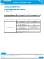
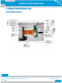
THERMAL PRINTER DRIVER CARD
THERMAL PRINTER
DRIVER CARD
User Manual – Rev.A4
Y.Yusup Khan
CASCADEMIC Solutions Pvt.Ltd.
18-June-2015
1
THERMAL PRINTER DRIVER CARD
Project Name
:
Thermal Printer Driver Card
Document Number
:
CS-P00R-UM-1K-Rev.A4
Doc. Description
:
User Manual
Part Number
:
CS-MTPR-Cxy
Department
:
Solution - Printer
Contact Details
:
CASCADEMIC Solutions Pvt. Ltd.
Email: [email protected],
Document Owner(s)
Project Role
Prepared By:
Yusup Khan
Approved By:
Prabhu . C
Signature
Proprietary Notice: This document contains proprietary material for the sole use of the intended
recipient(s). Do not read or print this document if you are not the intended recipient. Any review, use,
distribution or disclosure by others is strictly prohibited. If you are not the intended recipient, you are
hereby notified that any disclosure, copying distribution or use of any of the information contained
within this document is strictly prohibited.
All registered trademarks and product names mentioned in this publication are used for identification
purposes only. The registered trademarks are the property of their respective owners.
CASCADEMIC continuously enhances and update the Solutions. Hence it reserves the right to change
details in this publication including but not limited to any specification without notice.
Revision History
Version
Date
Author
Change Description
A4
06-May-2015
Yusup Khan
Document updated
2
THERMAL PRINTER DRIVER CARD
Table of Contents
1. PART NUMBER DESCRIPTION:........................................................................................................4
1.1 MODULE (PRINTER DRIVER CARD) – CS-MTPR-Cxy..........................................................4
2. DRIVER CARD FEATURES:...............................................................................................................5
3. THERMAL PRINTER DRIVER CARD:..............................................................................................6
3.1 CS-MTPR-AA1 ( Type 1B )............................................................................................................6
3.2 CS-MTPR-Bxy ( Type 2)................................................................................................................7
3.4 POWER SUPPLY:...........................................................................................................................8
3.5 LED INDICATION:........................................................................................................................8
3.5.1 TYPE 1B - PRINTER DRIVER CARD.................................................................................8
3.5.2 TYPE 2 - PRINTER DRIVER CARD...................................................................................8
3.6 PRINTER HEAD MECHANISM...................................................................................................9
3.6.1 CS-STPR-CAy ( 2 INCH SEIKO HEAD)..............................................................................9
3.6.2 CS-STPR-BBy ( 3 INCH SEIKO HEAD).............................................................................9
3.6.3 CS-STPR-BEy ( 2 INCH SEIKO HEAD WITH AUTO-CUTTER)....................................10
3.6.4 CS-STPR-BFy ( 3 INCH SEIKO HEAD WITH AUTO CUTTER)....................................10
3.7 INTERFACE SPECIFICATION:..................................................................................................11
3.7.1. CS-STPR-AA1 (Serial Interface):........................................................................................11
3.7.2. CS-STPR-AA4 (Bluetooth Interface):..................................................................................11
3.7.3. CS-STPR-AA5 (Wi-Fi Interface):........................................................................................11
3.8 PROCESS OF LOADING THE THERMAL PAPER...................................................................11
4. COMMAND SPECIFICATIONS........................................................................................................12
4.1. SELECT FONT TYPE:................................................................................................................12
4.2. SELECT LINE ALIGNMENT:....................................................................................................13
4.3. LINE SPACING:..........................................................................................................................14
4.4. PRINT AND LINE FEED:...........................................................................................................14
4.5. TEST PRINT:...............................................................................................................................14
4.6. TO CHANGE BAUD RATE:.......................................................................................................15
4.7. PRINT FEED N LINES:..............................................................................................................15
4.8. PRINT REVERSE FEED N LINES:...........................................................................................15
4.9. PRINT BAR CODE:....................................................................................................................16
4.10. HINDI PRINT:...........................................................................................................................18
4.11. TO PRINT LOGO:.....................................................................................................................20
4.12. TO PRINT TEST PAGE:............................................................................................................41
4.13. TO PAPER FEED:......................................................................................................................41
5. HANDLING PRECAUTIONS............................................................................................................42
6. HANDLING METHOD......................................................................................................................44
6.1 INSTALLING/UNINSTALLING THE THERMAL PAPER.......................................................44
6.1.1. PROCEDURES FOR INSTALLING/UNINSTALLING THERMAL PAPER...................44
6.1.2. PRECAUTIONS FOR INSTALLING/UNINSTALLING THERMAL PAPER..................44
3
THERMAL PRINTER DRIVER CARD
1. PART NUMBER DESCRIPTION:
1.1 MODULE (PRINTER DRIVER CARD) – CS-MTPR-Cxy
Cxy– Configuration number
C: (Module Configuration)
x: (Major Feature Configuration)
y: (Minor Feature Configuration)
A – Driver card type 1B
A – 2 Inch
1 – Serial(TTL)
Driver card type 1B (70mm x 20mm): Without Battery Support
C: (Module Configuration)
B – Driver card type 2
x: (Major Feature Configuration)
y: (Minor Feature Configuration)
A – 2 Inch
1 – Serial(TTL)
B – 3 Inch
2 – USB
C – 2 Inch + Mechanism
3 – BLE
D – 3 Inch+ Mechanism
4 – BT
E – 2 Inch + Cutter
5 – WiFi (802.11b/g/n)
F – 3 Inch + Cutter
G – 2 Inch + Cutter+Mechanism
H – 3 Inch + Cutter+Mechanism
Driver card type 2 (70mm x 35mm): With Battery Support
4
THERMAL PRINTER DRIVER CARD
2. DRIVER CARD FEATURES:
The thermal printer interface card has the following features
1. Interface: UART(TTL level-3.3V)/BT/BLE/WiFi.
2. Baud rate can be configured. (Default is 9600)
3. Barcode printing.
4. Font support. (English – Verdana, Courier)
5. Regional language (Marathi, Hindi).
6. Text print support.
7. Image/Logo print.
8. LED indication for Paper and platen detect options.
9. Power: 7.5V-9V, 3A. Powered via Adapter/Battery.
10. Supported SEIKO Printers:
i.
LTP01-245
-
2Inch
ii. CAPD245
-
2Inch with Cutter
iii. LTPD345
-
3Inch
iv. CAPD345
-
3Inch with Cutter
Kit Deliverables
1. Thermal Printer Interface Card.
2. LTP01-245/CAPD245/LTPD345/CAPD345(SEIKO)(optional)
3. 2 inch/3 inch Paper Roll – 1 No
5
THERMAL PRINTER DRIVER CARD
3. THERMAL PRINTER DRIVER CARD:
3.1 CS-MTPR-AA1 ( Type 1B )
6
THERMAL PRINTER DRIVER CARD
3.2 CS-MTPR-Bxy ( Type 2)
Top View:
7
THERMAL PRINTER DRIVER CARD
Bottom View:
3.4 POWER SUPPLY:
The Power supply to be used has to be (7.5V-9V / 3A) through external adapter. Also separate slot is provided
for battery power (7.5V-9V / 3A). Power adapter is positive polarity.
3.5 LED INDICATION:
3.5.1 TYPE 1B - PRINTER DRIVER CARD
Board consists of 3 LEDs as follows:
1. POWER ON INDICATION LED: This LED will turn ON, when 7.5V / 3A power is applied to the Thermal
Printer Card.
2. STATUS LED : This LED will turn ON while Printing.
3. PLATEN DETECTION LED : This LED will turn ON when Platen is not connected to the printer.
3.5.2 TYPE 2 - PRINTER DRIVER CARD
Board consists of 2 LEDs as follows:
1. POWER / ERROR INDICATION LED: This LED will turn ON , when 7.5V / 3A power is applied to the
Thermal Printer Card and will blink in case of an error.
2. STATUS LED : This LED will turn ON while Printing.
8
THERMAL PRINTER DRIVER CARD
3.6 PRINTER HEAD MECHANISM
3.6.1 CS-STPR-CAy ( 2 INCH SEIKO HEAD)
LTP01-245-12
Model
Auto Cutter
No
Characters per line
24/32/48
Maximum print speed (mm/s)
75
Print Width
48
Paper width
58
Out of Paper Indication
Yes
Platen Position Indication
Yes
Power Supply
Maximum (V)
4.75
Minimum (V)
9.5
3.6.2 CS-STPR-BBy ( 3 INCH SEIKO HEAD)
LTPD345
Model
Auto Cutter
No
Characters per line
36/48/72
Maximum print speed (mm/s)
80
Print Width
72
Paper width
80
Out of Paper Indication
Yes
Platen Position Indication
Yes
Power Supply
Maximum (V)
4.75
Minimum (V)
9.5
9
THERMAL PRINTER DRIVER CARD
3.6.3 CS-STPR-BEy ( 2 INCH SEIKO HEAD WITH AUTO-CUTTER)
CAPD245
Model
Yes
Auto Cutter
Characters per line
24/32/48
Maximum print speed (mm/s)
100
Print Width
48
Paper width
58
Out of Paper Indication
Yes
Platen Position Indication
Yes
Power Supply
Maximum (V)
4.75
Minimum (V)
9.5
3.6.4 CS-STPR-BFy ( 3 INCH SEIKO HEAD WITH AUTO CUTTER)
CAPD345
Model
Auto Cutter
Yes
Characters per line
36/48/72
Maximum print speed (mm/s)
80
Print Width
72
Paper width
80
Out of Paper Indication
Yes
Platen Position Indication
Yes
Power Supply
Maximum (V)
6.5
Minimum (V)
9.5
10
THERMAL PRINTER DRIVER CARD
3.7 INTERFACE SPECIFICATION:
3.7.1. CS-STPR-Cx1 (Serial Interface):
COM Port Settings:
1.
2.
3.
4.
5.
Bits per Second
Data Bits
Parity
Stop Bits
Flow Control
:
:
:
:
:
9600
8
None
1
None
3.7.2. CS-STPR-Bx4 (Bluetooth Interface):
1. Name of the Blue-tooth device is “CAS BT PRINTER” and Password is “1234”.
2. Searching won’t stop until the device is found. Configure the connection between the
master and slave(CAS BT PRINTER). Master can send data to slave and request from slave as
well.
3. You are allowed to transmit and receive data through Blue Term+
Bluetooth Specification:
1. Blue-tooth protocol :
Blue-tooth Specification v2.0 + EDR
2. Frequency
:
2.4GHz ISM band
3. Profiles
:
Blue-tooth serial port
4. Power supply
:
Built-in Chip antenna power supply + 3.3VDC 50mA
5. Dimension
:
26.9mm x 13mm x 2.2 mm
3.7.3. CS-STPR-Bx5 (Wi-Fi Interface):
1. Name of the Wi-Fi device is “CAS Wi-Fi PRINTER” and Password is “12345678”.
2. Searching won’t stop until the device is found. Configure the connection between the
master and slave device (CAS Wi-Fi PRINTER). Master can send data to slave and request
from slave as well.
3. You are allowed to transmit and receive data through TCP Client.
4. IP Settings
:
192.168.16.254
5. Port Settings
:
8080
3.8 PROCESS OF LOADING THE THERMAL PAPER
1. Remove the platen slowly.
2. Replace the paper and Load the platen back to its position.
3. Make sure that the platen is placed properly. If not placed properly it is indicated by LED .
11
THERMAL PRINTER DRIVER CARD
4. COMMAND SPECIFICATIONS
4.1. SELECT FONT TYPE:
[Command]
:
$1Bwxyz<Space>
[Range]
:
0≤w≤1
x = 'N' or 'B'
0≤y≤2
0≤z≤7
Font (w)
Style (x)
Characters per line (y)
Size (z)
0
Courier font
1
Calibri font
N
Normal
B
Bold
0
24
1
32
2
48
0
Width=1,Height=1
1
Width=1,Height=2
2
Width=1,Height=3
3
Width=1,Height=4
4
Width=2,Height=1
5
Width=2,Height=2
6
Width=2,Height=3
7
Width=2,Height=4
Example:
If we want bold courier font at 32 chars per line and the height at 3 and width at 1, the command is $1B0B12
12
THERMAL PRINTER DRIVER CARD
4.2. SELECT LINE ALIGNMENT:
[Command]
:
$1B61mn
[Range]
:
m=30 for Left alignment
m=31 for Center alignment
m=32 for Right alignment
[Range]
:
n < Characters per line. (Range between from 0 to Characters per line)
[Description]
:
Selects the type of alignment using m.
Characters to align = n. n should be less than characters per line.
$1B6130n
-
Left alignment
$1B6131n
-
Center alignment
$1B6132n
-
Right alignment
:
In alignment, if you want to change font, you can send font command followed
by alignment command.
[Notes]
Sample Text
$1B613012<Space>ABCDEFGHIJKLMNOPQRSTUVWXYZ
Here m = 30 and n = 12
Sample Text
$1B613108<Space>ABCDEFGHIJKLMNOPQRSTUVWXYZ
Here m = 31 and n = 08
Sample Text
$1B613205<Space>ABCDEFGHIJKLMNOPQRSTUVWXYZ
Here m = 32 and n = 05
13
THERMAL PRINTER DRIVER CARD
4.3. LINE SPACING:
Line Space On:
[Command]
:
$1B32
[Command]
:
$1B30
[Range]
:
None
[Description]
:
$1B32 Prints the data with line space. This command setting is effective until
Line Space Off:
feeding $1B30, reset or Power-off.
Sample Text
$1B32<Space>ABCDEFGHIJKLMNOPQRSTUVWXYZABCDEFGHIJKLMNOPQRSTUVWXYZABCDEFGHIJKLMNOPQR
STUVWXYZABCDEFGHIJKLMNOPQRSTUVWXYZ
Sample Text
$1B30<Space>ABCDEFGHIJKLMNOPQRSTUVWXYZABCDEFGHIJKLMNOPQRSTUVWXYZABCDEFGHIJKLMNOPQR
STUVWXYZABCDEFGHIJKLMNOPQRSTUVWXYZ
4.4. PRINT AND LINE FEED:
[Command
:
$0A
[Range]
:
None
[Description]
:
Prints the data and feed one line (‘\n’), based on current line spacing.
Sample Text
ABCDEFGH$0A<Space>IJKLMNOPQRS$0A<Space>TUVWXYZ
4.5. TEST PRINT:
[Command]
:
$1D41
[Description]
:
Executes the test print.
14
THERMAL PRINTER DRIVER CARD
4.6. TO CHANGE BAUD RATE:
[Command]
:
$1D44
[Range]
:
2400 to 230400. Default baud rate is 9600
[Description]
:
Sets the baud rate for data communication.
[Notes]
:
Once new baud rate is set, similar configuration has to be made in
Hyper Terminal.
E.g. To configure baud rate 57600 (use command $1D44 57600)
4.7. PRINT FEED N LINES:
[Command]
:
$14$0$n
[Range]
:
00 ≤ n ≤ 99 (n in millimeter)
[Description]
:
Prints data and feed “n” millimeter line spacing.
[Notes]
:
This command is used to feed a specific line without changing the line spacing
set by other commands.
4.8. PRINT REVERSE FEED N LINES:
[Command]
:
$14$1$n
[Range]
:
00 ≤ n ≤ 99 (n in millimeter)
[Description]
:
Prints data and feed “n” millimeter line spacing in reverse direction.
[Notes]
:
This command is used to feed a specific line without changing the line spacing
set by other commands.
Sample Text
ABCDEFGHIJKLMNOPQRSTUVWX$14$0$08<Space>YZABCDEFGHIJKLMNOPQRSTUV$14$1$50<Space>WXYZAB
CDEFGHIJKLMNOPQRST
Here 08 = 8mm and 50 = 50mm line spacing
15
THERMAL PRINTER DRIVER CARD
4.9. PRINT BAR CODE:
[Command]
:
$1D68m<Space>d1…..d12
[Range]
:
01 ≤ m ≤ 03
[Description]
:
Prints the bar code using the bar code height in m.
‘d’ specifies the character code data of the bar code to be printed.
The length of data ‘d’ should be 12 digits only.
[Notes]
:
Bar Code will be printed in EAN-13 format. Other formats will be implemented
based on customer request.
Sample Text
$1D6801<Space>890244221790
Here m= 01
Sample Text
$1D6802<Space>890244221790
Here m= 02
16
THERMAL PRINTER DRIVER CARD
Sample Text
$1D6803<Space>890244221790
Here m= 03
17
THERMAL PRINTER DRIVER CARD
4.10. HINDI PRINT:
[Command]
:
$1551mn<Space>
[Range]
:
01 ≤ n ≤ 04 (n for Height of font)
m=0 for Normal font
m=1 for Bold font
[Description]
:
Print normal Hindi font using $15510n and print bold Hindi font using $15511n
Hindi Font Table
.
Commands that need to be sent shall be based on the Hindi font table given above. For e.g:
18
THERMAL PRINTER DRIVER CARD
6B is a value as required to print as given in the above image
To print above character give command $1551mn<Space>6B
This letter (क ) requires combination of two values and this letter (क ) requires combination of three values.
Each Unicode separated by a comma (,). For e.g:
$1551mn<Space>F4,7D,13B,
You can send various combinations based on Hindi text that you want to print.
Note: Make sure you have sent the Hindi Font selection command before sending the data and also you can
print English with Hindi using this command ($1550<Space>English). Bar code and line alignment commands
are not supported in Hindi print. Updated Hindi Font table attached as a separate document. Refer the
document for Hindi Print.
19
THERMAL PRINTER DRIVER CARD
4.11. TO PRINT LOGO:
PROCEDURE TO CONVERT A PICTURE TO PRINT ON 2” THERMAL PRINTER:
Step 1) Select the image that you would need to print
20
THERMAL PRINTER DRIVER CARD
Step 2) Right click and open with paint
Step 3) Select and crop the exact image that you would need to print without extra white space
21
THERMAL PRINTER DRIVER CARD
Step 4) Image after cropping
Step 5)
i.
Click Resize option
ii. Under Resize, Select Pixels
22
THERMAL PRINTER DRIVER CARD
Step 6)
i.
Under Resize and Skew, Uncheck Maintain aspect ratio
ii. Reduce the Image size by using stretch/skew option
iii. Image width (Horizontal) should be equal to 192 pixels
iv. Image Height (Vertical) should be less than or equal to 48 pixels
Step 7)
i.
Click OK
ii. In our example the Width is 192 (equal to 192) and Height is 48( less than or equal to 48) as shown
above.
23
THERMAL PRINTER DRIVER CARD
Step 8) Select Save as type “Monochrome Bitmap” and Save the image.
Step 9) Click on OK option, it will ask confirmation for the changes and select yes option, your Image will change
to Black and white as shown below.
24
THERMAL PRINTER DRIVER CARD
Step 10) Black and white Image.
Step 11)
i.
Again select Save as type “JPEG”
ii. Change the File Name and Save the image.
25
THERMAL PRINTER DRIVER CARD
Step 12) From Left Side,
i.
Image (1) is bmp image
ii. Image (2) is Original image in JPEG format
iii. Image (3) is Black and White image in JPEG format.
Step 13) Go to the following link
http://www.digole.com/tools/PicturetoC_Hex_converter.php
26
THERMAL PRINTER DRIVER CARD
Step 14)
i.
Upload image(3)
ii. Enter the value of width of Image(192) in the box of Width
iii. Submit
27
THERMAL PRINTER DRIVER CARD
Step 15) Image data in bytes(Hexadecimal Values)
28
THERMAL PRINTER DRIVER CARD
Step 16)
i.
Copy the image data and paste in word document
ii. Remove 0x from all bytes
29
THERMAL PRINTER DRIVER CARD
Step 17) Convert from 00 to 0 in all bytes
30
THERMAL PRINTER DRIVER CARD
Step 18) Count the number of characters in the remaining text. In the example, the total number of characters
is 2768. The total number of words is 48.
31
THERMAL PRINTER DRIVER CARD
Step 19) Merge all the characters without any space to reduce the number of words to 1. Make sure that the
number of characters is not reduced than before.
In the example now, the total number of characters is 2768. The total number of words is 1.
Final Image data should be less than or equal to 3K characters
32
THERMAL PRINTER DRIVER CARD
Step 20) Now convert the lower case characters to upper case. This can be done by pressing “Shift+Caps
Lock+F3” twice.
33
THERMAL PRINTER DRIVER CARD
Step 21) The printing of this image can be achieved by sending Image print command followed by image data as
shown in the below image.
i.
Image print command is $1B5E$n<Space>
ii. n is Alignment of Image print
if n = 0, Left Align
if n = 1, Centre Align
if n = 2, Right Align
34
THERMAL PRINTER DRIVER CARD
4.12. TO PRINT TEST PAGE:
Press Switch SW3 to print test page.
4.13. TO PAPER FEED:
Press Switch SW5 to feed the paper for 5cm.
Note:
1. All commands should start from the beginning of the line.
2. But line feed command ($0A) can be used anywhere in the text.
3. Every command should be followed by a single space then text.
35
THERMAL PRINTER DRIVER CARD
5. HANDLING PRECAUTIONS
The following are examples of issues arising in the printer:
(1) Poor printing quality due to low thermal sensitivity
(2) Abrasion of the thermal head due to the thermal paper surface roughness
(3) Printing stuck and unusual noise due to sticking the thermal layer of the thermal paper to the thermal head
(4) Printing fades due to low preservability of the thermal paper
(5) Electrolytic corrosion of the thermal head due to inferior paper
The precautions to be taken are:
1. Do not leave the printer on for a long period of time, the platen could be deformed and resulted in
2.
3.
4.
5.
6.
print quality deteriorated. In this case, feed the thermal paper for a while to recover deformation of the
platen. If the thermal head is remained in contact with the platen without thermal paper for a long
time, the platen and the thermal head may be stuck together and cause paper feed difficulty. If facing
this problem, release the platen unit, and set it back again before starting printing.
Never loosen the screws that fasten respective parts of the printer. Loosened screws may reduce the
efficiency of the performance of the printer mechanism.
Do not release the platen unit during printing; otherwise this may reduce the efficiency of the printer
and may cause damage.
Do not apply stress to the platen unit during printing. The print defect may occur.
When setting the platen unit, the reduction gear may interfere with the platen gear and may cause the
platen unit to not be set. In such a case, release the platen unit and set it again.
Never pull out the thermal paper while the platen unit is set. The printer mechanism may become
damaged.
7. When handling the printer, make sure to use antistatic clothing and to ground yourself to prevent the
electronic parts such as thermal head, out-of-paper sensor, motor, and platen detection switch from
damaged by static electricity. Especially take care of the thermal head heat element and the connecting
terminal.
8. Do not hit or scratch the surface of the thermal head with any sharp or hard object. This could damage
the thermal head.
9. When printing at a high print ratio in a low temperature or high humidity environment, the vapor from
the thermal paper during printing may cause condensation to form on the printer and soil the thermal
paper itself. Prevent the thermal head from a drop of water. It may cause electrolytic corrosion of the
thermal head. If condensed, do not activate electricity until dried.
10. Connect or disconnect the connecting terminal after turn off the power.
11. Do not apply stress to the FPC while connecting and disconnecting them. Otherwise the FPC may
become damaged.
36
THERMAL PRINTER DRIVER CARD
12. Warn users not to pull the thermal paper and not to change the paper eject angle during printing.
Otherwise, the paper jam or the cut failure may occur.
13. In order to prevent the electronic parts such as thermal head, out-of-paper sensor, motor, and platen
detection switch from damage and to avoid the print defect, warn users not to touch the thermal head
and the sensor directly when handling the printer like replacing the thermal paper.
14. Do not use the paper roll with glued end or folded end. In case of using such paper roll, replace to a
new one before the end of the paper roll is shown up.
15. The printer is not waterproof and drip proof. Prevent contact with water and do not operate with wet
hands as it may damage the printer or may cause a short circuit or fire.
16. The printer is not dust proof. Never use the printer in a dusty place, as it may damage the thermal head
and paper drive system.
37
THERMAL PRINTER DRIVER CARD
6. HANDLING METHOD
6.1 INSTALLING/UNINSTALLING THE THERMAL PAPER
6.1.1. PROCEDURES FOR INSTALLING/UNINSTALLING THERMAL PAPER
Procedures for installing the thermal paper by the easy operation (setting and releasing the
platen block)
1. Installing the thermal paper
• Install the thermal paper with the platen unit released.
• Set the thermal paper straight to the printer and set the thermal paper until its
edge is ejected for 5 cm and more from the top surface of the printer mechanism.
2. Uninstall the thermal paper
• Uninstall the thermal paper in the same manner for installing the thermal paper.
3. Clearing a paper jam
• Uninstall the thermal paper in the same manner for installing the thermal paper.
6.1.2. PRECAUTIONS FOR INSTALLING/UNINSTALLING THERMAL PAPER
1. Install the thermal paper with the platen unit released. Auto-loading is not allowed.
2. Set the thermal paper straight to the printer and set the thermal paper until its edge is ejected
for 5 cm and more from the top surface of the printer mechanism.
3. When setting the platen unit, the reduction gear may interfere with the platen gear and may
cause the platen unit to not be set. In such a case, release the platen unit and set it again.
4. If the thermal paper is skewed, feed the thermal paper until the thermal paper becomes
straight or install the thermal paper again.
5. Remove the jamming paper with the platen unit released. Do not pull the thermal paper by
force because severe damages may occur.
6. If the thermal head is remained in contact with the platen without the thermal paper for a long
time, the platen and the thermal head may be stuck together and cause the auto-loading
difficulty. If facing this problem, release the platen block and set it back again before starting
printing.
38