1
Digital Solutions
LCDSP_TG V1.60 user manual
Serial:UART/I2C/SPI Text LCD Display Control Module
LCDSP_TG V1.60 user manual
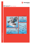
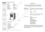
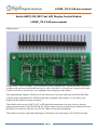
Product picture:
In order to use a Text LCD display, you need connect at least 4 data pins and 2 control pins from your circuit
to display, and you also need to spend some time to write code to drive it, in some case, you may need couple
of days to deal with it, and will give you a nightmale when changing to other display.
This control module (adapter) will help you to solve this issue, it can work with most 1602/1604/2002/2004
LCD that config with KS0066U/F / HD44780 and other compatible chips seemless, so you can use your
dispaly with this module in couple of minutes!
Tthe module can be set up as UART or I2C or SPI mode that communicate with your circuit by short the
jumper on board, and the UART BAUD and I2C address can be set up by yourself also (the module don't store
the BAUD, so it alway be 9600 after reset, but I2C address will be stored in module).
This module can connect with16pins and 20pins LCD interface, by set the jumper of SJ1 and SJ2 on board.
Page 1
Digital Solutions
LCDSP_TG V1.60 user manual
FEATURES:
Supply voltage: 1.8V to 5.5V
Communication mode: UART/I2C/SPI,
detect your setting automatically
Receiving buffer: 64 bytes
Work with KS0066U/F / HD44780 and other
compatible chips
Work with most 1602/1604/2002/2004 LCD
module
Low power consumption: 4mA maximum
Simple command sets, easy to remember
Default setting: UART baud 9600bps, I2C 0x27
address
UART baud (bps): 300, 1200, 2400, 4800, 9600,
14400, 19200, 28800, 38400, 57600, 115200
Manual, Arduino lib, sample code download here
When you need display text on LCD by using the module, just send the following command to module through
UART, I2C or SPI ("x" means a byte, "..." means varible bytes):
IMPORTANT: due to 0 is the end char of a string, and the display position start at x=0, y=0, so, if you need set
a postion of 0, you can't put the 0 in a string, you need send this byte individually.
Page 2
Digital Solutions
LCDSP_TG V1.60 user manual
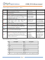
Character Display Command: (B-one byte, B…-Bytes)
Command
CL
CSB
DCB
SBB…
SI2CAB
STCRBB
BBBB
TPBB
TTB…
Description
CLear screen and set the display position to first
Column and first Row (x=0.y=0)
Arduino lib function
note
clearScreen();
enableCursor();
disableCursor();
set CurSor on/off
Display Config on/off, the factory default set is on, so,
when the module is powered up, it will display current
communication mode on LCD, after you design
finished, you can turn it off
Set UART Baud, B are ASCII characters, the
available values are: “300”, “1200”, “2400”,”4800”,
“9600”, “14400”, “19200”, “28800”, “38400”,
“57600”,”115200”
Set I2C Address,the default address is 0x27, the
adapter will store the new address in memory
Set Text Columns and Rows, this command will
config your LCD if other than 1602 and the chip is
other than KS0066U/F / HD44780
displayConfig(0);
displayConfig(1);
Set BAUT when
initial the class
When adapter power
up or reset, always
start with 9600 Baud
Change address to
0x34
The last 4 B should
setLCDColRow(20,4); be“\x80\xC0\x94\xD
4”
This will affect the
set Text Position for following display
setPrintPos(6,1);
following “TT”
command
print(string);
The print function in
display TexT string, the text will wraped in next row
print(int);
Arduino, also can
if the current row fulled, the Text Postion will be
print(char);
print other data and
changed to the last char displyed, this command ended print(float);
format the out put,
by 0x00 or 0x0D received
print(double);
please refer to
drawStr(x,y,string);
Serial.print.
setI2CAddress(0x34);
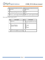
Pinout of module connect to LCD display:
PIN
1
3
5
7
9
11
13
Description
VSS Ground of circuit
V0
R/W
DB0 or D0
DB2 or D2
DB4 or D4
DB6 or D6
16pin mode:
15
BLA or A, + power supply for backlit
PIN
2
4
6
8
10
12
14
Description
VDD Power Supply
RS
E
DB1 or D1
DB3 or D3
DB5 or D5
DB7 or D7
16pin mode:
16
BLK or K, - power supply for backlit
Page 3
Digital Solutions
PIN
Description
LCDSP_TG V1.60 user manual
PIN
Description
20pin mode:
20pin mode:
N/A
N/A
20pin mode only:
20pin mode only:
17
18
RST:System reset input (low active).
VOUT
20pin mode only:
20pin mode only:
19
20
BLA or A, + power supply for backlit
BLK or K, - power supply for backlit
Pinout of this module connect to MCU:
PIN
Description
PIN
1
GND (0V)
2
3
I2C and SPI mode:
SCK/SCL: Clock in
4
5
VCC: power supply
1.8V to 5.5V depends on you LCD
Page 4
Description
SS: SPI mode only
chip select control in, low active
UART mode:
RX
I2C mode:
SDA
SPI mode:
SDI
Digital Solutions
LCDSP_TG V1.60 user manual
Config your module:
Page 5
Digital Solutions
LCDSP_TG V1.60 user manual
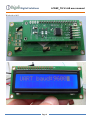
Work with a 1602:
Page 6
Digital Solutions
LCDSP_TG V1.60 user manual
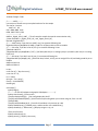
Arduino Sample Code:
/*----------NOTE---------new version of lib will save you compiled code size for the sample
The size for 2 version:
UART I2C SPI
OLD 8998 8988 9132
NEW 6966 7566 6354
------------------------*/
#define _Digole_Serial_UART_ //To tell compiler compile the special communication only,
//other available is: _Digole_Serial_I2C_ and _Digole_Serial_SPI_
#include <DigoleSerial.h>
//--------UART setup, if you don't use UART, use // to comment following line
DigoleSerialDisp mydisp(&Serial, 9600); //UART:Pin 1(TX)on arduino to RX on module
//--------I2C setup, if you don't use I2C, use // to comment following 2 lines
//#include <Wire.h>
//DigoleSerialDisp mydisp(&Wire,'\x27'); //I2C:SDA (data line) is on analog input pin 4, and SCL (clock line) is on analog
input pin 5
//--------SPI setup, if you don't use SPI, use // to comment following line
//DigoleSerialDisp mydisp(8,9,10); //SPI:Pin 8: data, 9:clock, 10: SS, you can assign 255 to SS, and hard ground SS pin on
module
#define LCDCol 16
#define LCDRow 2
int ptr;
const char a[] = "disp char array";
const char b = 'Q';
int c = 3456;
String d = "I'm a string";
float pi = 3.1415926535;
double lg10;
void setup() {
mydisp.begin();
/*----------for text LCD adapter and graphic LCD adapter ------------*/
mydisp.clearScreen(); //CLear screen
//mydisp.displayConfig(1); //set config display ON, 0=off
//mydisp.setI2CAddress(0x29); //this function only working when you connect using I2C, from 1 to 127
//delay(1000);
//mydisp.setLCDColRow(16,2); //set LCD Col and Row, only time set up is OK
mydisp.disableCursor(); //disable cursor, enable cursore use: enableCursor();
mydisp.drawStr(4, 0, "Demo now"); //display string at: x=4, y=0
//Test print function
mydisp.setPrintPos(0, 1);
mydisp.print(a); // display a char array
Page 7
Digital Solutions
LCDSP_TG V1.60 user manual
resetpos();
mydisp.print("display a char:");
mydisp.print(b); //display a char
resetpos();
mydisp.print("int as DEC:");
mydisp.print(c); //display 3456 in Dec
resetpos();
mydisp.print("as HEX:");
mydisp.print(c, HEX); //display 3456 in Hex
resetpos();
mydisp.print("as OCT:");
mydisp.print(c, OCT); //display 3456 in Oct
resetpos();
mydisp.print("BIN:");
mydisp.print(c, BIN); //display 3456 in Bin
resetpos();
mydisp.print(d); //display String object
resetpos();
mydisp.print("float pi=");
mydisp.print(pi); //display float of PI
resetpos();
mydisp.print("Pi6=");
mydisp.print(pi, 6); //display PI in 6 Accuracy
resetpos();
mydisp.print("Pi*3=");
mydisp.print(pi * 3, 6); //display PI time 3 in 6 Accuracy
resetpos();
mydisp.print("lg5=");
mydisp.print(log(5), 8); //display log(5) in 8 Accuracy
resetpos();
for (uint8_t j = 0; j < 4; j++) //making "Hello" string moving
{
for (uint8_t i = 0; i < 10; i++) //move string to right
{
mydisp.setPrintPos(i, 1);
mydisp.print(" Hello ");
delay(100); //delay 100ms
}
for (uint8_t i = 0; i < 10; i++) //move string to left
{
mydisp.setPrintPos(9 - i, 1);
mydisp.print(" Hello ");
delay(100);
}
}
mydisp.print("Enjoy it!");
Page 8
Digital Solutions
LCDSP_TG V1.60 user manual
mydisp.enableCursor(); //enable cursor
}
void resetpos(void) //for demo use, reset display position and clean the demo line
{
mydisp.setPrintPos(0, 1);
delay(2000); //delay 2 seconds
mydisp.println("
"); //display space, use to clear the demo line
mydisp.setPrintPos(0, 1);
}
void loop() {
}
Page 9