1
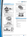
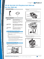
ZS-30 Spindle Unit Replacement Manual
(for the JWX-30)
Included Items
Loosen the cap screws securing the motor stay
in place.
Loosen the cap screws at the three locations.
Hexagonal wrench
Motor stay
Cap screws
3 locations
Belt
Spindle unit
How to Replace
WARNING
Disconnect the power cord before
performing replacement.
Attempting such operations while
the machine is connected to a
power source may result in injury
or electrical shock.
CAUTION
Remove the belt.
gure toward the
left side of the unit to loosen the belt, and remove the belt.
When performing replacement, be
sure to keep the tool detached.
Press here.
Contact with the blade may cause
injury.
CAUTION
Never touch the spindle unit immediately after machining.
Doing so may cause burns.
1. Getting Ready for Replacement
Belt
Carry out the following preparations.
Motor pulley
Have on hand the hexagonal wrench that came with
the main unit.
Remove the tool and collet.
Remove the spindle unit.
Move the spindle head to the VIEW position.
When you’ve finished making the preparations just described, turn off the machine’s power switch and unplug
its power cord from the electrical outlet.
For more information about how to remove the tool and the
like and how to move the spindle head, refer to the user’s
manual included with the main unit.
Loosen the two cap screws securing the spindle unit in place,
then pull out the spindle unit.
Spindle unit
2. Removing the Spindle Unit
Remove the spindle-unit cover.
Remove the cap screws at the two locations and detach the
spindle-unit cover.
Hexagonal wrench
Cap screws
2 locations
Hexagonal wrench
Cap screws
2 locations
Spindle-unit cover
RolandCare Support Documents
T | 0845 230 90 60
E | [email protected]
P age |1
W | www.rolanddg.co.uk/support
3. Installing the Spindle Unit
Secure the motor stay in place.
Tighten the cap screws at the three locations.The appropriate
tightening torque is 0.8 N-m (8 kgf-cm).
Mount the spindle unit.
Insert the spindle unit, then secure it in place using the cap
screws at the two locations. The appropriate tightening torque
is 0.8 N-m (8 kgf-cm).
Hexagonal wrench
Spindle unit
Cap screws
3 locations
Motor stay
Ensure no gap.
Attach the spindle-unit cover.
Cap screws
2 locations
Tighten the cap screws at the two locations to attach the
spindle-unit cover.
Hexagonal Wrench
Engage the belt first on the spindle unit, and
then on the motor pulley.
Orient the belt so that the white line is on the outer side.
Engage the belt on the spindle unit.
gure toward
the left side of the unit to loosen the belt, and engage the
belt on the motor pulley.
Hexagonal wrench
Cap screws
2 locations
Spindle-unit cover
4. Spindle Run-in
Press here.
Perform running-in operation for the spindle
unit.
Immediately after replacing the spindle unit, carry out steps
1 through 3 below to run in the spindle. Failure to do so may
result in unstable spindle rotation. For information on how to
rotate the spindle, refer to the user’s manual for the cutting
machine.
White line on outer side
Belt
Step1
Spindle unit
Speed: 6,000 rpm
Rotation time: 20 minutes
Motor pulley
Adjust the position of the belt.
Step2
Turning the motor pulley makes the belt move. Turn the motor pulley either clockwise or counterclockwise until the belt
gure below.
Position of the belt
Speed: 15,000 rpm
Rotation time: 20 minutes
Step3
Speed: 30,000 rpm
Rotation time: 20 minutes
Spindle unit
Belt
Move until centered
Motor pulley
RolandCare Support Documents
T | 0845 230 90 60
E | [email protected]
P age |2
W | www.rolanddg.co.uk/support