1
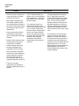
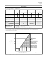
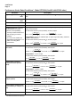
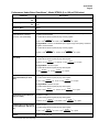
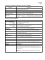
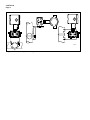
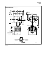
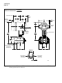
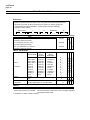
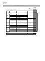
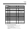
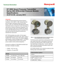
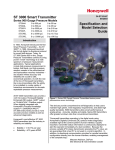
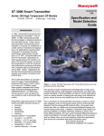
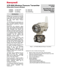
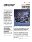
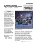
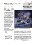
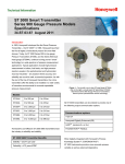
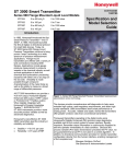
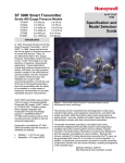
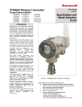
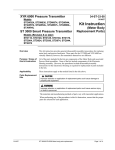
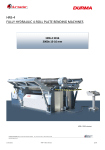
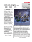
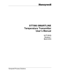
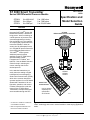
34-ST-03-65 10/99 ST 3000 Smart Transmitter Series 900 Differential Pressure Models STD924 STD930 STD974 0 to 400 inH2O 0 to 100 psi 0 to 3000 psi Specification and Model Selection Guide 0 to 1,000 mbar 0 to 7,000 mbar 0 to 210,000 mbar Function Honeywell’s ST 3000® Series 900 Differential Pressure Transmitters bring proven “smart” technology to a wide spectrum of pressure measurement applications including flow and liquid level. They transmit an output signal proportional to the measured variable in either an analog 4 to 20 milliampere format or in a digital DE protocol format for direct digital integration with our TDC 3000®X control system. Additional protocol options available for the ST 3000 Series 900 transmitters include 1 FOUNDATION™ Fieldbus and 2 HART® . See the Model Selection Guide for help in selecting the correct ordering code for the desired protocol. In the standard transmitter you easily select the analog or digital transmission format through the Smart Field Communicator (SFC®) which is the common hand-held operator interface for our DE-based Smartline® Transmitters. All configuration, operation, and communications functions are under the control of the ST 3000 Smart Transmitter’s microprocessor and are accessible through the SFC. ¹ FOUNDATION™ Fieldbus is a trademark of the Fieldbus Foundation. ² HART is a registered trademark of the Hart Communication Foundation ST 3000 Differential Pressure Transmitter H on eyw ell ... o. I NG G N RK TA C WO SF Models: STD924 STD930 STD974 ITS UN CO NF ID V LR 0% DA MP V UR 0% 10 NU ME M ITE XT NE T SE TOU T PU R-R CO T EC EV PR 9 8 6 7 5 4 Smart Field Communicator 3 2 1 A ST T 0 SP . R C L O) (N AN SH Can be ordered separately see specification 34-ST-03-55 +/ IF R TE EN ES) (Y T M/ NU HA P AL 24256 Figure 1 —Series 900 Differential Pressure Transmitters feature proven “smart” technology and come in several models to meet varying application needs. Industrial Automation and Control, 16404 N. Black Canyon Highway, Phoenix, AZ 85023 Printed in U.S.A.■ © Copyright 1998 — Honeywell Inc. 34-ST-03-65 Page 2 Features • Choice of linear or square root output conformity is a simple configuration selection. • Direct digital integration with TDC 3000X system provides local measurement accuracy to the system level without adding typical A/D and D/A converter inaccuracies. • Unique piezoresistive sensor automatically compensates input for temperature and static pressure. • Added “smart” features include configuring lower and upper range values, simulating accurate analog output, and selecting preprogrammed engineering units for display. • Smart transmitter capabilities with local or remote interfacing means significant manpower efficiency improvements in commissioning, start-up, and ongoing maintenance functions. • Local zero and span adjustments are available for alternate adjustment method, if desired. Description The ST 3000 transmitter can replace any 4 to 20 milliampere output transmitter in use today, and operates over a standard two-wire system. The measuring means is a piezoresistive sensor which actually contains three sensors in one. It contains a differential pressure sensor, a temperature sensor, and a static pressure sensor. Microprocessor-based electronics provide higher spanturndown ratio, improved temperature and pressure compensation, and improved accuracy. Like other Smartline Transmitters, the ST 3000 features two-way communication between the operator and the transmitter through our SFC. You can connect the SFC anywhere that you can access the transmitter signal lines, and it provides the capabilities of transmitter adjustments and diagnostics from remote locations, such as the control room. The transmitter’s meter body and electronics housing resist shock, vibration, corrosion, and moisture. The electronics housing contains a compartment for the single-board electronics, which is isolated from an integral junction box. The singleboard electronics is replaceable and interchangeable with any other ST 3000 Series 900 or Series 100e model transmitter. 34-ST-03-65 Page 3 Specifications Operating Conditions – All Models Parameter Reference Condition (at zero static) Rated Condition Operative Limits Transportation and Storage °C °F °C °F °C Ambient Temperature 25 ±1 77 ±2 -40 to 85 -40 to 185 -40 to 85 -40 to 185 -55 to 125 -67 to 257 Meter Body Temperature 25 ±1 77 ±2 -40 to 110* -40 to 230* -40 to 125 -40 to 257 -55 to 125 -67 to 257 Humidity %RH Overpressure 10 to 55 0 to 100 0 to 100 0 0 3000** 210** 3000** 210** Atmospheric Atmospheric 25 13 2 (short term†) 1 (short term† psi bar Vacuum Region - Minimum Pressure mmHg absolute inH2O absolute Supply Voltage, Current, and Load Resistance °F °C °F 0 to 100 Voltage Range: 10.8 to 42.4 Vdc at terminals Current Range: 3.0 to 21.8 mA Load Resistance: 0 to 1440 ohms (as shown in Figure 2) * For CTFE fill fluid, the rating is –15 to 70°C (5 to 158°F) ** For models STD924 and STD930, static limit is 2000 psi (140 bar) for temperatures below –15°C (5°F). Overpressure is 3K. † Short term equals 2 hours at 70°C (158°F) 1440 1200 Loop Resistance (ohms) = Operating Area NOTE: A minimum of 250 0hms of loop resistance is necessary to support communications. Loop resistance equals barrier resistance plus wire resistance plus receiver resistance. Also 45 volt operation is permitted if not an intrinsically safe installation. 800 650 450 250 0 10.8 16.28 20.63 25 28.3 37.0 Operating Voltage (Vdc) Figure 2—Supply voltage and loop resistance chart 42.4 21012 34-ST-03-65 Page 4 Performance Under Rated Conditions* - Model STD924 (0 to 400 inH2O/1000 mbar) Parameter Description Upper Range Limit inH2O mbar 400 (39.2°F/4°C is standard reference temperature for inH2O range.) 1000 Minimum Span inH2O mbar 10 25 Note: Recommended minimum span in square root mode is 20 inH2O (50 mbar). Turndown Ratio 40 to 1 Zero Elevation and Suppression –5 to +100% URL. Accuracy (Reference – Includes combined effects of linearity, hysteresis, and repeatability) In Analog Mode: ±0.10% of calibrated span or upper range value (URV), whichever is greater, terminal based. For URV below reference point (25 inH 2O), accuracy equals: • Accuracy includes residual error after averaging successive readings. 25 inH2O 62 mbar ±0.05 + 0.05 span inH O or ±0.05 + 0.05 span mbar in % span 2 In Digital Mode: ±0.075% of calibrated span or upper range value (URV), whichever is greater, terminal based. For URV below reference point (25 inH2O), accuracy equals: • For FOUNDATION Fieldbus use Digital Mode specifications. For HART use Analog Mode specifications. Zero Temperature Effect per 28°C (50°F) 25 inH2O 62 mbar ±0.025 + 0.05 span inH O or ±0.025 + 0.05 span mbar in % span 2 In Analog Mode: ±0.1625% of span. For URV below reference point (50 inH 2O), effect equals: 50 inH2O 125 mbar ±0.0125 + 0.15 span inH O or ±0.0125 + 0.15 span mbar in % span 2 In Digital Mode: ±0.15% of span. For URV below reference point (50 inH 2O), effect equals: 50 inH2O 125 mbar ±0.15 span inH O or ±0.15 span mbar in % span 2 Combined Zero and Span Temperature Effect per 28°C (50°F) In Analog Mode: ±0.25% of span. For URV below reference point (50 inH2O), effect equals: 50 inH2O 125 mbar ±0.10 + 0.15 span inH O or ±0.10 + 0.15 span mbar in % span 2 In Digital Mode: ±0.225% of span. For URV below reference point (50 inH2O), effect equals: 50 inH2O 125 mbar ±0.075 + 0.15 span inH O or ±0.075 + 0.15 span mbar in % span 2 Zero Static Pressure Effect per 1000 psi (70 bar) ±0.1625% of span. For URV below reference point (50 inH2O), effect equals: 50 inH2O 125 mbar ±0.0125 + 0.15 span inH O or ±0.0125 + 0.15 span mbar in % span 2 Combined Zero and Span Static Pressure Effect per 1000 psi (70 bar) ±0.30% of span. For URV below reference point (50 inH2O), effect equals: Stability ±0.03% of URL per year 50 inH2O 125 mbar ±0.15 + 0.15 span inH O or ±0.15 + 0.15 span mbar in % span 2 * Performance specifications are based on reference conditions of 25°C (77°F), zero (0) static pressure, 10 to 55% RH, and 316L Stainless Steel barrier diaphragm. 34-ST-03-65 Page 5 Performance Under Rated Conditions* - Model STD930 (0 to 100 psi/7000 mbar) Parameter Description Upper Range Limit psi bar 100 7 Minimum Span psi bar 5 0.35 Turndown Ratio 20 to 1 Zero Elevation and Suppression –5 to +100% URL. Accuracy (Reference – Includes combined effects of linearity, hysteresis, and repeatability) In Analog Mode: ±0.10% of calibrated span or upper range value (URV), whichever is greater, terminal based. For URV below reference point (20 psi), accuracy equals: • 20 psi 1.4 bar ±0.05 + 0.05 span psi or ±0.05 + 0.05 span bar in % span • In Digital Mode: ±0.075% of calibrated span or upper range value (URV), whichever is greater, terminal based. For URV below reference point (20 psi), accuracy equals: 20 psi 1.4 bar ±0.025 + 0.05 span psi or ±0.025 + 0.05 span bar in % span Zero Temperature Effect per 28°C (50°F) In Analog Mode: ±0.1625% of span. For URV below reference point (30 psi), effect equals: 30 psi 2 bar ±0.0125 + 0.15 span psi or ±0.0125 + 0.15 span bar in % span In Digital Mode: ±0.15% of span. For URV below reference point (30 psi), effect equals: 30 psi 2 bar ±0.15 span psi or ±0.15 span bar in % span Combined Zero and Span Temperature Effect per 28°C (50°F) In Analog Mode: ±0.25% of span. For URV below reference point (30 psi), effect equals: 30 psi 2 bar ±0.10 + 0.15 span psi or ±0.10 + 0.15 span bar in % span In Digital Mode: ±0.225% of span. For URV below reference point (30 psi), effect equals: 30 psi 2 bar ±0.075 + 0.15 span psi or ±0.075 + 0.15 span bar in % span Zero Static Pressure Effect per 1000 psi (70 bar) ±0.1625% of span. For URV below reference point (30 psi), effect equals: 30 psi 2 bar ±0.0125 + 0.15 span psi or ±0.0125 + 0.15 span bar in % span Combined Zero and Span Static Pressure Effect per 1000 psi (70 bar) ±0.30% of span. For URV below reference point (30 psi), effect equals: 30 psi 2 bar ±0.15 + 0.15 span psi or ±0.15 + 0.15 span bar in % span Stability ±0.04% of URL per year * Performance specifications are based on reference conditions of 25°C (77°F), zero (0) static pressure, 10 to 55% RH, and 316L Stainless Steel barrier diaphragm. 34-ST-03-65 Page 6 Performance Under Rated Conditions* - Model STD974 (0 to 3000 psi/210 bar) Parameter Description Upper Range Limit psi bar 3000 210 Minimum Span psi bar 100 7 Turndown Ratio 30 to 1 Zero Elevation and Suppression –0.6 and +100% URL. Accuracy (Reference – Includes combined effects of linearity, hysteresis, and repeatability) In Analog Mode: ±0.2% of calibrated span or upper range value (URV), whichever is greater, terminal based. For URV below reference point (300 psi), accuracy equals: • Accuracy includes residual error after averaging successive readings. 300 psi 21 bar ±0.05 + 0.15 span psi or ±0.05+ 0.15 span bar in % span • For FOUNDATION Fieldbus use Digital Mode specifications. For HART use Analog Mode specifications. Zero Temperature Effect per 28°C (50°F) In Digital Mode: ±0.175% of calibrated span or upper range value (URV), whichever is greater, terminal based. For URV below reference point (300 psi), accuracy equals: 300 psi 21 bar ±0.025 + 0.15 span psi or ±0.025+ 0.15 span bar in % span In Analog Mode: ±0.2125% of span. For URV below reference point (500 psi), effect equals: 500 psi 35 bar ±0.0125 + 0.20 span psi or ±0.0125 + 0.20 span bar in % span In Digital Mode: ±0.20% of span. For URV below reference point (500 psi), effect equals: 500 psi 35 bar ±0.20 span psi or ±0.20 span bar in % span Combined Zero and Span Temperature Effect per 28°C (50°F) In Analog Mode: ±0.325% of span. For URV below reference point (500 psi), effect equals: 500 psi 35 bar ±0.125 + 0.20 span psi or ±0.125 + 0.20 span bar in % span In Digital Mode: ±0.30% of span. For URV below reference point (500 psi), effect equals: 500 psi 35 bar ±0.10 + 0.20 span psi or ±0.10 + 0.20 span bar in % span Zero Static Pressure Effect per 1000 psi (70 bar) ±0.1625% of span. For URV below reference point (500 psi), effect equals: 500 psi 35 bar ±0.0125 + 0.15 span psi or ±0.0125 + 0.15 span bar in % span Combined Zero and Span Static Pressure Effect per 1000 psi (70 bar) ±0.30% of span. For URV below reference point (500 psi), effect equals: 500 psi 35 bar ±0.15 + 0.15 span psi or ±0.15 + 0.15 span bar in % span Stability ±0.03% of URL per year * Performance specifications are based on reference conditions of 25°C (77°F), zero (0) static pressure, 10 to 55% RH, and 316L Stainless Steel barrier diaphragm. 34-ST-03-65 Page 7 Performance Under Rated Conditions - General for all Models Parameter Description Output (two-wire) Analog 4 to 20 mA or DE digital communications mode. Options available for FOUNDATION Fieldbus and HART protocol. Supply Voltage Effect 0.005% span per volt. Damping Time Constant Adjustable from 0 to 32 seconds digital damping. CE Conformity (Europe) 89/336/EEC, Electromagnetic Compatibility (EMC) Directive. Lightning Protection Option Leakage Current: 10 microamps max. @ 42.4 VDC, 93°C (Code “LP”) Impulse Rating: (rise/decay) 10/20 µ sec. 5,000 Amps (50 strikes) 10,000 Amps (20 strikes) 10/1000 µ sec. 250 Amps (1000 strikes) 500 Amps (400 strikes) Physical and Approval Bodies Parameter Description Barrier Diaphragms Material STD924, STD930 STD974 316L SS, Hastelloy C-276, Monel, Tantalum 316L SS, Hastelloy C-276 Process Head Material STD924, STD930 STD974 316 SS, Carbon Steel (zinc-plated), Monel, Hastelloy 316 SS, Carbon Steel (zinc-plated), Hastelloy Head Gaskets Teflon, Viton (Only with 316L SS or Monel barrier diaphragms) Meter Body Bolting Carbon Steel (Zinc plated, standard) or A286 SS (NACE) bolts and 302/304 SS (NACE) nuts for heads and 316 SS (NACE) bolts for adapters (standard option). Mounting Bracket Carbon Steel (Zinc-plated) or Stainless Steel angle bracket or Carbon Steel flat bracket available (standard options). Fill Fluid Silicone DC 200 oil or CTFE (Chlorotrifluoroethylene) Electronic Housing Epoxy-Polyester hybrid paint. Low Copper-Aluminum. Meets NEMA 4X (watertight) and NEMA 7 (explosionproof). Stainless steel optional. Process Connections 1/4-inch NPT; 1/2-inch NPT with adapter, standard option; DIN. Wiring Accepts up to 16 AWG (1.5 mm diameter). Mounting Can be mounted in virtually any position using the standard mounting bracket. Bracket is designed to mount on 2-inch (50 mm) vertical or horizontal pipe. See Figure 3. Dimensions See Figures 4 and 5. Net Weight 9 pounds (4.1 Kg) Approval Bodies Approved as explosionproof and intrinsically safe for use in Class I, Division 1, Groups A, B, C, D locations, and nonincendive for Class I, Division 2, Groups A, B, C, D locations. Approved EEx ia IIC T5 and EEx d IIC T6 per CENELEC standards; and Ex N II T5 per BS 6941. Series 900 with HC (HART) compatibility is self-certified for Zone 2, T5, maximum 42V/22 mA. 34-ST-03-65 Page 8 24264 Figure 3—Examples of typical mounting positions 34-ST-03-65 Page 9 Reference Dimensions: With Smart meter millimeters inches 82.9 3.26 Removal Clearance for All Caps 45.7 1.8 94.9 3.74 53.1 2.09 65.1 2.56 Without meter Without meter 3.6 0.14 Plug 135 5.32 55.3 2.18 23.5 .925 214 8.43 Optional Meters Optional external ground 125.2 4.93 Rotational Lock 67 2.64 Optional Adapter for 1/2-inch NPT See Detail "A" 53.9 2.12 32.5 1.28 93.6 3.69 129 5.08 Detail A 53.9 2.12 High Pressure Connection 1/2-inch NPT Low Pressure Connection 1/2-inch NPT 53.9 2.12 1.5 0.06 24258 Figure 4—Typical models STD924 and STD930-A, B, E, F, J (SS, Hastelloy C) mounting dimensions for reference. 34-ST-03-65 Page 10 Reference Dimensions: With Smart meter millimeters inches 82.9 3.26 Removal 45.7 Clearance 1.8 for All Caps 94.9 3.74 53.1 2.09 65.1 2.56 Without meter Without meter With Analog meter 3.6 Plug 0.14 135 5.32 55.3 2.18 Optional meters 23.5 .925 Optional external ground 266.6 10.5 Rotational lock 168.8 6.65 85 3.35 SQ Optional Adapter for 1/2-inch NPT See Detail "A" Plug 32.5 1.28 100 3.94 53.9 2.12 121.4 4.78 Detail A 53.9 2.12 High Pressure Connection 1/2-inch NPT Low Pressure Connection 1/2-inch NPT 53.9 2.12 1.5 0.06 24259 Figure 5—Typical models STD924 and STD930-C, D, G, H, K, L (Monel, Tantalum), and model STD974 mounting dimensions for reference 34-ST-03-65 Page 11 Options Ordering Information Mounting Bracket Tagging (Option TG) The angle mounting bracket is available in either zinc-plated carbon steel or stainless steel and is suitable for horizontal or vertical mounting on a two inch (50 millimeter) pipe, as well as wall mounting. An optional flat mounting bracket is also available in carbon steel for two inch (50 millimeter) pipe mounting. Up to 30 characters can be added on the stainless steel nameplate In the U.S.: mounted on the transmitter’s Honeywell electronics housing at no extra cost. Industrial Automation & Control Note that a separate nameplate on 16404 N. Black Canyon Highway the meter body contains the serial Phoenix, AZ 85023 number and body-related data. A 1-800-288-7491 stainless steel wired on tag with additional data of up to 4 lines of 28 In Canada: characters is also available. The The Honeywell Centre number of characters for tagging 155 Gordon Baker Rd. includes spaces. North York, Ontario M2H 3N7 Transmitter Configuration 1-800-461-0013 (Option TC) The factory can configure the In Latin America: transmitter linear/square root Honeywell Inc. extraction, damping time, LRV, 480 Sawgrass Corporate Parkway, URV and mode (analog/digital) and Suite 200 enter an ID tag of up to eight Sunrise, FL 33325 characters and scratchpad (954) 845-2600 information as specified. Indicating Meter Two integral meter options are available. An analog meter (option ME) is available with a 0 to 100% linear scale. The Smart Meter (option SM) provides an LCD display for both analog and digital output and can be configured to display pressure in pre-selected engineering units. Lightning Protection A terminal block is available with circuitry that protects the transmitter from transient surges induced by nearby lightning strikes. HART Protocol Compatibility (Option HC) An optional electronics module is available for the Series 900 that provides HART Protocol compatibility. Transmitters with the HART Option are compatible with the AMS System. (Contact your AMS Supplier if an upgrade is required.) Custom Calibration and ID in Memory (Option CC) The factory can calibrate any range within the scope of the transmitter’s range and enter an ID tag of up to eight characters in the transmitter’s memory. FOUNDATION Fieldbus (Option FF) Equips transmitter with FF protocol for use in 31.25 kbit/s FF networks. See document 34-ST-03-72 for additional information on ST 3000 Fieldbus transmitters. Configuration of the HART Option transmitter is accomplished using a Universal HART Communicator. For full functionality the communicator must contain the Honeywell Device Description (DD). Contact your nearest Honeywell office or distributor for further information regarding this option. Specifications are subject to change without notice. (Note that specifications may differ slightly for transmitters manufactured before October 30, 1995.) Contact your nearest Honeywell sales office, or In Europe: Honeywell PACE 1, Avenue du Bourget B-1140 Brussels, Belgium [32-2] 728-2111 In Asia: Honeywell Asia Pacific Inc. Room 3213-25 Sun Hung Kai Centre No. 30 Harbour Road Wanchai, Hong Kong 2829-8298 In the Pacific: Honeywell Limited 5 Thomas Holt Drive North Ryde NSW 2113 Australia (61 2) 9353 7000 Or, visit Honeywell on the World Wide Web at: http://www.honeywell.com 34-ST-03-65 Page 12 Model Selection Guide 34-ST-16-24 Instructions Select the desired Key Number. The arrow to the right marks the selection available. Make one selection from each table, I and II, using the column below the proper arrow. Select as many Table III options as desired (if no options are desired, specify 00). A dot denotes unrestricted availability. A letter denotes restricted availability. Restrictions follow Table IV. Key Number ______ I - ___ II - _____ III (Optional) - _ _, _ _ _ _ KEY NUMBER IV + XXXX Selection Span 0-10" to 0-400" H2O/0-25 to 0-1000 mbar Body Rating: 3000 psi (210 bar) 0-5 to 0-100 psi/0-0.34 to 0-7 bar Body Rating: 3000 psi (210 bar) 0-100 to 0-3000 psi/0-7 to 0-210 bar Body Rating: 3000 psi (210 bar) Availability STD924 STD930 STD974 TABLE I - METER BODY Wetted Process Heads Material of Construction Carbon Steel * Carbon Steel * Carbon Steel * Carbon Steel * 316 St. St. 316 St. St. 316 St. St. 316 St. St. Hastelloy C Hastelloy C Monel Vent/Drain Valves ** and Plugs Barrier Diaphragms 316 St. St. 316 St. St. 316 St. St. 316 St. St. 316 St. St. 316 St. St. 316 St. St. 316 St. St. Hastelloy C Hastelloy C Monel 316 LSS Hastelloy C Monel Tantalum 316 LSS Hastelloy C Monel Tantalum Hastelloy C Tantalum Monel Fill Fluid Silicone CTFE Process Head Configuration 1/4" NPT 1/2" NPT with Adapter (on 1/4" NPT Head) TABLE II No Selection * Carbon Steel heads are zinc-plated. A__ B__ C__ D__ E__ F__ G__ H__ J__ K__ L__ v v v v v t t _1_ _2_ __A __H t 00000 Not recommended for water service due to hydrogen migration. Use Stainless Steel heads. ** Vent/Drains are Teflon coated for lubricity. 34-ST-03-65 Page 13 Model Selection Guide, continued Availability STD9 TABLE III - OPTIONS None Adapter Flange - 1/2" NPT St. Steel Adapter Flange - 1/2" NPT Hastelloy-C Adapter Flange - 1/2" NPT Monel Modified DIN Process Heads - 316SS Viton Head Gaskets (1/2" adapter gaskets are special) Mounting Bracket - Carbon Steel Mounting Bracket - ST. ST. Flat Mounting Bracket - Carbon Steel 316 ST.ST. Electronics Housing with M20 Conduit Connections 1/2" NPT to M20 316SS Conduit Adapter (BASEEFA EEx d IIC) 1/2" NPT to 3/4" NPT 316 SS Conduit Adapter Lightning Protection Analog Meter (0-100 Even 0-10 Square Root) Smart Meter Local Zero Local Zero and Span A286SS (NACE) Bolts and 302/304SS (NACE) Nuts for Heads and 316SS (NACE) Bolts for Adapters Stainless Steel Customer Wired-On Tag (4 lines, 28 characters per line, customer supplied information) Stainless Steel Customer Wired-On Tag (blank) Custom Calibration and I.D. in Memory Transmitter Configuration Write Protection Additional Warranty - 1 year Additional Warranty - 2 years Additional Warranty - 3 years Additional Warranty - 4 years Clean Transmitter for Oxygen or Chlorine Service with Certificate Over-Pressure Leak Test with F3392 Certificate Side Vent/Drain (End Vent Drain is standard) SS Center Vent Drain and Bushing Blind DIN SS Flanges Mounted with NACE Bolts Low Temperature - -50oC Ambient Limit Calibration Test Report and Certificate of Conformance (F3399) Certificate of Conformance (F3391) Certificate of Origin (F0195) NACE Certificate (F0198) HART® Protocol Compatible Electronics FOUNDATION Fieldbus Communications Selection 00 S2 T2 V2 DN VT MB SB FB SH A1 A2 LP ME SM LZ ZS CR 24 30 74 c c c w z c c c w z c c c w z b b m m m n n n u u u b b x s x s x s TG TB CC TC WP W1 W2 W3 W4 0X TP SV CV B2 LT F1 F3 F5 F7 HC FF b j j j g g y g g d d d b b o o o e e e r r r b 34-ST-03-65 Page 14 Model Selection Guide, continued Availability STD9 TABLE III - OPTIONS (continued) Approval Body Approval Type No hazardous location approvals Explosion Proof Factory Dust Ignition Proof Mutual Non-Incendive Intrinsically Safe CSA Explosion Proof Dust Ignition Proof Intrinsically Safe Zone 2 (Europe) Self-Declared per 94/9/EC (ATEX4) SA Intrinsically Safe (Australia) Non-Incendive Flame Proof Flame Proof LCIE Intrinsically Safe CENELEC Flame Proof Intrinsically Safe TABLE IV Factory Identification Selection 24 30 74 Location or Classification 9X Class I, Div. 1, Groups A,B,C,D Class II, III Div. 1, Groups E,F,G Class I, Div. 2, Groups A,B,C,D Class I, II, III, Div. 1, Groups A,B,C,D,E,F,G Class I, Div. 1, Groups B,C,D Class II, III, Div. 1, Groups E,F,G Class I, II, III, Div. 1, Groups A,B,C,D,E,F,G Ex II 3 GD T (1) X (1) T4 at Tamb. 93oC, T5 at Tamb. 80oC, T6 at Tamb. 65oC Ex ia IIC T4 Ex n IIC T6 (T4 with SM option) Ex d IIC T6 EEx d IIC T6 EEx ia IIC T5 EEx d IIC T6 EEx ia IIC T5 1C b 2J 3N 4H a a a 3A f f f 3D 3S XXXX h k 34-ST-03-65 Page 15 Model Selection Guide, continued RESTRICTIONS Restriction Letter a b c d e f g h j k m n o r s t u v w x y z Note: Table Available Only With Not Available With Selection Table Selection Approval Body pending Select only one option from this group __H I I III lll III E _ A, F _ A, G _ A, H _ A DN 1C, 2J, 3D, 3N, 9X HC I I _2_ C _ _, G _ _, L _ _ III III III I III I STD930-C _ _, G _ _, L _ _ K _ _, L _ _ includes side vent no price add C _ _, G _ _, L _ _ III III ZS, 1C, 2J 1C, 2J III III TC, ME FF, ME I I CR or B2 Select from Table III S2, T2, V2 1C, 2J Includes side vent drain - no price add E _ A, F _ A, G _ A, H _ A III FF, SM I III I SV J_ _, includes side vent, no price add DN B _ _, D _ _, F _ _, H _ _, J _ _, K _ _ See 13:ST-27 for Published Specials with pricing. See 13:ST-29 and User’s Manual for part numbers. See 13:ST-OE-9 for OMS Order Entry Information including TC, manuals, certificates, drawings and SPINS. See 13:ST-OD-1 for tagging, ID, Transmitter Configuration (TC) and calibration including factory default values. To request a quotation for a non-published "special", fax RFQ to Marketing Applications. 34-ST-03-65 Page 16 Industrial Automation and Control Honeywell Inc. 16404 North Black Canyon Highway Phoenix, Arizona 85023-3099