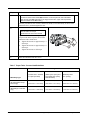
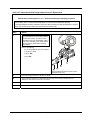
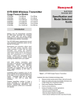
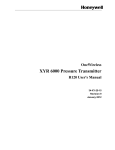
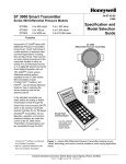
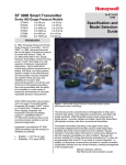
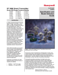
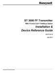
1
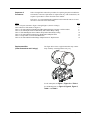
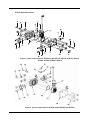
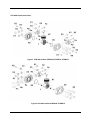
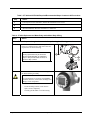
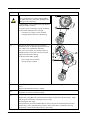
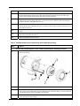
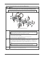
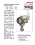
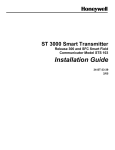
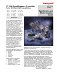
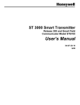
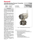
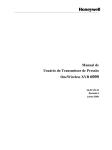
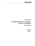
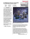
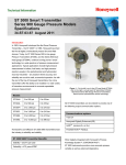
XYR 6000 Pressure Transmitter
Models
STDW924, STDW930, STDW974, STGW944,
STGW974, STGW94L, STGW97L, STGW98L,
STAW94L
ST 3000 Smart Pressure Transmitter
34-ST-33-50
9/14/07
Kit Instruction
(Meter Body
Replacement Parts)
Models (Revision S or later)
STD110, STD120, STD125, STD130, STD170,
STD904, STD924, STD930, STD974, STG944,
STG974
Overview
This kit instruction provides general (disassembly/assembly) procedures for replacing
meter body and process head parts. These parts for the ST 3000 and XYR 6000 are
virtually identical, however, the transmitters themselves are different.
Purpose / Scope of
this kit Instruction
All of the parts included in the kits are components of the Meter Body and associated
Process Head assemblies. None of the kits include components of the Electronic
Housing assembly. However, the procedures include disassembly/assembly
instructions for the Electronics Housing as required for replacement of parts included
in the kits.
Applicability
These instructions apply to the models listed in the title above.
Parts Replacement
Kits
Improper selection or application of replacement parts could cause damage to
property and equipment.
Improper selection or application of replacement parts could cause serious injury
or death to personnel.
The materials and manufacturing methods of parts vary with transmitter applications.
When performing any of the procedures in this kit Instruction, ensure that the proper
parts are selected for each application.
9/14/07
ST 3000/XYR 6000 Meter body parts replacement
Page 1 of 14
Required
publications
For ST 3000 parts see Figure 1, Figure 2 and Table 1.
Note that the parts listed do not include the suffix (“tab number”, for example, -001)
that specifies applicability.
For detailed parts lists, refer to the model selection guide and the following
publications.
Manual #
Addendum for Model
Publication Title
STD110
STD110
STD120
STD125
STD130
STD170
STD904
STD924
STD930
STD974
STG944
STG974
34-ST-25-14
34-ST-99-18
34-ST-99-22
ST 3000 Smart Transmitter, Release
300 and Smart Field communicator
Model STS103 User Manual
34-ST-25-15
34-ST-99-19
34-ST-99-23
ST 3000 FF Transmitter, with
Foundation Fieldbus Option
Installation and Device Reference
Guide
34-ST-25-17
34-ST-99-20
34-ST-99-24
ST 3000 Smart Transmitter, Release
300 with HART Communications
Option, STS103
34-ST-33-39
34-ST-99-21
34-ST-99-25
ST 3000 Smart Transmitter, Release
300 and Smart Field communicator
Model STS103 Installation Guide
For XYR 6000 parts see Figure 3, Figure 4, Figure 5, Table 1 and Table 2.
For detailed XYR 6000 parts list see the following publication.
Page 2 of 14
Manual #
Addendum for Model
Publication Title
34-XY-25-15
n/a
OneWireless XYR 6000 Pressure
Transmitter User's Manual
n/a
ST 3000/XYR 6000 Meter body parts replacement
9/14/07
Sequence of
Procedures
Table 3 through Table 8 describe procedures for replacing the parts included in the
associated kit. Because requirements for replacement vary with circumstances, the
sequence of procedures is at the discretion of the installer.
In all cases, we recommend that the transmitter be disconnected from service and
moved to a clean area before disassembly.
Table
Page
6
7
8
8
10
12
13
14
Table 1 Kit parts common to Figure 1 through Figure 4 (Generic Listing*)
Table 2 Parts for XYR 6000 (see Figure 5)
Table 3 ST 3000 and XYR 6000 Required/Recommended Steps Common to All Procedures
Table 4 ST 3000 Replacement of Meter Body and/or Meter Body O-Ring
Table 5 XYR 6000 Replacement of Meter Body and/or Meter Body O-Ring
Table 6 ST 3000 and XYR 6000 Process Head Removal/Replacement
Table 7 Torque Table - Process Head Bolts/Nuts
Table 8 ST 3000 and XYR 6000 Flange Adapter Removal / Replacement
Replacement Kits
(Parts Illustrations and Listings)
The figure below shows a typical transmitter atop a meter
body assembly. Actual appearance may vary.
For ST 3000 parts see Figure 1, Figure 2 and Table 1.
For XYR 6000 parts see Figure 3, Figure 4, Figure 5,
Table 1 and Table 2.
9/14/07
ST 3000/XYR 6000 Meter body parts replacement
Page 3 of 14
ST 3000 Replacement Parts
Figure 1 Typical construction for ST3000 models STD110, STD120, STD130, STD170,
STD904, STD924, STD930, STD974
Figure 2 Typical construction for ST3000 models STG944 and STG974
Page 4 of 14
ST 3000/XYR 6000 Meter body parts replacement
9/14/07
XYR 6000 Replacement Parts
Figure 3 XYR 6000 models STDW924, STDW930, STDW974
Figure 4 XYR 6000 models STGW944, STGW974
9/14/07
ST 3000/XYR 6000 Meter body parts replacement
Page 5 of 14
Table 1 Kit parts common to Figure 1 through Figure 4 (Generic Listing*)
Key
Number
Description*
Quantity
Per kit
51452864* Process Head kit (includes the following items)
Pipe Plug
K1
Vent Plug
K2
Vent Bushing
K3
Process Head
K5
Gasket, Process Head
K6
Gasket, Adapter
Ka
2
1
1
1
1
1
51452951* Reference Head kit (includes the following items)
Carbon Steel Blind Reference Head
K9
316 SS Blind Reference Head (“HR” Option)
K9
1
1
51452865* Meterbody Gasket kit (includes the following items)
Gasket, Process Head
K6
Gasket, Flange Adapter
Ka
O-ring, meterbody to Electronics Housing
K7
6
6
3
51452866* Bolts & Nuts kit (includes the following items)
Bolt, Hex head, 7/16-20 UNF x 1.50" lg (Flange Adapter)
Kc
Nut, Hex, 7/16-14UNC (Process Head)
K4
Bolt, Hex, 7/16-14UNC x 3.25" lg (Process Head)
K8
4
4
4
51452867* Flange Adapter kit (includes the following items)
Gasket, Flange Adapter
Ka
Flange Adapter
Kb
Bolt, Hex, 7/16-20 UNF x 1.5" Lg (Flange Adapter)
Kc
2 or 1
2 or 1
4 or 2
51452868* Gasket kit (includes the following items)
Gasket, Process Head, PTFE
K6
(or)
Gasket, Process Head, Viton
K6
(or)
Gasket, Process Head, Graphite (use only as
K6
replacement of existing graphite gasket)
(or)
Gasket, Flange Adapter, PTFE
Ka
(or)
Gasket, Flange Adapter, Viton
Ka
(or)
Gasket, Flange Adapter, Graphite (use only as
Ka
replacement of existing graphite gasket)
12 (pack)
6 (pack)
6 (pack)
6 (pack)
6 (pack)
6 (pack)
*Identifications and descriptions of parts vary with manufacturing materials and methods for specific
applications. For detailed parts list refer to the publications for your transmitter. See page 2.
Page 6 of 14
ST 3000/XYR 6000 Meter body parts replacement
9/14/07
Figure 5 XYR 6000 models STGW94L, STGW97L, STGW98L, STAW94L
Table 2 Parts for XYR 6000 (see Figure 5)
Key
No.
1
K7
9/14/07
Part Number
Description
Specify complete
model number from
nameplate
Meter Body replacement kit includes:
30757503-001
Electronics enclosure seals kit for LGP/LAP models. Kit includes:
Meter body
Qty/
Unit
1
……..…….……………
O-ring for transmitter end caps
6
…………………………
O-ring, meter body to electronics housing
3
ST 3000/XYR 6000 Meter body parts replacement
Page 7 of 14
Table 3 ST 3000 and XYR 6000 Required/Recommended Steps Common to All Procedures
Step
Action
1
Turn off power to the transmitter, and take the transmitter out of service.
2
Disconnect all mechanical and electrical connections.
3
(Recommendation): Move the transmitter to a clean area.
Table 4 ST 3000 Replacement of Meter Body and/or Meter Body O-Ring
Step
Action
Perform the procedure given in Table 3 before performing the following procedure.
1
Loosen the lock set screw in the end-cap, item 1.
Unscrew (counterclockwise) and remove the end
cap from the electronics housing.
Note:
O-Ring replacement may be done with
process heads attached, as indicated at
right, or with process heads removed, as
shown in Step 3, below.
2
If a Smart Meter is included, remove it along with
the Printed Wiring Assembly.
CAUTION
Use a ground strap or an ionizer when handling
the PWA; otherwise, electrostatic discharges can
damage circuit components.
Page 8 of 14
−
On the mounting bracket, loosen the two
captive screws completely.
−
Carefully pull the PWA out of the housing.
ST 3000/XYR 6000 Meter body parts replacement
9/14/07
Step
Action
3
CAUTION
Use a ground strap or an ionizer when handling
the PWA; otherwise, electrostatic discharges can
damage circuit components.
If a Smart Meter is not included, remove the Printed
Wiring Assembly as follows.
To ensure correct re-assembly, note the orientation
of the bracket indicated in item 1 at right.
4
−
Loosen the two (captive) screws (item 2).
−
Carefully pull the PWA out of the housing.
Note the placement of the flex tape connection
behind the board. It should be replaced in the same
way when you re-assemble the transmitter.
For correct re-assembly, also note the position of
the PWA relative to the captive screws (item 2 at
right) in the Electronics housing.
At the back of the PWA, unplug:
5
-
power wiring from J1 (item 1)
-
flex tape from J3 (item 3).
On the outside neck portion of the meter body of the electronics housing, loosen the lock set
screw.
(Refer to the illustration in Step 1, item 2).
6
Using care not to twist or snag the flex tape, carefully unscrew (counterclockwise) the Meter Body
and remove it from the electronics housing.
7
If replacing the O-ring only:
Replace the O-ring (K7; refer to the illustration in Step 1) on the stem of the meter body. Apply
silicone grease such as Dow Corning #33 to the O-ring.
If replacing the meter body:
First perform the procedure in Table 6 (that is, remove the process heads and replace the head
gaskets (K6)). After completing that procedure, return to this table to continue the next step
(connection of electronic housing to the new meter body).
9/14/07
ST 3000/XYR 6000 Meter body parts replacement
Page 9 of 14
Step
Action
8
Feed the flex tape on the (new or existing) meter body through the neck of the housing, and screw
the Meter Body into the Electronics Housing until the bottom of the header portion of the center
section is approximately flush with the neck of the electronics housing.
9
Tighten the outside set-screw (refer to item 2 in the illustration in Step 1), and ensure that it is
seated in the slot on the meter body stem. Loosen the set-screw a half-turn, rotate the housing to
the desired position, and tighten the set-screw.
10
Refer to the illustration in Step 4.
Position the flex tape behind the board as it was before removal, and re-connect the flex tape to J3.
Re-connect power to J1.
11
Replace the PWA (and Smart Meter, if it is included) in the housing and re-insert the captive
screws.
12
Lubricate the O-ring for the end-cap with silicone grease such and Dow Corning #33 or
equivalent, and replace the end cap.
13
Place the transmitter back into service.
Table 5 XYR 6000 Replacement of Meter Body and/or Meter Body O-Ring
Step
Action
Perform the procedure given in Table 3 before performing the following procedure.
1
Loosen the M3 locking set screw on the transmitter’s display end-cap. See item 1. Unscrew and
remove the end cap.
2
1
4
3
2
2
Loosen the two screws on the display/sensor module. See items 2 in step 1 figure.
3
Disconnect meter body connector from J1 connector on the display/sensor module. See item 3 in
step 1 figure. Notice where this wire passes through a hole to the meter body; you will re-insert the
wire through this hole when re-attaching the meter body.
4
On the outside neck portion of the meter body of the electronics housing, loosen the lock set
screw. See item 4 in step 1 figure.
Page 10 of 14
ST 3000/XYR 6000 Meter body parts replacement
9/14/07
Step
Action
5
Unscrew the meter body from the transmitter. Remove the meter body, pulling the wire out
through the transmitter housing hole.
6
If replacing the O-ring only:
Replace the O-ring (K7; refer to the illustration in Step 1) on the stem of the meter body. Apply
silicone grease such as Dow Corning #33 to the O-ring.
If replacing the meter body:
First perform the procedure in Table 6 (that is, remove the process heads and replace the head
gaskets (K6)). After completing that procedure, return to this table to continue the next step
(connection of electronic housing to the new meter body).
7
Feed the connector on the (new or existing) meter body through the neck of the housing, up the
hole to the display. Screw the Meter Body into the Electronics Housing until the bottom of the
header portion of the center section is approximately flush with the neck of the electronics
housing.
9
Tighten the outside set-screw (item 4 in Step 1 figure), and ensure that it is seated in the slot on the
meter body stem. Loosen the set-screw a half-turn, rotate the housing to the desired position, and
tighten the set-screw.
10
Re-connect the meter body wire to J1 on the display/sensor module (Item 3 in step 1 figure ).
11
Install sensor module. Be sure to orient display/sensor module in the proper viewing orientation
before tightening two sensor compartment screws (item 2 in step 1 figure).
12
Lubricate the O-ring for the end-cap with silicone grease such and Dow Corning #33 or
equivalent, and replace the end cap.
13
Tighten the M3 locking set screw on the transmitter’s display end-cap. See item 1 in step 1 figure.
14
Place the transmitter back into service.
9/14/07
ST 3000/XYR 6000 Meter body parts replacement
Page 11 of 14
Table 6 ST 3000 and XYR 6000 Process Head Removal/Replacement
Step
Action
Perform the procedure given in Table 3 before performing the following procedure.
NOTE:
This procedure does not require that the Meter Body be removed from the Electronics Housing.
Note: actual appearance may vary
1
Caution:
To prevent damage to the diaphragm in the Meter Body, use extreme care when handling
the Meter Body (center section) or when placing it on any surface.
Loosen and remove the four nuts (K4).
Carefully separate the Process Head(s) (K5) from the Meter Body (item 1).
Discard the old Gaskets(s) (K6) and Process Head(s).
2
Apply sealant or PTFE Tape to the new bushings (K3) and pipe plugs (K1), and install into the
new Process Head. Tighten Bushings and Pipe Plugs to a torque of 58 +/- 2,7 N-m (43 +/- 2 LbFt). If Bushings (K3) require special orientation, then torque further up to an additional 180
degrees of rotation to desired orientation. Tighten Vent/Drain (K2) to 4,0 +/- 0,5 N-m (35 +/- 4
Lb-in).
Note:
If Flange Adapters (Kb) are to be attached, use the procedure given in Table 8.
3
If the old nuts and bolts for the Process Heads will be used, clean and then lubricate them.
If new nuts and bolts are to be installed, lubricate them.
Page 12 of 14
ST 3000/XYR 6000 Meter body parts replacement
9/14/07
Step
Action
Note:
4
The bolts for the Process Heads (K8) should be on the low-pressure side of the Meter
Body, and the nuts (K4) should be on the high-pressure side. (High- and low-pressure
sides are marked on the Meter Body.)
Carefully assemble the new Gasket(s) and Process head(s) to the Meter Body as shown in the
illustration above, and hand-tighten the nuts.
5
Note:
Refer to Table 7 for torque
specifications for the Process Heads.
Tighten the four nuts in three steps, using a
torque wrench in the sequence shown in the
illustration and as listed below.
7
a.
Tighten all four nuts to approximately 1/3
full torque.
b.
Tighten all four nuts to approximately 2/3
full torque.
c.
Tighten all four nuts to full torque.
Place the transmitter back into service.
Table 7 Torque Table - Process Head Bolts/Nuts
Bolt Type
51452557-001
5142557-002 and –003
51452557-004
(Carbon Steel - standard;
no option specified)
(NACE [“CR” option] and
Non-NACE [“SS” option]
Stainless Steel)
(B7M Alloy Steel
[“B7” option])
51451864XXXX
(All Transmitters except
Draft Range)
67,8 N•M +/- 3,4 N•M
56,9 N•M +/- 2,8 N•M
48,8 N•M +/- 2,4 N•M
(50.0 Lb-Ft +/- 2.5 Lb-Ft)
(42.0 Lb-Ft +/- 2.1 Lb-Ft)
(36.0 Lb-Ft +/- 1.8 Lb-Ft)
51451864XXX5
(Draft Range Transmitter
only)
20,3 N•M +/- 1,0 N•M
20,3 N•M +/- 1,0 N•M
20,3 N•M +/- 1,0 N•M
(15.0 Lb-Ft +/- 0.8 Lb-Ft)
(15.0 Lb-Ft +/- 0.8 Lb-Ft)
(15.0 Lb-Ft +/- 0.8 Lb-Ft)
Meterbody Type
9/14/07
ST 3000/XYR 6000 Meter body parts replacement
Page 13 of 14
Table 8 ST 3000 and XYR 6000 Flange Adapter Removal / Replacement
Perform the procedure given in Table 3 before performing the following procedure.
NOTE:
This procedure does not require that the Meter Body be removed from the Electronics Housing.
If the Flange Adapters are being replaced in conjunction with procedures for other kits parts (that is, Process
heads, etc), follow those procedures and incorporate the following steps.
Step
Action
Note:
The threaded hole in each Flange Adapter
is offset from center. To ensure correct
orientation when it is reassembled, make a
note of the orientation of the offset relative
to each Process Head before removing
any adapter.
1
Remove and discard:
-
the two bolts (Kc) that attach the Adapter
to the Process Head
-
Adapter (Kb)
-
Gasket (Ka)
Note: transmitter shown for context. Actual
appearance may vary.
2
Clean the mating surface(s) of the Process Heads.
3
Apply anti-seize lubricating compound to the new bolts, and carefully assemble the new
Adapter(s) and Gasket(s) to the Process Head(s).
4
Evenly torque the bolts to 47,5 N•M +/- 2,4 N•M (35 Lb-Ft +/- 1.8 Lb-Ft).
5
Place the transmitter back into service.
Page 14 of 14
ST 3000/XYR 6000 Meter body parts replacement
9/14/07