1
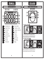
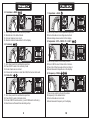
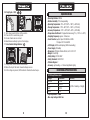
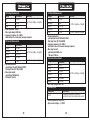
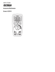
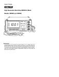
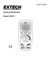
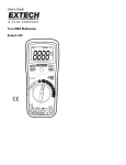
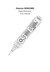
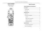
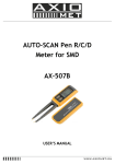
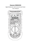
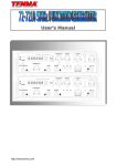
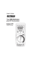
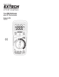
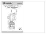
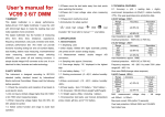
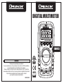
DIGITAL MULTIMETER
DDM453
/
DDM453
SERVICE
Thank you for purchasing our product!
As our customers are our top priority and we strive for 100% satisfaction,
we would appreciate your feedback on the product.
Please contact our customer service department at (310) 728-6220 or
at www.dawsontools.com if you have any questions regarding this product.
Our professional support team is always ready to answer
your enquiries and provide assistance.
00-05-3843
6
CAT.III
600V
LIMITED WARRANTY AND
LIMITATION OF LIABILITY
1.
This instrument from Dawson Tools Inc. will be free from defects in
workmanship and material for three years from the date of original
purchase. This warranty does not cover defects resulting from
damage caused by the user such as drops, neglect, misuse,
unauthorized alteration, usage outside of specified conditions,
contamination, or improper repair/maintenance. To receive service
on the instrument if it becomes necessary during the warranty period,
contact your nearest Dawson authorized service center at
(800) 898-6991 or visit www.DawsonTools.com to obtain a return
authorization (within the US only). A return authorization is necessary
before returning anyinstrument to Dawson; no service will be
provided without a return authorization. The user is responsible for
properly packing the unit and charges such as shipping, freight and
insurance charges. The extent of Dawson's liability is limited solely
to the repair/replacement of the instrument. The above warranty in
Its entirety is inclusive and no other warranties, written or oral, are
expressed or implied.
Out of the Box
Check the meter and accessories thoroughly before
using the meter. Contact your local distributor if the meter or any
components are damaged or malfunction.
Accessories
• Test leads
• User's manual
• 9V battery
• Type-K Thermocouple
x1 pair
x1
x1
x1
1
INTRODUCTION
DDM453 is a stable, safe, reliable compact digital handheld 6000 count
auto-ranging multimeter. This meter can measure AC/DC voltage, AC/DC
current, resistance, capacitance, frequency, duty cycle, temperature,
diodes and continuity. This meter is ideal for many situations, whether
you're a professional or causal user.
2.
WARNINGS
To avoid electric shock and injury or damage to the meter, observe the
following safety methods:
• Check the meter before use to make sure there was no damage during
transit.
• Check that the insulation on the test leads is not damaged and/or wires
are not exposed.
• If any faults or abnormalities are observed, the meter should not be used
and should be checked out prior to use.
• Never exceed the protection limit values indicated in specifications for
each range of measurement.
• Always be careful when working voltages above 60V DC or 30V AC rms,
keep fingers behind the probe barrier while measuring.
• Make sure the rotary switch is in the correct position before measurement.
• Never use the meter in an environment with explosive gas, vapor or dust.
• Always keep fingers behind probe barriers when making measurements.
• When connecting test leads to a circuit, connect the black test lead first,
then the red lead. Disconnect in the opposite order.
• Turn off power and discharge all capacitors first before measuring
resistance, continuity or diodes.
• Failure to follow safety guidelines could compromise the safety features
of this meter.
• Do not use the meter without the battery cover in place.
• Replace the batteries as soon as the low battery symbol appears
“
” to avoid
false reading that could lead to electric shock and injury.
• Remove test leads from all circuits before opening the battery cover.
2
SAFETY SYMBOLS
3.
Important safety information
Ground
AC(alternating current)
Double insulation protection
DC(direct current)
Fuse
DC/AC Voltage or Current
Compliance with EU regulations
FEATURE DETAILS
4.
1
4
2
DDM453
3
5
/
1.LCD Display
2.Hold/Backlight Button
Press “ ” to hold the current reading on the display. Press the button
again to release the hold. Hold “ ” to turn on the backlight.
Hold the button again to manually turn off the backlight.
3.Function Button
Press “FUNC” to switch between functions or between AC/DC current.
4.Frequency/Duty Cycle Button (Hz/%)
In AC voltage/current modes, press “Hz%” and the display will show the
frequency measurement. Press the button again to switch to duty cycle.
Press the button a third time to return to normal display.With the rotary
switch in the Hz/% position, the default mode is frequency. Press the
"Hz/%" button to show the duty cycle. Press the button again to switch
back to frequency display.
5.NCV Button
Hold the “NCV” button down in any mode and the meter will activate the
non-contact voltage detection. Move the top of the meter towards an
AC voltage source and the buzzer will sound and the NCV indicator
will light up if voltage is detected. Release the “NCV” button to stop
NCV detection.
6.Rotary Switch
7.Input Jack (all measurements; current below 600mA)
8.A Jack (current measurements between 600mA-10A only)
9.Common Jack (all measurements)
6
7
8
6
9
3
4
DISPLAY DESCRIPTION
5.
4
5
6
7
8
ROTARY SWITCH FUNCTIONS
6.
6
9
7
9
8
1
3
10
2
11
5
4
2
3
1
12
13
1. DC Voltage:<600V
1
Alternating Current
10
Duty Cycle Mode
2
Negative DC Value
10
Temperature in Celsius
Direct Current
10
Temperature in Fahrenheit
11
Resistance
3
4
Low Battery
5
Auto Power Off
11
Frequency
6
Auto Range Active
12
Capacitance
7
Data Hold
12
DC/AC Current
8
Diode Test
12
DC/AC Voltage
9
Continuity Test
13 Main Display
6
DDM453
/
1.Turn rotary switch to DC voltage position.
2.Connect leads across voltage source/load.
3.Read voltage measurement on the display.
2. AC Voltage:<600V
V
6
DDM453
/
1.Turn rotary switch to AC voltage position.
2.Connect leads across voltage source/load.
3.Read voltage measurement on the display.
5
6
4.2 AC Current (Medium):<600mA
3.1 DC Current (large):<10A
6
6
DDM453
DDM453
/
/
1.Turn rotary switch to mA position.
2.Press FUNC to select DC or AC current.
3.Connect leads in series to circuit.
4.Read current measurement on the display.
5.For frequency/duty cycle display, press Hz/%.
1.Turn rotary switch to A position.
2.Press FUNC to select DC or AC current.
3.Connect leads in series to circuit.
4.Read current measurement on the display.
3.2 AC Current (large):<10A
5.1 DC Current (Small):<6000µA
6
DDM453
/
6
DDM453
/
1.Turn rotary switch to A position.
2.Press FUNC to select DC or AC current.
3.Connect leads in series to circuit.
4.Read current measurement on the display.
1.Turn rotary switch to µA position.
2.Press FUNC to select DC or AC current.
3.Connect leads in series to circuit.
4.Read current measurement on the display.
5.2 AC Current (Small):<6000µA
4.1 DC Current (Medium):<600mA
6
DDM453
/
6
DDM453
/
1.Turn rotary switch to mA position.
2.Press FUNC to select DC or AC current.
3.Connect leads in series to circuit.
4.Read current measurement on the display.
7
1.Turn rotary switch to µ A position.
2.Press FUNC to select DC or AC current.
3.Connect leads in series to circuit.
4.Read current measurement on the display.
5.For frequency/duty cycle display, press Hz/%.
8
6.1 Resistance:<60MΩ
7. Capacitance: <60mF
6
6
DDM453
DDM453
/
1. Turn rotary switch to multifunction position.
2. Resistance is the default mode.
3. Connect leads across circuit.
4. Read resistance measurement on the display.
/
1.Turn rotary switch to the capacitance position.
2.Connect leads across voltage source/load.
3.Read voltage measurement on the display.
8. Temperature: -20°C~1000°C/-4°F~1832°F
6.2 Continuity:
6
DDM453
/
6
DDM453
/
1.Turn rotary switch to multifunction position
2.Press FUNC to switch to continuity mode
3.Connect leads across circuit.
4.If measured resistance is less than 50Ω, the buzzer will sound.
6.3 Diode Test:
1.Turn rotary switch to the TEMP position.
2.Press FUNC to select Fahrenheit or Celsius.
3.Touch tip of thermocouple to the test object.
4.Read measured temperature on the display.
9.1 Frequency:<10MHz
6
DDM453
/
6
DDM453
/
1.Turn rotary switch to multifunction position.
2.Press FUNC to switch to diode mode.
3.Connect INPUT lead to anode (+) and COM lead to cathode (-).
4.Read measured forward-biased voltage drop.
9
1.Turn rotary switch to the Hz/% position.
2.Frequency is the default mode.
3.Connect leads across circuit.
4.Read measured frequency on the display.
10
9.2 Duty Cycle:<99%
7.
6
DDM453
/
1.Turn rotary switch to the Hz/% position.
2.Press Hz/% to select duty cycle.
3.Connect leads across circuit.
4.Read measured duty cycle on the display.
11. Non-Contact Voltage Detector: NCV
DDM453
/
DD M4
53
/
1.In any mode, hold the NCV button down.
2.Move the top of the meter toward voltage source
3.If AC voltage is present, NCV indicator flashes/buzzer beeps.
Specifications
• Operating Altitude: 2000m
• Relative Humidity: 75% max operating
• Operating Temperature: 0°C~40°C/32°F~104°F (<80% RH)
• Storage Temperature: -10°C~60°C/14°F~140°F (<70% RH)
• Accuracy Temperature: -18°C~28°C/64°F~82°F (<80% RH)
• Temperature Coefficient: 0.1x(specified accuracy)/°C (<18°C or >28°C)
• Sampling Frequency: approx. 3 times/sec.
• Fuse Protection: µA/mA input: FF 600mA H 600V
10A input: FF 10A H 600V
• LCD Display: 6000 count display (5999 max reading)
• Power Supply: 9V battery
• Dimensions: 150mm×74mm×48mm / 6.3"×2.9"×1.9"
• Weight: 8.9oz/250g
• Safety Rating: CAT III 600V
• Safety Standards: IEC61010-1
• Pollution Degree: 2
• Accuracy: ±(of reading + # of least significant digits)
7.
ELECTRICAL SPECIFICATIONS
DC Voltage Measurement
Range
Resolution
600mV
6V
60V
600V
Accuracy
0.1mV
0.001V
0.01V
0.1V
±(0.5% of reading +2 digits)
• Input impedance: 10MΩ
• Max. input voltage: 600V rms
11
12
AC Voltage Measurement
Range
Resolution
6V
60V
600V
Accuracy
0.001V
0.01V
0.1V
±(1.0% of reading +5 digits)
• Input impedance: 10MΩ
• Max. input voltage: 600V rms
• Frequency response: 40~400Hz,
calibrated to rms of sine wave (average response)
DC Current Measurement
Range
Resolution
Accuracy
600µA
0.1µA
6000µA
1µA
±(1.0% of reading +5 digits)
60mA
0.01mA
600mA
0.1mA
±(2.0% of reading +8 digits)
10A
10mA
• Overload protection:
µA/mA input: Fuse(FF 600mA H 600V)
10A input: Fuse (FF 10A H 600V)
• Max. input current:
µA/mA input: 600mA rms
10A input: 10A rms
AC Current Measurement
Range
Resolution
Accuracy
600µA
0.1µA
6000µA
1µA
±(1.2% of reading +5 digits)
60mA
0.01mA
600mA
0.1mA
±(2.0% of reading +8 digits)
10A
10mA
• Overload protection:
µA/mA input: Fuse(FF 600mA H 600V)
10A input: Fuse (FF 10A H 600V)
• Frequency response: 40~400Hz,
calibrated to rms of sine wave (average response)
• Max. input current:
µA/mA input: 600mA rms
10A input: 10A rms
Resistance Measurement
Range
Resolution
600Ω
6kΩ
60kΩ
600kΩ
6MΩ
60MΩ
Accuracy
0.1Ω
0.001kΩ
0.01kΩ
0.1kΩ
0.001MΩ
0.01MΩ
±(0.7% of reading +3 digits)
• Max. input voltage: 600V rms
Continuity Test
Description
Resolution
If measured resistance is greater
0.1Ω
than 50Ω,the meter's buzzer will sound
• Overload protection: 600V rms
• Open circuit voltage: ~1.0V DC
13
14
Diode Test
Resolution
0.001V
Description
Display shows the forward-biased
voltage drop of the diode.
• Overload protection: 600V rms
• Open circuit voltage: ~3.2V DC
• Test current: ~ 1.0mA
Capacitance Measurement
Range
Resolution
10nF
100nF
1µF
10µF
100µF
1mF
10mF
100mF
Accuracy
0.01nF
0.1nF
1nF
10nF
100nF
1µF
10µF
10µF
±(4.0% of reading +5 digits)
• Max. input voltage: 600V rms
Frequency (AC voltage)
Range
Resolution
Accuracy
99.99Hz
0.01Hz
±(1.5% of reading +5 digits)
999.9Hz
0.1Hz
9.999kHz
0.001kHz
Reference only
>10kHz
0.01kHz
• Signal input range: ≥0.2V AC rms
(voltage input will increase as frequency increases)
• Input impedance: 10MΩ
• Max. input voltage: 600V rms
15
Frequency (AC current)
Range
Resolution
Accuracy
99.99Hz
0.01Hz
±(1.5% of reading +5 digits)
999.9Hz
0.1Hz
Reference only
>1kHz
0.001kHz
• Signal input range: µA: ≥60µA rms mA: ≥6mA rms A: ≥0.6A rms
(current input will increase as frequency increases)
• Max. input current: 10A rms
Frequency (Hz)
Range
9.999Hz
99.99Hz
999.9Hz
9.999kHz
99.99KHZ
999.9KHZ
9.999MHZ
Resolution
0.001Hz
0.01Hz
0.1Hz
0.001kHz
0.01kHz
0.1KHz
0.001MHz
Accuracy
±(1.5% of reading +5 digits)
• Signal input range:≥2V AC rms(voltage input will increase as
frequency increases)
• Max. input voltage: 600V rms
Duty Cycle
Range
Accuracy
Resolution
1 – 99%
0.1%
± 2.0%
• In current mode:
Signal input range: µA: ≥60µA rms mA: ≥6mA rms A: ≥0.6A rms
(current input will increase as frequency increases)
Max. input current: 10A rms
• In voltage mode:
Signal input range: ≥0.6V AC rms
(voltage input will increase as frequency increases)
Input impedance: 10MΩ
Max. input voltage: 600V rms
16
Temperature Measurement
Range
Resolution
Accuracy
±(2.0% of reading +2 digits)
±(2.0% of reading +4 digits)
10.
WARNINGS
-20°C~1000°C
1°C
-4°F~1832°F
1°F
• Overload protection: Fuse (F600mA/600V)
8.
9.
To avoid false reading that could lead to injury or damage to the
meter, replace the batteries as soon as the “
” symbol appears.
Turn off the meter and remove the test leads before opening the
battery cover to avoid injury or damage to the meter.
MAINTENANCE
This section provides basic maintenance principles, including replacing
batteries and fuses.
Do not attempt to repair or perform any maintenance on the meter not
included in the section below unless you are qualified personnel.
CLEANING
WARNING
To prevent injury or damage to the meter, do not allow moisture
inside the casing. Before opening the battery cover/case,
disconnect test leads from all circuits.
Clean the meter regularly with a damp cloth and a small amount of
detergent; do not use abrasives or solvents. Dirty/wet input jacks can
affect readings.
To clean input jacks:
1. Turn off the meter and remove test leads.
2. Brush off any dirt or contaminants from the input jacks.
3. Use a cotton swab with a cleaner/lubricant (i.e. WD40)
to clean the input jack.
4. Use a new swab on each jack to prevent cross contamination.
REPLACING THE BATTERY
To replace the battery:
1. Turn off power to the meter.
2. Remove test leads from input jacks.
3. Loosen the screw on the battery cover and remove cover from meter.
4. Replace used battery with a new one.
5. Replace battery cover and secure to meter.
11.
REPLACING THE FUSES
WARNING
To prevent injury or damage to the meter,
turn off power to the meter and disconnect test leads
from input jacks before opening case.
To replace the fuses:
1. Turn off power to the meter.
2. Remove test leads from input jacks.
3. Remove the 6 screws on the back case
and remove back case from meter.
4. Replace blow fuse(s) with new fuses of the same
electrical ratings (see specifications).
5. Replace back cover and secure to meter.
12.
DISPOSAL / RECYCLE
Caution: This symbol indicates that equipment and its accessories
shall be subject to a separate collection and correct disposal.
17
18