1
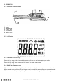
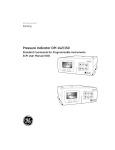
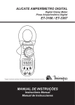
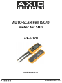
AUTO-SCAN Pen R/C/D
Meter for SMD
AX-507B
USER’S MANUAL
1. GENERAL INSTRUCTIONS
This auto scan pen R/C/D meter fir SMD could fast precise measure small chip components.
To get the best service from this meter, please read this user’s manual carefully and observe the
detailed safety precautions strictly.
1.1. Precautions safety measures
• When using this meter the user must observe all normal safety rules concerning
1.1.1. During use
• Use the meter before must warm-up 30 seconds
• If the meter is used near noise generating equipment, be aware that display may become unstable
or indicate large errors.
• Do not use the meter if it looks damaged.
• Use the meter only as specified in this manual; otherwise the protection provided by the meter
may be impaired.
• Do not operate the meter around explosive gas, vapor, or dust.
• To avoid damages to the instrument, do not exceed the maximum limits of the input values
• Caution: Avoid working with voltages above 50VDC or 36VAC rms. Such voltages pose a shock
hazard and damage the meter
• When using this meter, keep your fingers away from the metal of the meter.
• Before changing functions, disconnect the test clip from the circuit under test.
• Replace the battery when the
false display.
symbol appears. With a low battery, the meter might produce
1.1.2. Symbols
Symbols used in this manual and on thr meter:
Caution: refer to the instruction manual. Incorrect use may result in damage to the device
or its components.
Conforms to IEC1010
1.1.3. Instructions
• Before operating the meter, always disconnect from all sources of electric current and make sure
you are not charged with static electricity, which may destroy internal components.
• Any adjustment, maintenance ot repair work carried out on the meter while it is live should be
carried out only by appropriately qualified personnel, after having taken into account the
instructions in this present manual.
• If any faults or abnormalities are observed, take the instrument out of service and ensure that it
can not be used until it has been checked out.
• If the meter is not going to be used for a long time, take out the battery and do not store the
meter in high temperature or high humidity environment.
• Never use the meter unless the back cover and battery cover are in place and fastened fully.
2
2. DESCRIPTION
2.1. Instrument Familiarization
1. Cathode
2. Anode
3. „RANGE” key
4. „FUNC” KEY
5. LCD DISPLAY
6. Battery cover
2.2. LCD Display
2.3. FUNC. Key-Function key
Press this key longer than 1 second, the meter will turn on and enter auto scan mode.
Press this key less than 1 second could select the target measurement function.
Press the key longer than 2 seconds, the meter will enter sleep mode.
2.4. RANGE key-Changes range
When automatic mode pressing this key less than 1 second, the meter will enter manual mode.
When manual mode pressing this key longer than 1 second the meter will enter automatic mode.
While in manual mode, pressing thi key less then 1 second to changes the full-scale range.
3
2.5. Terminals
• + Terminal receiving the anode
• - Terminal receiving the cathode
Only for measuring the diode and the polar capacitance.
3. TECHNICAL SPECIFICATIONS
3.1. General specifications
• Environment conditions
Pollution degree: 2
Altitiude < 2000m
Operating temperature: 0 ~40°C, (<80%°C or >28°C)
Storage temperature: -10~60°C, (<70%RH, battery removed)
• Temperature Coefficient: 0,1x(specified accuracy)/VC(<18°C or >28°C)
• MAX. Voltage between terminals and earth ground: 50V DC or 36V AC rms
• Sample Rate: 3 times/sec for digital data
• Display: 2 2/3 digits LCD display with max. reading 2999
5 5/6 digits LCD display with max . reading 5999
• Over Range indication: LCD will display “OL”
• Low battery indication: The „
” is displayed when the battery is under the proper operation
range.
• Auto power off: If there key been operated for 10 minutes, the meter will auto power off to save
battery energy.
• Power source: 3.0 V battery.
• Dimension: 181 (L)x35(W)x20(H)mm
• Weight: 65g. Approx.(battery included)
3.2. Measurement specifications
• Accuracy: ±(% of Reading + number of digits) at 18°C to 28° ( 64°F to 82°F) with relative humidity
to 80%
Caution when working with voltages above 50 V DC or 36V AC rms.
3.2.1. Resistance
Range
Resolution
Accuracy
300Ω/600Ω
0.1Ω
±(1.2% of rdg + 2 digits)
3kΩ/6kΩ
1Ω
30kΩ/60kΩ
10Ω
300kΩ/600kΩ
100Ω
3MΩ/6MΩ
1kΩ
30MΩ/60MΩ
10kΩ
±(2.0% of rdg + 5 digits)
4
3.2.2. Capacitance
Range
Resolution
Accuracy
3nF/6nF
1pF
±(5.0% of rdg + 5 digits)
30nF/60nF
10pF
±(3.0% of rdg + 3 digits)
300nF/600nF
100pF
3µF/6µF
1nF
30µF/60µF
10nF
300µF/600µF
100nF
3mF/6mF
1µF
30mF/60mF
10µF
±(5.0% of rdg + 3 digits)
unspecified
Keep two pins of the capacitance in short before maeasuring
3.2.3. Diode Test
Range
Desription
Test Condition
Display read approx. Forward
voltage of diode
Forward DC Current: approx
1mA. Reversed DC Voltage:
approx. 2.8V
2V
3.2.4. Continuity check
The buzzer generates 2 KHZ beep whenever the reading is less than 30 Ω.
4. OPERATING INSTRUCTION
4.1. Auto scan measurement mode
• Pressing this key longer than 1 second the metter will turn on and enter auto mode, now you can
measurement: ohm, diode, capatitance, continuity check.
Note:
• The range when auto scan mod:
Ohm: 300.0 Ω ~3.000M Ω/600.0 Ω~6.000M Ω
Cap: 3nF~300µF/6nF~600µF
5
4.2. Resistance measurement
To avoid elecrical Shock or damages to the meter under test, disconnect circuit power
and discharge all high-voltage capacitors before measuring resistance
• Press FUNC. Key and select the function at
mode.
• Connect the test clip to the object being measured and the measured value will show on the
display.
Note:
• When this mode the RANGE key is available.
• When the input is not connected, i.e. at open circuit, the figure “OL” will be displayed for the
overrange condition.
4.3. Capacitance measurement
To avoid electrical Srock or damages to the meter dunder test, disconnect circuit
Power and discharge all high-voltage capacitors before measuring capacitance. Keep two pins
of the capacitance in short before measuring
• Press FUNC. Key and select the function at
mode.
• Connect the test clip to the capacitor being measured and read the displayed value.
Note:
• When this mode the RANGE key is available
• Discharge the capacitor before measuring
4.4. Diode measurement
To avoid elecrical Srock or damages to the meter dunder test, disconnect circuit Power
and discharge all high-voltage capacitors before testing diodes.
• Press FUNC. Key and select the function at
mode.
• Connect the + pin to the anode, the –pin to the cathode of the diode under testing.
• The meter will show the approx. forward voitage of the diode. If the lead connection is reversed,
only figure “OL” displayed.
6
4.5. Continuity check
• Press FUNC. Key and select the function at
mode.
• Connect the test clip to the resistance. If continity exists (i.e., resistance less than 30 Ω) built – in
buzzer will sound.
5. AUTO POWER OFF(APO)
• To extend the battery life, Auto Power Off function is provided. If no key operations of range
changing happen about 10 minutes, the meter will be turned off automatically.
• When APO happens the state of the meter is saved.
6. MAINTENANCE
6.1. General Maintenance
Periodically wipe the case with a damp cloth mild detergent. Do not use abrasives or solvents.
6.2. Battery replacement
Before replacing the battery disconnect test leads from any circuit under test, turn the
meter off and remove test Leeds from the input terminals.
Use the following procedure:
When the battery voltage drop below proper operation range the
LCD display and the battery need to be replaced.
symbol will appear on the
• Press the battery cover and towards arrowhead direction to open the battery cover.
• Replace the battery with two new 1,5 V batteries (AG 13).
• Replace the battery cover.
7