1
MiS20
the robotic soccer simulator
- Bachelor thesis -
Names:
Date:
Version:
Hans Dollen
Wim Fikkert
June, 13th 2003
1.0
Bachelor thesis – MiS20, the robotic soccer simulator
Hans Dollen
Wim Fikkert
Title:
Version:
MiS20, the robotic soccer simulator
1.0
Authors:
Hans Dollen
Wim Fikkert
Company name:
Department:
University Twente
TKI
Company tutor:
Dr. M. Poel
Saxion tutors:
Ir. J. Meuleman
R.F. Lever
Date:
Location:
June, 13th 2003
Enschede, The Netherlands
(c) 2003, Hans Dollen & Wim Fikkert,
University Twente,
Saxion Hogeschool Enschede,
All rights reserved Saxion Hogeschool Enschede, The Netherlands,
Hogere Informatica education
2
Bachelor thesis – MiS20, the robotic soccer simulator
Hans Dollen
Wim Fikkert
Summary
Robot soccer is an international research effort the goal of which is to explore and apply new and
promising techniques in the field of robotics. The University of Twente is trying to set up its own AI
controlled team (Mi20, or Mission Impossible Twente) in the FIRA MiroSot middle league. This team needs
to be trained and tested in a simulator program. The simulator currently in use does not meet all
requirements set by the Mi20 team. The creation of a new simulator (MiS20, or Mission Impossible
Simulator) is required. Our project goal therefore states:
Create a new realistic simulator for a five against five robot soccer match played according to the
FIRA MiroSot middle league game rules. The robots and the ball must simulate their real
counterparts in an approximately correct way.
This project goal raises a research question which needs to be answered in this project:
When does the level of simulation of the robots and the ball reach the required level of an
approximately correct simulation; which physical aspects need to be taken into account?
The MiS20 was designed using three software design methods; NIAM, OVID and UML. These methods
complement each other in a way that leads to a design which contains all aspects of the simulator
program. The MiS20 was implemented in Java, using CVS and a source code template and was fully
documented using Sun's javadoc.
Various available robot soccer research documents were used to create a dynamic and kinematic
representation of the robots and the ball which simulates their real counterparts in an approximately
correct way.
Samenvatting
Robot voetbal is een internationaal onderzoeksproject waarvan het doel is om nieuwe en veel belovende
technieken op het gebied van robotica toe te passen en te onderzoeken. De Universiteit Twente is bezig
om een door Kunstmatige Intelligentie (KI) aangestuurd team (Mi20, ookwel Mission Impossible) op te
zetten. Dit team moet worden getraind en getest m.b.v. een simulator. De simulator welke momenteel in
gebruik is voldoet niet aan alle eisen welke het Mi20 team stelt. Hierdoor is het noodzakelijk om een
nieuwe simulator te ontwikkelen, genaamd MiS20 (hetgeen staat voor Mission Impossible Simulator).
Deze ontwikkeling staat beschreven in dit document. Onze project doelstelling luidt dan ook:
Maak een nieuwe simulator waarin een vijf tegen vijf robot voetbal wedstrijd, conform de FIRA
MiroSot middle league spelregels, gespeeld kan worden. De robots en de bal moeten hun echte
equivalente tegenhanger zo goed mogelijk simuleren.
Hierbij doet zich een onderzoeksvraag aan welke in dit project beantwoord moet worden:
Welke mate van simulatie precisie is voldoende om aan het geëiste niveau van simulatie te kunnen
voldoen; welke natuurkundige aspecten moeten hierbij betrokken worden?
De simulator is ontworpen door gebruik te maken van drie software ontwerp methoden; NIAM, OVID en
UML. Deze methoden vullen elkaar in dusdanige mate aan, dat het resultaat een ontwerp is waarbij alle
aspecten van de simulator aan bod komen. Hierna is de simulator geïmplementeerd in Java, m.b.v. CVS
en een source code template. Tijdens dit proces is de source code uitgebreid gedocumenteerd middels
Sun's javadoc.
Tenslotte is er een dynamisch en kinematisch model gemaakt van de robots en de bal door gebruik te
maken van diverse beschikbare robot voetbal onderzoeksdocumenten.
3
Bachelor thesis – MiS20, the robotic soccer simulator
Hans Dollen
Wim Fikkert
Preface
This document marks the final phase of our education at the Saxion Hogeschool Enschede. We have tried
to describe in detail our activities these last 20 weeks regarding our bachelor thesis project, short
summaries regarding studied literature and theories and the choices we have had to make.
When we started this project we actually had no knowledge of robotic soccer other than a short
documentary on the television. We started off by doing a lot of reading, in the mean time getting more and
more on the subject. Eventually we have had to put a lot of hard work on documenting our entire venture
because that was the thing often overlooked whilst programming and researching.
We would like to thank Jan Meuleman and Mannes Poel for supporting us on various fronts during our
project, our families for having to put with our “interesting” robot soccer stories and the remaining UT staff
whom we “bothered” the last few months, Hendri Hondorp in particular. We would also like to thank our
review team; André van der Zijden, Michiel Korthuis and Lynn Packwood. And last but not least, we would
like to thank the Mi20 team, Werner, Niek and Remco for us having a great time with them on the Mi20
project.
This document is accompanied by a CD-Rom disc containing all products we created during our project.
The file tree below indicates which items can be found at what location.
4
Bachelor thesis – MiS20, the robotic soccer simulator
Hans Dollen
Wim Fikkert
Table of Contents
1. About.................................................................................................................................................
9
1.1. Context..............................................................................................................................................
9
1.1.1. Mi20 progress.........................................................................................................................................9
1.1.2. Need for a simulator...............................................................................................................................9
1.1.3. Alternative simulator.............................................................................................................................10
1.2. Project goal.....................................................................................................................................11
1.3. Project approach.............................................................................................................................11
1.3.1.
1.3.2.
1.3.3.
1.3.4.
1.3.5.
Schedule...............................................................................................................................................
11
Risk management................................................................................................................................11
Iterations...............................................................................................................................................11
Design methods...................................................................................................................................12
Quality management............................................................................................................................12
1.4. Document structure.........................................................................................................................12
2. Requirements.................................................................................................................................13
2.1. System............................................................................................................................................
13
2.1.1.
2.1.2.
2.1.3.
2.1.4.
2.1.5.
Interface................................................................................................................................................
13
Approximate correct simulation............................................................................................................13
FIRA regulations...................................................................................................................................13
Logging.................................................................................................................................................13
Expansion.............................................................................................................................................13
2.2. User.................................................................................................................................................14
2.2.1.
2.2.2.
2.2.3.
2.2.4.
2.2.5.
2.2.6.
2.2.7.
2.2.8.
Object representation...........................................................................................................................14
Options.................................................................................................................................................14
Stop and resume..................................................................................................................................14
Match data............................................................................................................................................14
Manual referee.....................................................................................................................................14
Messaging............................................................................................................................................14
Objects.................................................................................................................................................14
Logging.................................................................................................................................................14
2.3. Implementation...............................................................................................................................15
2.3.1. Language..............................................................................................................................................
15
2.3.2. Error handling.......................................................................................................................................15
2.3.3. Assertions.............................................................................................................................................15
2.4. Optional...........................................................................................................................................15
2.4.1. Multiple camera vantage points............................................................................................................15
2.4.2. Automated referee................................................................................................................................15
3. Analysis and design.......................................................................................................................16
3.1. FIRA simulator................................................................................................................................16
3.2. Mission Impossible Simulator.........................................................................................................16
3.3. Model..............................................................................................................................................
17
3.3.1.
3.3.2.
3.3.3.
3.3.4.
3.3.5.
3.3.6.
3.3.7.
3.3.8.
3.3.9.
A robot soccer match description.........................................................................................................17
Objects.................................................................................................................................................17
Relationships........................................................................................................................................18
Storing data..........................................................................................................................................19
Updating data.......................................................................................................................................19
The soccer field mathematics..............................................................................................................20
Robot wheelspeeds..............................................................................................................................20
Collisions..............................................................................................................................................20
Kinematic models.................................................................................................................................24
3.4. Control.............................................................................................................................................27
3.5. View................................................................................................................................................
29
3.5.1. Panels...................................................................................................................................................30
3.6. Communication interface................................................................................................................31
3.6.1. Mi20......................................................................................................................................................31
3.6.2. Sending and receiving..........................................................................................................................32
3.6.3. Java Native Interface............................................................................................................................32
3.7. Decisions summarized....................................................................................................................33
5
Bachelor thesis – MiS20, the robotic soccer simulator
Hans Dollen
Wim Fikkert
4. Implementation...............................................................................................................................34
4.1. Design changes..............................................................................................................................34
4.1.1.
4.1.2.
4.1.3.
4.1.4.
The referee...........................................................................................................................................34
Settings.................................................................................................................................................34
Popups.................................................................................................................................................34
Messaging............................................................................................................................................35
4.2. Model..............................................................................................................................................
35
4.2.1.
4.2.2.
4.2.3.
4.2.4.
Files......................................................................................................................................................35
Propertychange events........................................................................................................................35
Collisions..............................................................................................................................................36
Kinematic models.................................................................................................................................36
4.3. View................................................................................................................................................
37
4.3.1. GUI components..................................................................................................................................37
4.3.2. Heavyweight components....................................................................................................................39
4.4. Control.............................................................................................................................................39
4.4.1. Action events........................................................................................................................................39
4.4.2. Java3D picking ....................................................................................................................................39
4.5. Communication interface................................................................................................................40
4.6. Performance...................................................................................................................................41
4.6.1.
4.6.2.
4.6.3.
4.6.4.
Profiling.................................................................................................................................................41
Collections............................................................................................................................................42
StringBuffers.........................................................................................................................................42
Object creation.....................................................................................................................................43
4.7. Implementation summarized...........................................................................................................43
5. Testing.............................................................................................................................................45
5.1. Model..............................................................................................................................................
45
5.1.1.Variables................................................................................................................................................
45
5.1.2. Object creation.....................................................................................................................................45
5.1.3. XML parser...........................................................................................................................................45
5.1.4. Collisions..............................................................................................................................................46
5.1.5. Kinematic models.................................................................................................................................46
5.2. View................................................................................................................................................
46
5.3. Control.............................................................................................................................................46
5.3.1. User interactions..................................................................................................................................46
5.3.2. The referee...........................................................................................................................................47
5.4. Communication interface................................................................................................................47
5.4.1. Receiving..............................................................................................................................................47
5.4.2. Sending................................................................................................................................................47
5.5. Tracebility matrix.............................................................................................................................47
5.6. Testing summary............................................................................................................................48
6. Results............................................................................................................................................49
6.1. Documents......................................................................................................................................49
6.2. MiS20..............................................................................................................................................
49
6.2.1. Integration.............................................................................................................................................
49
6.2.2. Approximately correct simulation.........................................................................................................49
6.2.3. OS indepent..........................................................................................................................................
50
7. Conclusions....................................................................................................................................51
7.1 Comparison with the current simulator............................................................................................51
7.2 Dynamic and kinematic models.......................................................................................................51
7.3. Collision detection...........................................................................................................................51
7.4. Collision handling............................................................................................................................51
7.5. Overall conclusion...........................................................................................................................51
6
Bachelor thesis – MiS20, the robotic soccer simulator
Hans Dollen
Wim Fikkert
8. Recommendations.........................................................................................................................52
8.1. Simulation.......................................................................................................................................52
8.1.1. Ball simulation......................................................................................................................................52
8.1.2. Robot simulation...................................................................................................................................52
8.2. Collisions.........................................................................................................................................52
8.2.1. Collision detection................................................................................................................................52
8.2.2. Collision handling.................................................................................................................................52
8.3. JNI interface with the C++ communication.....................................................................................53
8.4. Running on other Operating Systems.............................................................................................53
8.5. Implementing optional requirements...............................................................................................53
8.6. Sliding bar for replaying matches....................................................................................................53
8.7. More time........................................................................................................................................
53
9. Personal reflection.........................................................................................................................54
9.1 Personal reflection of Hans..............................................................................................................54
9.2. Personal reflection of Wim..............................................................................................................54
References..........................................................................................................................................55
Glossary..............................................................................................................................................56
Appendices.........................................................................................................................................57
Appendix A. Project schedule................................................................................................................58
Appendix B. User manual......................................................................................................................60
Warnings........................................................................................................................................................60
Contents.........................................................................................................................................................60
Preface...........................................................................................................................................................60
Program controls............................................................................................................................................61
System requirements......................................................................................................................................61
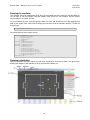
Running the simulator....................................................................................................................................62
Running a simulation......................................................................................................................................62
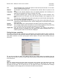
Managing the simulator..................................................................................................................................64
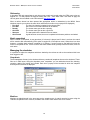
Replaying a logged match..............................................................................................................................65
Credits............................................................................................................................................................65
Contact data...................................................................................................................................................65
Copyrights......................................................................................................................................................65
Appendix C. Developers manual...........................................................................................................66
C.1. Automated referee..................................................................................................................................66
C.2. Various camera vantage points..............................................................................................................66
C.3. MiroSot small and large leagues............................................................................................................67
C.4. Match settings.........................................................................................................................................67
C.5. Improved collisions.................................................................................................................................68
C.6. Kinematic models...................................................................................................................................68
Appendix D. UML diagrams...................................................................................................................70
D.1. Model......................................................................................................................................................70
7
Bachelor thesis – MiS20, the robotic soccer simulator
Hans Dollen
Wim Fikkert
Illustration Index
1.1. The overall system system used by the Mi20 robot soccer team
3.1. IGD – normalised objects
3.2. IGD – object relationships
3.3. The used axes and heading in the MiS20 soccer field
3.4. 2D collision detection suffices
3.5. AABB collision detection
3.6. Bounding sphere collision detection.
3.7. MiS20 robot versus robot collision
3.8. MiS20 robot versus ball collision
3.9. A new coordinate system
3.10. Ball friction model
3.11. Two different robot wheel speeds result in a new heading
3.12. User use cases
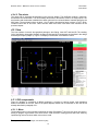
3.13. The MiS20 simulator GUI design
3.14. The GUI panels
3.15. The Mi20 communication interface
4.1. Applied MVC model
4.2. A MiS20 screenshot
4.3. Java3D Scene Graph used in the Mi20 simulator
D.1. The model UML diagram
8
10
18
18
20
20
22
22
22
22
23
24
26
27
29
30
31
34
37
38
70
Bachelor thesis – MiS20, the robotic soccer simulator
Hans Dollen
Wim Fikkert
1. About
1.1. Context
Robot soccer is an international research effort the goal of which is to explore and apply new and
promising techniques in the field of robotics. Example technologies are multi-agent systems, sensor fusion,
machine learning and planning. Since 1997 a robot soccer competition has taken place each year in which
a lot of teams in different leagues (simulation, small-size, middle-size, four-legged, etc.) play against each
other. After such a competition, the participating teams release their research which can be studied and
used by other (new) teams. This process results in better robot soccer results year after year.
The UT (University of Twente) is new to the field and is trying to set up a team to play in the middle league
of the FIRA1 MiroSot competition. This robot soccer team is called Mi202 (Mission Impossible Twente). In
this competition five small robots form a team. By participating in this league, the UT hopes to gain a
valuable insight into AI (Artificial Intelligence), multi-agent systems, etc. which is needed to let a team of
robots play a match of soccer. The attained knowledge can then be used by and used in other projects.
For information about FIRA game rules which apply in a match of robot soccer, see the FIRA regulations3.
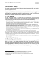
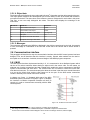
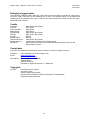
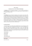
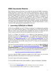
1.1.1. Mi20 progress
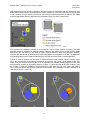
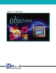
The Mi20 team has currently almost finished constructing their robot soccer team. Figure 1.1 on the
following page describes the distributed system used by the Mi20 team to accomplish a working robot
soccer team. The red highlighted system (number one) in figure 1.1 contains a global vision system which
determines all individual robot and ball positions and headings4, called vectors5, from the soccer field it
observes. These vectors are sent (in a so called snapshot6) to and analyzed by system number two. This
system determines the strategies and actions to be taken by individual Mi20 robots. Next, these robot
actions are sent to and translated by system three which calculates robot wheelspeeds which will
maneuver the Mi20 robots on the soccer field. These wheelspeeds are sent to system one which, in turn,
sends those wheelspeeds to the Mi20 robots on the soccer field via a radio frequency link.
In the meantime, the opponent team is also maneuvering its robots to new positions on the soccer field
using a (similar) control system of their own. These new opponent robot vectors, those of the Mi20 robots
and the new ball vector are then again retrieved by the global vision system after which the process starts
anew. This entire cycle will be completed 30 times per second7.
1.1.2. Need for a simulator
Systems two and three in figure 1.1 use a sophisticated AI (Artificial Intelligence) control system to
determine robot actions and to control the Mi20 robots respectively. To test these systems and to train the
AI components, a simulator, currently provided by the FIRA from the FIRA SimuroSot league8, is being
used. Such a simulator will replace system one and the soccer field containing all robots and the ball
entirely (see also the red highlighted system in figure 1.1). In order to accomplish that, the simulator will
have to comply to the communication interface which is described by the Mi20 team. This interface is
described in detail in paragraph 3.6. Suffice to say here, snapshots have to be sent and wheelspeeds have
to be received by a simulator.
1
. FIRA, or Federation of International Robot-soccer Association, see reference [W2].
. See the Mi20 homepage; reference [W1].
3
. FIRA MiroSot Middle League rules can be found in reference [B1].
4
. Headings indicate the orientation of the robot or ball according to the x axis of the soccer field.
5
. Mathematical vectors used in the MiS20 contain x and y positions, a heading and timestamp.
6
. A snapshot contains vectors for the ball and the robots of both teams.
7
. The camera used in the global vision system has a framerate of 30 frames per second.
8
. The FIRA SimuroSot league is the simulation league of the FIRA. Only AI is used here.
2
9
Bachelor thesis – MiS20, the robotic soccer simulator
Hans Dollen
Wim Fikkert
Figure 1.1. The overall system system used by the Mi20 robot soccer team
The FIRA simulator, which is currently used, does not meet all requirements set by the Mi20 team9. It also
cannot be changed to meet those requirements since it is not open source. Therefore, a different simulator
has to be found or created for use in the Mi20 robot soccer project.
1.1.3. Alternative simulator
The FIRA simulator is not the only robot soccer simulator available for simulating robot soccer matches.
Besides the FIRA robot soccer initiative there is another initiative, called RoboCup. RoboCup also has a
simulation league for which a simulator is used. This simulator however, is set at two teams of 11 robots
each playing a match of robot soccer. It is open source so it is possible to adjust it to meet the
requirements stated by the Mi20 team. However, the RoboCup initiative differs to such an extent from the
FIRA initiative that, doing so, would result in almost completely rebuilding the RoboCup simulator.
Besides these two robot soccer simulator programs, there are no other publicly available robot soccer
simulators. Also, the creators of the FIRA simulator will not release their source code when asked. The
only solution left is to create a new robot soccer simulator. The requirements for this new simulater are
stated in the requirements chapter9.
9
. The Mi20 requirements are described in chapter 2.
10
Bachelor thesis – MiS20, the robotic soccer simulator
Hans Dollen
Wim Fikkert
1.2. Project goal
A new simulator for use in the Mi20 robot soccer project will have to simulate the objects (robots and ball)
in an approximately correct way. Otherwise, the Mi20 AI control system (systems two and three in figure
1.1) will learn to apply certain strategies which will not work when controlling the real robots instead of the
simulator. We have named this new simulator “MiS20”, which stands for “Mission Impossible Simulator”.
So, summarizing, the goal of our project is:
Create a new realistic simulator for a five against five robot soccer match played according to the
FIRA MiroSot middle league game rules. The robots and the ball must simulate their real
counterparts in an approximately correct way.
This project goal leads to a research question which we will need to answer in this project:
When does the level of simulation of the robots and the ball reach the required level of an
approximately correct simulation; which physical aspects need to be taken into account?
1.3. Project approach
This paragraph describes the approach we used to accomplish the project goal. First we will describe the
schedule we used for this project. This is followed by our utilization of risk management and how we used
an iterative project approach. In conclusion, we will state our use of quality management.
1.3.1. Schedule
At the beginning of the MiS20 project we created a schedule which contained all relevant deadlines. This
schedule can be found in appendix A. We had little difficulty reaching those deadlines in time. However,
some documents, such as our design document, were altered after the first release on the deadline date.
1.3.2. Risk management
We used basic risk management to overcome unexpected setbacks. An extra week was planned in case
of illness. CVS10 was used to ensure that as little loss of data as possible. We did not apply extensive risk
management strategies such as determining risk weights for each set deadline because it would result in
too much overhead and because we have too little experience which is a risk in itself. Further, we worked
using iterations. This iterative project approach gradually expanded the MiS20.
1.3.3. Iterations
Our first iteration consisted of creating a simple prototype program. This only implemented the basic data
model and a relatively simple GUI11. Information from the data model was only displayed to the user.
The second iteration expanded on the first one by adding the communication with the Mi20 control system.
Also, data logging to XML files was created12.
The third iteration expanded even further on the previous two. An XML parser was written to retrieve data
which has been logged to file. Also, the GUI was updated with a 3D view of the soccer field and with user
controls to control a match. We also researched collision detection and collision handling techniques.
The fourth, and final, iteration included mainly performance boosts to increase the MiS20 program's speed.
The collision detection and collision handling techniques found in the previous iteration were implemented
in the simulator. Also, we began researching and implementing kinematic and dynamic object models
which can be used in the Mission Impossible Simulator. After this iteration we were able to simulate an
entire robot soccer match.
10
. See reference [W9].
. GUI, or Graphical User Interface.
12
. MiS20 program components are derived in the chapters two through five.
11
11
Bachelor thesis – MiS20, the robotic soccer simulator
Hans Dollen
Wim Fikkert
1.3.4. Design methods
In this iterative process three design methods have been used to create a project design; NIAM, OVID and
UML13. NIAM models the static data whereas OVID described a user interface seen from the users point of
view. UML then models the results from NIAM and OVID. The resulting UML design was implemented
using Java, Java3D and JNI. The created source code complies to a standard as seen in our
implementation document14. These design methods ensure that MiS20 may be easily expanded.
1.3.5. Quality management
To ensure the quality of our software and documentation we have created templates to which all source
code and documents will be created. The source code template can be found in our implementation
document14. We also utilized reviewing of source code and documentation. Source code was reviewed by
ourselves. The documents we created were reviewed by UT personnel, our Saxion tutor and peers from
the Saxion College.
1.4. Document structure
Chapter 2
Chapter 3
Chapter 4
Chapter 5
Chapter 6
Chapter 7
Chapter 8
Chapter 9
13
14
states and explains the requirements regarding the MiS20.
describes the analysis made and design created for the MiS20 robot soccer simulator, all
steps of the analysis and design are explained.
states the implementation phase of the simulator. Also, implementation difficulties and
their solutions are explained.
displays the test methods used for testing the simulator. The test results are also
described in this chapter.
contains all project results.
states the project conclusions.
describes the recommendations which can be made regarding this project.
contains our the personal reflection on the project.
. See glossary and references [B4], [B6] and [B9] for more information.
. See reference [B7].
12
Bachelor thesis – MiS20, the robotic soccer simulator
Hans Dollen
Wim Fikkert
2. Requirements
This chapter will state and explain all requirements the MiS20 must comply to. They have been separated
into different groups; system, user, implementation and optional. The requirements in this chapter have
been derived by discussing with the future users (the Mi20 team) and by examining the existing FIRA
simulator.
2.1. System
This paragraph states the general system requirements. The MiS20 has to be integrated into the existing
Mi20 system, it will have to simulate an entire match in an approximately correct way and it needs to be
able to store logged data to and read logged data from disk.
Also, the MiS20 must replace system one in figure 1.1. In order to perform that task, the simulator will have
to generate snapshots at an interval of at least 33 milliseconds. This interval can be derived from the
global vision system used by the Mi20 team. This system uses a camera which has a framerate of 30
frames per second. This results in 33 milliseconds per frame.
2.1.1. Interface
MiS20 will be a part of the distributed Mi20 system. As seen in figure 1.1, the MiS20 will replace the system
containing the global vision component and the actual playing field (number one) entirely. Since that
system communicates with the remaining distributed Mi20 systems (numbers two and three in figure 1.1)
the simulator must use that set interface. This interface with the Mi20 distributed system is described in our
design document1.
2.1.2. Approximate correct simulation
As seen in paragraph 1.2, the MiS20 will have to simulate the robots and the ball in an approximately
correct way. Therefore, a dynamic and kinematic model for the robots and ball has to be created. This
model uses various physical aspects such as friction and acceleration as well as collision results; what will
happen when a robot collides with the ball, another robot or a wall? Such an approximately correct way of
representing a robot or ball is required because the AI system would learn to apply different strategies as it
should do when using the real robots.
2.1.3. FIRA regulations
Not only the robots and the ball need to be simulated, but also the match itself. To simulate a match
correctly it must be possible to simulate the application of the rules the FIRA regulations state2. In a real
match, a human referee applies those rules. Hence, it must be possible to referee a match.
2.1.4. Logging
All data generated during a robot soccer match must be logged to disk. This match data can be read from
file later on to review the match. Also, it must be possible to read from, write to, edit and delete from disk
certain fixed locations (called snapshots) for the robots and the ball.
It is necessary to log matches and snapshots for reuse. A match can be (re)played in the simulator to
evaluate where things went wrong. Snapshots can be used by the referee to position the robots and ball in
a goal kick situation for example. Also, snapshots can be used to test certain decisions from the AI control
system as described in figure 1.1.
2.1.5. Expansion
The Mission Impossible Simulator must be designed and implemented in such a way that it can easily be
expanded upon. This is necessary because it will most likely be expanded in various ways.
1
2
. See reference [B3].
. See reference [B1].
13
Bachelor thesis – MiS20, the robotic soccer simulator
Hans Dollen
Wim Fikkert
2.2. User
This chapter describes the requirements to which the (GUI of the) simulator must comply to regarding the
user's interaction with the system and vice versa.
2.2.1. Object representation
The soccer field must be displayed in 3D. The field, robots and the ball must have correct colors, size and
aspect ratio between objects. Also the data for each of the objects in the match must be displayed in an
unambiguous way. The reason for this 3D representation is to enable simulation of robot vision and other,
not yet applied, technologies.
2.2.2. Options
A user must be able to set various options in the simulator which will enable him or her to test the Mi20 AI
control system. These options include: collision detection on/off, application of FIRA rules on/off, ability to
switch between various control modes per team.
The latter requires some explanation; it must be possible to change the way a team is controlled (where it
receives its wheelspeeds from). This will enable the possibility of letting a team play against itself and
against human controlled robots (via joysticks).
2.2.3. Stop and resume
A user must be able to stop and resume the simulator at any time he or she chooses. Whilst the simulator
is stopped, it can be manipulated by the user: robots can be repositioned, another snapshot can be loaded,
etc.
2.2.4. Match data
A match consists of two teams and a ball. These teams consist, in turn, of a set of robots. The match
objects (the robots and the ball) are represented to the user as described in paragraph 2.2.2. A match also
has an elapsed time and a score per team. Both of these values should be displayed at all times. These
values must be sent every five seconds to the Mi20 system.
2.2.5. Manual referee
As described in paragraph 2.1.3, the MiS20 must have the ability to apply FIRA regulations to a match.
Since an automated referee would take a lot of time and effort to construct, the most reachable solution for
the requirement as stated in paragraph 2.1.3 is to let the user referee a match. A FIRA referee has to be
able to call the following situations according to the FIRA game rules: free ball, free kick, goal kick, penalty
kick, kick off and goal scored. Also, he or she must be able to pause a match at any given moment.
2.2.6. Messaging
The user must be provided with messages stating which action is required from the user. These messages
can be divided into two different groups: not important (displaying a line to the user which contains the
current system state) and important (user will be confronted with this message using a pop up window for
example).
2.2.7. Objects
The objects (the ball and all robots) in a match must be manipulatable. A user must be able to reposition
an object in the soccer field. Also, a user must be able to apply a new heading to an object.
2.2.8. Logging
As described in paragraph 2.1.4, match data and snapshots must be logged to disk. A user must be able
to administrate those files using the simulator; file deleting, storing, reading and editing (only for
snapshots).
14
Bachelor thesis – MiS20, the robotic soccer simulator
Hans Dollen
Wim Fikkert
2.3. Implementation
This chapter will describe the implementation requirements. We must comply with these requirements
while programming.
2.3.1. Language
The simulator must be implemented using Java and Java3D. The reason for this is that it can easily be
expanded upon easily by UT students among others.
2.3.2. Error handling
MiS20 should be programmed in such a way that when errors occur these are handled correctly: the
simulator should not crash but display a message to the user and display a detailed error message to the
command line indicating the source and reason of the error.
2.3.3. Assertions
Assertions are to be used to ensure object data has been set or altered correctly. These assertions should
be removed in the final version of the Mission Impossible Simulator since they cause an unnecessary
overhead.
2.4. Optional
This chapter describes the optional requirements which will only be implemented in the simulator if there is
any time left. However they should be used when designing the new simulator system to be able to expand
upon the simulator we will create. This should ease expansion of MiS20 by other students.
2.4.1. Multiple camera vantage points
The user must be able to switch between different camera vantage points in the 3D representation of the
robot soccer field. A few examples of these vantage points are:
• Top-down (default, views the entire field to top-down as if it were the real global vision system);
• Free camera (ability to move the camera freely through the 3D soccer field representation);
• Object pursuit (the camera follows an object around the field).
2.4.2. Automated referee
At first the simulator will be equipped with a manual referee option. This requires user interaction (a user
should be applying the FIRA rules). The logical course of action for our simulator is to have an automated
referee which can call situations automatically. This can be used to train the Mi20 AI control system even
when no user is present (during weekends for example). Further, when this option has been implemented
an option must be added to turn it on and off.
15
Bachelor thesis – MiS20, the robotic soccer simulator
Hans Dollen
Wim Fikkert
3. Analysis and design
This chapter describes the analysis of the MiS20 as well as the design created for it. The standard Model
View Control design principle was used to design the Mission Impossible Simulator. This chapter is
structured in much the same way.
First, the “old” FIRA simulator is described with its shortcomings. Second, the model is analysed and
designed using NIAM1. Third, the user interactions (control) with the MiS20 are designed using UML2 use
cases. Fourth, the view is designed using the FIRA simulator GUI as a base and by using OVID3. Fifth, the
communication with the existing Mi20 components is designed using UML. Finally, all components are
integrated in one overall UML design which can be implemented by a programmer.
3.1. FIRA simulator
The FIRA simulator was created by a professor and a few students of the School of Information
Technology of the Griffith University in Australia4. This simulator has a number of flaws which make it not
entirely suitable for use in the Mi20 robot soccer project. A list of these flaws or shortcomings:
• Manual action is required to exit replay mode, as well as in various other menu's. This requires constant
human user interaction.
• The simulation, provided by this simulator, is not precise enough. Objects are not modelled using a
kinematic and dynamic model which approximates the real world as best as possible. Therefore, the AI
control system will not learn well enough by using this simulator.
• The FIRA simulator is not open source, which means that it cannot be changed, expanded upon etc.
• Simulation settings and generated match data cannot be saved to disk directly. This means that there
can be no reuse of generated match and snapshot data.
• No object positions can be loaded (from file) into the simulator to test or train a specific setting (for
example a penalty kick). This has to be done manually for each try.
• Robot representations are not unambiguous; robots are to be identified using a colored patch. This may
very well result in unnecessary user errors.
• No FIRA regulations5 can be applied since no referee option (manual or automated) is present.
The remainder of this chapter will use the shortcomings of the FIRA simulator as stated above and the
requirements as stated in chapter two to design the Mi20 simulator. The FIRA simulator also incorporates
a number of properties which have proven very useful and will be required in the new simulator. These are:
• A 3D view of the soccer field.
• Use of various robot control methods, for example the possiblity to control both teams using the same
(AI) control system.
• Extensive help messages to the user.
3.2. Mission Impossible Simulator
MiS20, the robot soccer simulator we will construct in our project, will resolve the shortcomings of the FIRA
simulator as well as using the useful aspects of it. Since we will use the MVC design principle to construct
MiS20, it will consist of three separate components; model, control and view. MiS20 will have to
communicate with the existing Mi20 control system via a set communication interface. The four resulting
components of MiS20 will be explained in the remainder of this chapter. The model component will include
data storage and updating vector data. The control component will describe which interactions are possible
with the MiS20. The view component will include the design of the graphical user interface. Finally, the
communication interface will describe the exact interface with the Mi20 control system.
1
. NIAM, or Natural language Information Analysis Method, see reference and glossary [B5].
. UML, or Unified Modelling Language, see reference [B6] and glossary.
3
. OVID, or Objects, Views, and Interaction Design, see reference [B9] and glossary.
4
. From the help file of the FIRA robot soccer simulator, for more information see reference [W2].
5
. See reference [B1].
2
16
Bachelor thesis – MiS20, the robotic soccer simulator
Hans Dollen
Wim Fikkert
3.3. Model
NIAM constructs a data structure which can be used to create a database, UML objects etc. First, a world
description is made which describes all aspects of the robotic soccer “world” in detail. Second, objects are
distilled from this description. Third, the way objects in the robotic soccer world (found in the previous step)
interact with one another is described. All restrictions on these interactions are taken into account. Finally,
the resulting data structure is displayed in a so called Information Grammar Diagram or IGD. This IGD
states all steps as described above.
This paragraph explains the steps taken to create a data structure for the MiS20. Our entire NIAM analysis
is described in all detail in our design document6. We will not describe the entire NIAM analysis here.
3.3.1. A robot soccer match description
A robot soccer match is played by two teams, consisting of five robots each. Each team has a color, either
yellow or blue, which is determined prior to each match by a match referee. The goal is the same for both
teams: score as many goals as possible to win the match. The match lasts ten minutes, five per half. After
each match half the teams switch ends field halfs.
The time will be halted whenever the referee pauses the match. This can be done for various reasons, a
foul play has occurred, a goal has been scored etc. If there is a draw after the ten minutes of official play
time, the game will be continued for three additional minutes in which a sudden death (or golden goal)
scheme is applied. If there still is a tie after sudden death, penalty kicks will be taken; three per team, until
there is a winner7.
Each team is controlled by three human players (coaches). These people cannot and may not interfere
with their team during play. Two substitutions are allowed during game time, however at half time unlimited
substitutions may be made. Further, it is the referee's task to call fouls in the game, a few of which are:
deliberate colliding with an opponent robot, pushing the opponent goal keeper in its goal, attacking with
more than one robot and defending with more than one robot7.
A match contains a set of objects. These objects have a vector8 in the soccer field and are identified by a
number. Also, each of these objects contains a list of previous positions. These objects can be divided into
two groups; robots and balls. Since there is only one ball, the other objects in a match are solely robots.
Robots are part of one of the two teams playing in a match. Such a team is identified by a number. Each
team contains five robots. The team color (yellow or blue) identifies these robots. Each robot is, not
necessarily, identified by an individual color and id number. Further, each robot has two wheels (left and
right) which each have an individual speed and acceleration, the latter being equal in most cases.
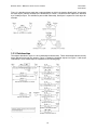
3.3.2. Objects
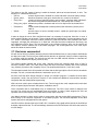
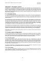
The objects which NIAM distills from the world description given in paragraph 3.3.1 can be represented in
an IGD9. Most of the time, such objects are identified by a name or a number (like the robot for instance).
These are called "normalised" objects in NIAM. Normalised objects can also be identified by other objects,
indicating a parent-child relationship. The objects found from paragraph 3.3.1 are fully stated in our design
document6. Figure 3.1 on the following page gives the most important components. These represent a
match having two teams (consisting of five robots each) and a ball.
6
. See reference [B3] for the MiS20 design document.
. The FIRA regulations are stated in reference [B1].
8
. Mathematical vectors contain a x and y position, a heading and a timestamp. Not to be confused with a Java
java.util.Vector class
9
. IGD; Information Grammar Diagram, see reference [B5] and glossary.
7
17
Bachelor thesis – MiS20, the robotic soccer simulator
Hans Dollen
Wim Fikkert
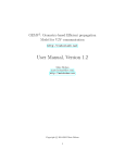
Figure 3.1 describes that a match has a name and date on which it is played to identify itself. A team and
an match object (called a SimObject) are identified by a number. The ball and robot objects are identified
by a SimObject object. This indicates a parent-child relationship; SimObject is a parent of a ball object for
example.
Figure 3.1. IGD – normalised objects
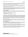
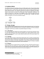
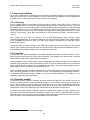
3.3.3. Relationships
The objects described in figure 3.1 have relationships between them. Those relationships indicate the way
these objects interact with one another. Figure 3.2 states the simplified objects from figure 3.1 with those
relationships. These relationships are explained on the following page.
Figure 3.2. IGD – object relationships
18
Bachelor thesis – MiS20, the robotic soccer simulator
Hans Dollen
Wim Fikkert
The match object contains two different teams which will play against each other. It has a playtime and a
currenttime, the first indicating the entire time a match should last and the latter indicating the current time
of the match. Finally, a match has a ball the teams of robots will play with.
The teams in a match each contain five different robots. Each team has a unique color (either blue or
yellow) which will identify it. Also, a team keeps track of its own set of goals it has scored as well as the
half it is playing from currently (either left or right).
The robots in a team, as well as the ball, are child objects of the SimObject object. Such a SimObject
keeps track of where it has been during the match via a list of vectors. The last vector in this list being the
current vector position of that SimObject. A SimObject has a weight in grams which is to be used in the
kinematic and dynamic models of the robots and the ball.
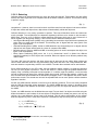
3.3.4. Storing data
The requirement in paragraph 2.1.4 states that generated match data and snapshots, indicating FIRA
situations such as free ball for example, are to be logged to file. This data can be saved using various file
layouts:
• XML, the new standard for communication and saving data;
• A new, selfmade, file layout with tags etc;
• A database;
• Java Property files, a method to save data to file using Java.
These methods all require some kind of file parser/writer. The latter, Java Property files, already
incorporates such a file parser/writer which would result in less work. However, since XML is being used
more and more frequently and the possibility for the Mi20 project to reuse the XML generated by the
simulator the XML option would be the better choice. There are ready made XML parsers available on the
internet as well as at the UT. The use of a self made file layout will result in too much work since a file
parser will have to be created from scratch. Finally, the use of a database results in too much overhead
which also rules out this option.
Two XML layouts have been designed which incorporate all information regarding snapshots and matches
respectively. Only the basic information needed in these layouts is being stored. The design document10
describes these layouts in great detail.
3.3.5. Updating data
When a robot soccer match is being simulated the simulator (in our case, MiS20) will receive wheelspeeds
from the Mi20 control system. These wheelspeeds are translated into new vectors for each robot in the
match. The ball also gets a new vector depending on its speed and possible collisions.
Updating these vectors is done 30 times per second11. The latest known wheelspeeds for each robot are
used to update the vectors. These new vectors are then added to the vector history list which we described
in paragraph 3.3.3. The current vector for an object is the last vector in the vectorlist.
Since it would be useless to update the object representation in the MiS20 GUI when no changes have
been made, this will only be done when a new vector has been set for an object (robot or ball). The GUI
will then update its representation of that robot or ball according to that new vector.
10
11
. For the MiS20 design document, see reference [B4].
. Identical to the framerate the camera used by the Mi20 global vision system.
19
Bachelor thesis – MiS20, the robotic soccer simulator
Hans Dollen
Wim Fikkert
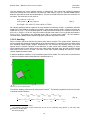
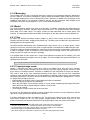
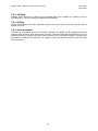
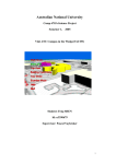
3.3.6. The soccer field mathematics
The soccer field which will be represented in the MiS20 will have two axes which are used for all robots
and the ball. Figure 3.3 represents the axes system which is used in the Mi20 control system. Since we will
need to communicate with that system it is only logical to use those settings ourselves.
Figure 3.3. The used axes and heading in the MiS20 soccer field
3.3.7. Robot wheelspeeds
The robots have two wheels, each of which has a different wheelspeed. These two wheelspeeds enable a
robot to turn and thereby maneuver on the soccer field. The Mi20 control system uses so called PWM or
Pulse Width Modulation12 to represent these wheelspeeds. This wheel PWM value indicates the current
wheelspeed in millimeters per second (mm/s).
3.3.8. Collisions
When the robots maneuver on the soccer field in a match they will undoubtably collide with one another
and with the ball. MiS20 must be able to simulate a match of robot soccer according to the project goal in
an approximately correct way13. To accomplish such a simulation the collisions between objects will have
to be simulated as well. In the game industry a lot of different techniques have been developed to detect
and handle collisions between 2D and 3D objects. Equations used in the chapter have been found in
reference [B13], [B15], [W13], or derived from known formulas.
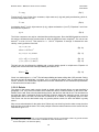
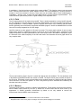
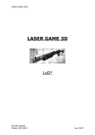
There is, however, no need to detect collisions in 3 dimensions since the robots can only maneuver in two.
Also, the robots used in the FIRA MiroSot leagues are in fact simple cube shaped objects as is illustrated
in figure 3.4. This rules out the need to detect collisions in the remaining third dimension because the ball
cannot for example bounce upwards on a robot.
Figure 3.4. 2D collision detection suffices
12
13
. The Mi20 robots were bought from the University of Dortmunt. Wheelspeeds were called PWM there.
. See paragraph 1.2.
20
Bachelor thesis – MiS20, the robotic soccer simulator
Hans Dollen
Wim Fikkert
3.3.8.1. Detecting
Collisions have to be detected between any of the ten robots and the ball. These objects can also collide
with the wall. Each object has to be compared with all the others to detect a collision. This results in having
to perform roughly
N2
(Eq. 1)
comparisons14. However, there is no need to check a collision seen from both objects in the same collision.
If object two collides with object three, object three will automatically collide with object two.
Collision detection is a very costly15 procedure to perform. This cost will therefore need to be reduced as
much a possible. To accomplish this, the detection algorithm(s) will have to be chosen to suit the task in
MiS20 best. There are a lot of different collision detection techniques which can be used. Almost all of
which originate from the gaming industry. A few of these collision detection techniques are16:
• Axis Aligned Bounding Boxes (AABB): using a bounding box around the object which encompasses the
entire object no matter what its orientation. This bounding box is aligned with the axes system. See
figure 3.5 for an illustration;
• Oriented Bounding Boxes (OBB): similar to AABB detection only the bounding box is aligned with the
objects local axis system which results in a closer fit compared with AABB;
• Bounding sphere: similar to AABB and OBB, a bounding sphere is used to encompass the object, see
figure 3.6 for an illustration;
• Binary Space Partitioning (BSP) trees: the 2 (or 3) dimensional “world” is divided into different
segments (partitions) in which objects are contained. When two objects are in different partitions they
cannot collide.
The latter, BSP trees, will perform well when objects are far apart and do not collide. When objects are
close to each other BSP trees are very performance costly which will turn it into a major bottleneck. BSP
trees are therefore not particulary suited for use in MiS20. The other three methods can be used however.
Since collision detecting is very CPU costly, the best method to detect collision is to divide the detection
into two (or more) layers of precision14. First we will detect if a collision might be possible between two
objects using a relatively inaccurate but fast algorithm. If a collision might be possible, a more accurate
test will be performed to detect if the collision actually has occured. If this test also passes, a collision will
have occured which will be handled as is described in paragraph 3.3.8.2. This approach will result in better
performance results. The second test can itself be expanded with a even more precise collision detection
algorithm if need be.
We will use AABB collision detection in the first level of detecting collisions. This is less costly compared
with the OBB and bounding sphere algorithms. The MiS20 AABB detection results in bounding boxes
which size equals to the diameter of the robots. Using this (set) size, the object will always be included in
the AABB.
Further, our AABB detection can be divided into two steps. First we check if an object can collide using the
difference between x axis locations of the two objects. If this difference is already too great to rule out any
collision, the y axis difference will not have to be checked. This will reduce performance of the collision
detection algorithm by 50% in most cases. Equation 2 illustrates the way the x and y axis can be checked.
x a −x b AABBsidelength
y a − y b AABB side length
where AABB side= 2⋅CUBE side
(Eq. 2)
14
. Gamasutra, advanced collision detection, see reference [W5].
. Costly regarding CPU use.
16
. See reference [W10].
15
21
Bachelor thesis – MiS20, the robotic soccer simulator
Hans Dollen
Wim Fikkert
OBB detection relies on having to calculate a local axis system for each object and then determining axis
differentials between objects. Bounding sphere collision detection is more CPU costly since it requires both
x and y locations for each object to be used in determining the distance between two objects. The AABB
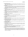
and bounding sphere detection algorithms are illustrated in figure 3.5 and 3.6 respectively.
Figure 3.5. AABB collision detection.
Figure 3.6. Bounding sphere collision detection.
The second level of detection consists of two techniques, one per shape (sphere or square). The OBB
algorithm would be imprecise for elaborate shapes. However, the robots can be viewed as being OBBs
themselves. We can therefore use OBBs to detect collisions between robots and robot-wall collisions.
Collisions with the ball can be detected using a bounding sphere representation for the ball. The OBBs and
the bounding sphere can be used simultaneously to conclude the second level of collision detection.
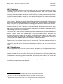
Figures 3.7 and 3.8 illustrate the two levels of collision detection used in MiS20. When a collision might
occur, the corner points of the objects involved will be tested to see if such a point resides in the other
object. If so, the line(s) that point is part of will be handed to the collision handling algorithm which uses
that information to react on the collision properly. In figure 3.7, these lines are AB and BC of object 6, and
EF of object 3. Figure 3.8 illustrates a collision between a robot and a ball. CD of the robot is the colliding
line. A collision between the ball with a wall and a robot with a wall is handled in a similar manner as is
illustrated in figures 3.7 and 3.8.
Figure 3.7. MiS20 robot versus robot collision
Figure 3.8. MiS20 robot versus ball collision
22
Bachelor thesis – MiS20, the robotic soccer simulator
Hans Dollen
Wim Fikkert
The time between two vector updates is about 33 milliseconds. This means that collisions in between
these time intervals have to be detected. The maximum robot velocity17 is 2,0 ms-1, and with AABB collision
detection, a box will be drawn around both objects. The box for the ball will be the same size as the box for
the robots. The dimension of such a box is:
half cubesize =0,0375 m
robot radius= 2⋅half cubesize
box length=box width=2⋅robot radius≈0,106 m
(Eq. 3)
No collision predictions will be needed in the time between two intervals; 0,0333 s. A predicition would be
needed only if the distance traveled by two objects, which would normally collide, is larger than twice the
AABB size; 0,212 m. The accumulated speed of a robot and the ball involved in a collision would need to
be 0,212 m / 0,0333 s = 6,36 m/s. Since the maximum speed of the robot is 2,0 m/s, the ball would have to
move 4,4 m/s. This speed is not obtainable by the ball in a robot soccer match18. We can therefore
conclude that the AABB collision detection algorithm will detect all possible collisions.
3.3.8.2. Handling
When a collision has been detected, the proper action has to be taken. This “proper action” depends on
the kinematical and dynamical representations of the ball and robots. For example, when two robots collide
their individual impact speeds, weights, orientations etc. will all effect the resulting robot vectors and
speeds after the collision. Because of the difficulties of robot versus robot collision handling, a rather
simple handling will be used. When two or more robots collide with each other, they will not drive through
each other, but will come to a stand. This robot versus robot collision handling will suffice for a basic
collision handling between robots.
In order to handle the collisions, a new coordinate system will be added. The normal axis is in the direction
of the line of collision and the tangential axis is perpendicular to n.
Figure 3.9. A new co-ordinate system
The collision handling will be done by using physic formulas19. The following equations will be used in order
to simulate realistic collisions:
mobject1⋅v object1 mobject2⋅v object2 =mobject1⋅v object1 mobject2⋅v object2
initial
initial
final
final
1
1
1
1
2
2
2
2
⋅mobject1⋅v object1 ⋅mobject2⋅v object2 = ⋅mobject1⋅v object1 ⋅m object2⋅v object2
2
2
2
2
initial
initial
final
final
17
(Eq. 4)
. From the Mi20 robot specifications.
. The maximum ball speed cannot exceed 2,82 m/s as can be calculated using equation 5 and match data
generated by the Mi20 team.
19
. See reference [B14].
18
23
Bachelor thesis – MiS20, the robotic soccer simulator
Hans Dollen
Wim Fikkert
In equation 4, m is the mass and v is the velocity. Using a coefficient of restitution e20, the new velocities
can be calculated resulting in equation 5, where n is the normal vector.
v object1 n=e1· m object2 · v object2 nv object1 n ·mobject1 − e · m object2 /m object1 mobject2
final
initial
initial
final
initial
initial
v object2 n=e1· mobject1 · v object1 n−v object2 n ·mobject1 − e · m object2 /m object1 mobject2
(Eq. 5)
The last step consists of transforming the n - t coordinate system back into the x - y system. The
coefficient of restitution e20 can be determined by equation 6 and will be calculated according information of
played matches21.
v object2 −v object1
e=
final
final
(Eq. 6)
v object2 −v object1
initial
initial
3.3.9. Kinematic models
Our project research question states when these kinematical and dynamical object models will be
sufficient to simulate a robot soccer match in an approximately correct way. Equations used in the chapter
have been found in reference [B13], [B15], [W13], or derived from known formulas. The ball and robot will,
logically, have different object models. However, both models will have to encompass friction with the
soccer field, object weight and object size. The equations below are used to determine speeds of an object
(either ball or robot wheel and robot) taking friction with the floor into account.
When the robots and the ball move on the field, as a result of wheelspeeds or a speed which they were
given after a collision, they will also have a kinematic model. This model represents the way they
maneuver on the soccer field. A number of things have to be taken into account when creating such a
model. First of all, friction. Friction with the ground will slow an object down. The same will go for air
friction. However, the latter may not be needed since its low value.
3.3.9.1. The ball
The ball used in a FIRA MiroSot middle league robot soccer match is an orange golf. This golf ball is round
of course, but it also contains a lot of dents distributed across its surface. These balldents make that we
will have to consider if we will simulate the ball as a perfect round sphere or if will simulate it as an
elobarate object. The latter would result in only a little deviation on the trajectory followed by a perfect
sphere across a plane22 at the the cost of a lot of CPU usage. The effort is not worth the benefits.
Figure 3.10. Ball friction model
Figure 3.10 illustrates the friction model which is to be used in the MiS20. Since the ball is to be considered
as a perfect sphere, it will also have its weight distributed evenly. This places the center of gravitational pull
in the center of the ball. This pull will result in a friction with the floor which results in a set deceleration for
the ball when no collisions occur. To determine this friction deceleration constant, the properties of the ball
have to be filled in equations 7 and 8.
. The coefficient of restitution models the loss of kinetic energy. If e = 1 you have a perfectly elastic collision and e
< 1 corresponds to a less than perfect collision.
21
. See chapter 6 for the value of the coefficient of restitution.
22
. This slight deviation has been observed in an actual soccer match.
20
24
Bachelor thesis – MiS20, the robotic soccer simulator
Hans Dollen
Wim Fikkert
F =umg
(Eq. 7)
Friction force F (in N), friction force constant u, object mass m (in kg) and gravity acceleration g which is,
on earth, always about 9.81 m/s2.
F =ma
(Eq. 8)
Acceleration force F (in N), object mass
be solved into equation 9:
m (in kg), object acceleration a (in m/s2). Equations 7 and 8 can
ug =a
(Eq. 9)
The friction constant u can only be calculated after performing tests. Since the MiS20 would be suited for
this task we will determine this constant later on when the MiS20 has been completed23. For now we can
assume24 a to be 0,12 m/s2. This results in u = 1,22*10-2. Equations 10 through 13 illustrate the new
velocity, x and y positions of the ball.
v t =v 0at
2
where a±0.12 m / s
(Eq. 10)
s t =s 0v t ⋅delta t
(Eq. 11)
x t = x 0s t ⋅cos
y t = y 0s t ⋅sin
(Eq. 12)
(Eq. 13)
The ball can also be affected by skidding and a certain rotation speed in multiple axes. Equation 14
displays the moment when the ball stops skidding and starts to roll.
delta t =
2v
7 ug
(Eq. 14)
Given is a certain speed v; 1,0 m/s2. The ball stops skidding and starts rolling after 0,352 seconds. During
this time the ball will decelerate a lot faster, as it is resisting the relative ease of rolling across a flat
surface. However, this deceleration equation has not been researched for the kinematical representation
of the ball as this is a basic model.
3.3.9.2. Robots
The robots in the soccer match can be viewed as simple cubical shaped objects, as was described in
paragraph 3.3.8. They have two wheels which enable the robot to maneuver about on the soccer field.
Robots, like the ball, have to be simulated having friction; with the floor and with the air. The two wheels on
the robot also have a mechanical friction to deal with; when the wheels are ordered to a stop, using new
wheelspeeds sent to the robot, the robot will not stand still in an instant. It will gradually come to a halt.
This friction can also be determined using only precise position results for which the MiS20 is greatly
suited.
Why not use a deceleration for the entire robot? When only one wheel is given the order to stop, the other
does not have to be told the same. This is the principle of how the robots maneuver on the soccer field, as
illustrated in figure 3.11.
23
. MiS20 is suitable for this task as it can read logged matches from file. The matches contain very precise location
and heading information which can be used to calculate the exact deceleration in m/s2.
24
. For this assumption, see reference [W13].
25
Bachelor thesis – MiS20, the robotic soccer simulator
Hans Dollen
Wim Fikkert
Figure 3.11. Two different robot wheelspeeds result in a new heading
The robot maneuvering will be simulated using equation 15. Both individual wheelspeeds are taken into
account combined with the current robot vector results in a new vector for that robot25. The distance
between the robot wheels is indicated by l, vrobot is the robot velocity and θ is the orientation of the robot.
v leftwheel v rightwheel
2
x t = x 0cosθ ⋅v robot
y t = y 0sin θ ⋅v robot
v
−v
θ t =θ 0 rightwheel leftwheel
l
v robot =
(Eq. 15)
The friction of the wheels with the floor will be simulated using equation 16. An entire robot can accelerate
with 1,0 ms-2. Since both wheels are needed to complete this acceleration, the acceleration per wheel is
equal to that of the entire robot. The wheel deceleration is 3,0 ms-2 for both of the wheels.26
v t =v 0±at
(Eq. 16)
Other aspects which are to be reviewed when constructing a kinematical model for a robot such as used in
the Mi20 team are: drifting and skidding. As with the ball, we have not researched drifting and skidding for
our kinematic representation of the robots, since this is a basic model.
25
26
. Vectors are mathematical vectors containing x and y locations, a heading and a timestamp.
. From the Mi20 robot specifications.
26
Bachelor thesis – MiS20, the robotic soccer simulator
Hans Dollen
Wim Fikkert
3.4. Control
The data model, partially described in paragraph 3.3, will stand at the base of the MiS20. It contains all
data which needs to be managed by the Mission Impossible Simulator. The way this data is managed will
be described in this chapter. User interactions can be derived from the requirements which where
described in chapter 2, using UML use cases. Figure 3.10 displays all interactions with the MiS20 the user
can undertake.
Figure 3.12. User use cases
Each oval in figure 3.12 indicates an interaction with the simulator which a user can perform. We also
created two groups of interactions (encircled in gray) because they are very similar to each other.
Figure 3.12 displays all user interactions which are possible with the MiS20. These also include
interactions which may not be implemented during this project. The reason why those interactions (“select
first person robot (FPR) cam” for example) are included in figure 3.12 is that, according to the requirement
stated in paragraph 2.1.5, the simulator must be designed in such a way that extensions are taken into
account when designing.
•
•
•
•
Selecting topdown camera mode:
The user selects the top down camera vantage point. The entire field is shown which results in
almost the same view which would be generated using the camera system.
Select First Person Robot (FPR) camera mode:
The user selects this camera mode after which an object (robot or ball) can be selected in the field
view. The camera is then set behind the selected object which results in a pursuit camera.
Select free camera mode:
The user selects this mode after which he (or she) can rotate, translate and zoom the camera
through the field view until another camera mode is selected.
Change collision detection mode:
When the user changes this mode via the menu the collision detection and handling functions will
either be or not be used according to the new setting when new vectors for the objects are
calculated. All objects can pass through each other and through the walls.
27
Bachelor thesis – MiS20, the robotic soccer simulator
•
•
•
•
•
•
•
•
•
•
•
•
•
•
•
Hans Dollen
Wim Fikkert
Change FIRA regulation mode:
When this mode is changed the FIRA regulations will be or will not be applied according to the new
setting. This will only be useful when an automated referee is created since a manual referee
applies the FIRA regulations himself.
Change AI mode:
It is possible to change the AI settings of both teams. For example a human team using joysticks
should be able to play against the AI team. To change this AI setting, the user will have to input a
new host address and port numbers. This host address and these port numbers represent the
location where the control system for this team is running.
Load a snapshot:
The user has the ability to load a snapshot from file. Such a snapshot contains all robot and ball
positions and will result in a new match situation. The loading of such a file results in the
repositioning of all objects in the field.
New snapshot:
When a user wants to create a new snapshot (for instance different starting positions for the
robots) this option is selected. The user can reposition all robots and the ball after the match has
been paused. It is then also possible to save the snapshot to file.
Edit a snapshot:
A snapshot is loaded after which the user can reposition the objects in the field. The snapshot is
saved in the same of in a different file.
Delete a snapshot:
A snapshot is selected by the user. The simulator then deletes this snapshot.
Save the current snapshot:
The simulator is halted when the user selects this option via the menu. The user can then save the
snapshot to file which is selected or created by the user.
Startup program:
The user starts the Mission Impossible Simulator program. However, the simulator will not begin to
simulate.
Starting or resuming the simulation:
When the user wants to start the simulation, this option is selected. If a situation is loaded already
this situation is resumed. If there is no situation loaded the user must select that situation first.
Stopping or pausing the simulation:
The user stops the simulator to make some adjustments such as changing an object's vector or
loading a different situation.
Shutting down the program:
This exits the program after asking the user if the current situation should be saved first. Log files
are written of the played match.
Manual referee calls:
The user selects an option such as free ball, free kick etc. by using the referee buttons. A situation
is loaded according to the option selected by the user. The options a user referee chooses are
determined by applying the FIRA rules.
Select an object:
The user selects an object in the field. It depends on the "mode" the simulator is in, for instance an
object can only be moved (its vector changed) when the simulator is paused.
Changing an object's vector (position, heading and speed):
The selected object's position, heading and speed are changed using the mouse in the field.
Load match:
When the Mi20 team has played a match this match will be logged when finished played. Mi20 will
need to review such a match using the simulator. The match is loaded from file after which it is in
the simulator. Actions such as a referee call will be displayed in the messaging part of the
simulator. It is still possible to pause the simulator but no changes can be made to the match (no
objects can be manipulated).
28
Bachelor thesis – MiS20, the robotic soccer simulator
Hans Dollen
Wim Fikkert
3.5. View
This paragraph will describe the design we created for the MiS20 Graphical User Interface (GUI). Multiple
aspects were taken into account; required user interactions, shortcomings and good features of the FIRA
simulator and various OVID27 aspects. OVID was not used to its full extent since the GUI provided by the
FIRA simulator is almost satisfactory and can be reused to some extent. Figure 3.11 displays the
completed MiS20 GUI design.
Figure 3.13. The Mission Impossible Simulator GUI design
The most important differences between the MiS20 GUI design and the FIRA simulator GUI are that the
MiS20 GUI design incorporates a manual referee application and object location information. Both of these
have been created using the user interaction diagram as seen in figure 3.12.
Various Human Computer Interaction (HCI) aspects have been used. The use of colors and contrast, and
positioning of GUI components are some examples. The complete analysis of the MiS20 GUI can be
found in our design document28.
27
28
. OVID; Objects, View and Interaction Design, see reference [B10] and glossary for more information
. See reference [B3].
29
Bachelor thesis – MiS20, the robotic soccer simulator
Hans Dollen
Wim Fikkert
3.5.1. Panels
The GUI design shown in figure 3.13 consists of five different panels as shown in figure 3.14. Besides the
panels described in figure 3.14, a menubar has been created with which the user can set numerous
settings such as turning collision detection on and off, setting new AI settings for both soccer teams,
managing snapshot files etcetera. For a complete list of menu items see our design document29.
Figure 3.14. The GUI panels
3.5.1.1. Time and scores
The time and team scores are displayed in the panel with the same name. The time is listed in minutes
and seconds whereas the number of goals for both teams indicates the score.
3.5.1.2. Soccer field
The soccer field panel displays a 3D representation of the soccer field in which the robots and the ball
maneuver. They are, as can be seen in figure 3.13, displayed in an unambigious manner to the user.
Colors of the robots are equal to those of the team they are part of. The ball, not being part of a team, will
be colored orange. Paragraph 4.3.1.2 describes which technique we will use to display the soccer field in 3
dimensions.
3.5.1.3. Buttons
The button panel enables a user to referee a match manually. A user referee can, using the FIRA
regulations, determine a set of five situations30 to assign to one of the two teams. He (or she) assigns a
free ball situation for example after which this snapshot is loaded. All objects (the 10 robots and the ball)
are then positioned according to the positions and heading properties found in the snapshot file.
29
30
. For the MiS20 design document, see reference [B3].
. A match situation is similar to a snapshot but is called “situation” in the FIRA regulations.
30
Bachelor thesis – MiS20, the robotic soccer simulator
Hans Dollen
Wim Fikkert
3.5.1.4. Object data
The bottom panel will display the exact robot and ball vector31 information and the object speed to the user.
This object speed consists of two wheelspeeds (one for each wheel) in case of the robots and consists of
one speed for the ball. The team colors of the robots are set as a background for each robot in this panel.
That way, a user can easily distinguish the robots. The table below displays the meanings of the
mnemonics.
Mnemonic
Stands for
Is listed in
x
X axis location of this object
meters
y
Y axis location of this object
meters
h
Heading or orientation of this object
0 through 2 pi
s
Ball speed
m/s
wL
wheelspeed of the left robot wheel
m/s
wR
wheelspeed of the right robot wheel
m/s
3.5.1.5. Messages
The messages generated by the MiS20 are displayed in the similary named panel on the right. An example
of such a message is a notification of the user that a team has to be chosen after a referee button is
pressed.
3.6. Communication interface
This paragraph will describe the way the communication interface with the Mi20 control systems has been
designed. First we will describe what this interface is exactly. Second, what methods can be used to
accomplish such an interface. And third, the actual design of this MiS20 program component.
3.6.1. Mi20
The Mi20 system has been implemented entirely in C. It is constructed to be a distributed system which
can be run on various machines without having to adjust much in the source code. For this reason, an
elaborate set of socket connections has been created which enable the various components of the Mi20
system to communicate with each other32. The sockets make use of mutexes to inform the receiver that
new data has been sent. The second unusual point about the sockets is that the server sends information
to a port on the client's host, and the client listens on its own port. So the Mi20 socket connections
“behave” differently from normal client-server sockets.
In chapter one, figure 1.1 illustrated which part of the Mi20
distributed system a simulator will replace. Figure 3.6 displays
the interface our Mission Impossible Simulator will have to
comply to in order to communicate succesfully with the Mi20
control systems.
Figure 3.15. The Mi20 communication interface33
31
. A mathematical vector contains x and y positions, a heading and a timestamp.
. Our design document includes a detailed description of this Mi20 component communication.
33
. A more exact communication interface diagram can be found in the design document, reference [B3].
32
31
Bachelor thesis – MiS20, the robotic soccer simulator
Hans Dollen
Wim Fikkert
3.6.2. Sending and receiving
What data actually needs to be sent and received? As described in figure 1.1, wheelspeeds are to be
received from Mi20 system three whilst snapshots are sent to system two. However, there is other
information which also requires to be sent: the game status (penalty kick for example), robot sensor
information (battery indication) and robot and ball odometrics (path which has been pursued). Figure 3.6
illustrates these information packages which are to be sent.
3.6.3. Java Native Interface
Since the interface with the Mi20 systems is programmed in C the interface of the MiS20 communication
component must also be in C. However, the requirements in chapter 2 state that the new simulator needs
to be build using Java. Therefore a way has to be found to enable Java to communicate with that Mi20
interface in C.
JNI34 allows Java to communicate with other program languages such as C or C++. JNI uses the JVM35 in
order to communicate with other programming languages. In the MiS20 JNI will be used as well, to interact
with the C++ socket communication classes. There are a few other possibilities to communicate with the C
interface, the choice of using JNI has been described below:
The possibilities enabling Java to communicate with C++ (and vice versa) are:
• Hexadecimal editing of received (C++) data and edit (Java) data which has to be sent;
• Corba: Java Corba and C++ Corba can communicate with each other;
• Java Native Interface: enables Java to communicate with a library of another language and vice versa.
Pro's and cons of hexadecimal editting:
+ Fast;
+ It might be more platform independent.
- Hexadecimal editing is relatively error-prone compared with native C++ sockets;
- Will data be received and sent as little or big endian36? This results in having to know if the processor
handles data as big or little endian;
- Hexadecimal editing will result in a great effort to program as well as difficulties to adapt, should the
Mi20 communication interface change;
- The communication part has to be written entirely. This means that the threads which receive and send
data must be implemented in a way that is fully compatible with the current C++ socket communication.
Pro's and cons of Java Native Interface:
+ The C++ communication can be used, the communication should not be error-prone;
+ Rather fast;
+ Adapting is not very difficult;
+ Can be implemented for more programming languages;
+ Not Error-prone whilst converting data from C++ objects to Java objects and vice versa;
- Debugging can be very difficult, because the error messages contain very little to no useful information;
- The library and all attributes in it are static. This lacks real OO programming37 in the library.
Corba is not an option because the existing system will not be changed for Corba usage, but it is a very
good mechanism to communicate between Java and C++. Also, hexadecimal editing is difficult to program
and is more error-prone than JNI.
In conclusion, JNI is the best option to enable communication between the existing Mi20 system
(programmed in C) and the MiS20 (which will be programmed in Java).
34
. JNI, or Java Native Interface see reference [B12].
. JVM, the Java Virtual Machine on which Java runs, see reference [W4] for more information.
36
. See glossary for more information.
37
. Object Oriented Programming.
35
32
Bachelor thesis – MiS20, the robotic soccer simulator
Hans Dollen
Wim Fikkert
The choice to use JNI, results in having to model the classes, which can be sent/received, in Java. The
existing C++ classes/structures are:
• Tsensor:
a sensor object which is situated on a robot and which uses a set battery voltage;
• Tgame_status:
describes the status of the game, which robot is in control of the ball etc.;
• Tsnap_shot:
contains all objects (ball and robots), team numbers, a boolean which indicates if
the camera recognition has detected the ball, a time stamp and a number;
• Tsnap_shot_object: indicates the position, orientation and color of an object such as the ball and a
robot;
• Todometrics:
contains robot wheelspeeds, location positions and orientation (vectors) and a
robot id;
• Twheel:
structure sent to a robot to actually control it: speed left, speed right, time stamp
and a number.
In order to design the use of JNI in the Mi20 simulator it is necessary to study how JNI works. In Java, a
native method interface can be written. These methods will be implemented in a native language, such as
C++. When a Java object calls such a native method, the JVM38 will load the native method in the native
languages, and apply the parameters on it. When the JVM calls the native method from the library, two
extra parameters will be given. The first parameter is an environment pointer, which can be used to call
Java objects, classes, methods etc in the native languages. The second parameter is the Java object
which has called the native method.
3.7. Decisions summarized
We will use two levels of collision detection to detect collisions between two (or more) objects and between
an object and a wall. The first will use AABB collision detection to determine quickly but rather imprecisely
if a collision might be possible. The second level will then use OBB collision detection to calculate the
exact collision between two objects (if there is one!).
The collision handler handles ball versus robot, and ball versus wall collisions rather well, in order to
simulate a realistic match. The robot versus robot and robot versus wall collisions will not be simulated
very realisticly, because of the complexity of this. The equations described in 3.3.8.2 will be used.
The kinematical model which will represent the robots and the ball uses object to floor friction to decelerate
an object. For this, a constant deceleration is assumed to be 0,1 m/s2.
We have used the MVC design principle to design our simulator program. It contains the three basic
components; model, view and control. However, it also contains an additional communication interface
component with the existing Mi20 programming.
XML has been used to store simulator data to files. Two file layouts are used, snapshot and match data
which are parsed by the Parlevink XML parser, available at the UT.
Vector information will be recalculated every 33 milliseconds. The GUI is then notified if changes have
occured. The vectors are only recalculated when the simulator is running. When stopped, the user can
reposition and re-orient objects. This is also stored in the object vector list.
Java Native Interface is being used in order to communicate with the existing Mi20 programming. This is
done entirely in the interface component of the MiS20 program. JNI will send snapshots to the Mi20
system and receive wheelspeeds from that system.
Java3D is used to represent the soccer field in 3D. It creates a scene graph which consists of two different
branches; objects and view. The 3D world design is based on the FIRA simulator GUI which was reused in
our GUI design.
38
. Java Virtual Machine, see reference [B14]
33
Bachelor thesis – MiS20, the robotic soccer simulator
Hans Dollen
Wim Fikkert
4. Implementation
This chapter describes the implementation phase of the Mi20 simulator project. Since the design divided
the simulator into four distinct components this chapter also describes those four components and the way
they interact. Figure 4.1 shows the MVC model which has been used in the design containing the four
different MiS20 components. The components represented in this figure are described in this chapter,
much in the same way as in the previous chapter. We will first state the design changes we made,
followed by the model, view, control and communication interface implementation descriptions. The
chapter concludes with a performance issues paragraph in which performance problems and their
solutions are described. The Java classes in this chapter are written in italic. The default Java classes'
javadoc documentation can be found on the Java 1.4.1. API javadoc page1. The MiS20 Java classes
javadoc documentation can be found on the MiS20 homepage2.
Figure 4.1. Applied MVC model
4.1. Design changes
This paragraph describes what alterations have been made to the simulator design as seen in the previous
chapter. The design divides the MiS20 program into four separate components3; model, view, control and
communication. The exact implementation of these components is described in the following paragraphs;
4.2 through 4.6. Suffice to say, we made no very extensive changes to our design.
4.1.1. The referee
In a match, the referee calls situations from the FIRA regulations, such as free kick, penalty kick and so
on. In the MiS20 design the referee object was positioned in the model component where it could
manipulate match data. However, since a referee undertakes actions a better position for this object would
be in the control component. We also created a Referee interface which all new referee objects in the
MiS20 must implement.
4.1.2. Settings
In our design we had a number of classes which contained static data. For example, the SimField class
which contains all data concerning the soccer field. Since that data is not likely to change dynamically we
removed all get and set functions which were designed and we made all settings concerning the field
public static final variables. As described in paragraph 4.6, this also enhances performance for the MiS20
program. An extra class has been created which contains all static information for the Mission Impossible
Simulator. This SimSettings class also does not need to be instantiated.
4.1.3. Popups
We did not design the use of popup windows in the simulator. These are needed when asking the user to
decide which team has to benefit from a certain referee call for example. Also, popups are needed to
adjust settings such as the host and port settings in the MiS20 program communication component. We
created a class, the GuiPopupGenerator class, which has various methods to create and display popups to
the user. The actual implementation of this class can be found in paragraph 4.3.
1
. See reference [W7] for the Java 1.4.1. API javadoc page.
. For the MiS20 homepage see reference [W12].
3
. The MiS20 design can be found in reference [B1].
2
34
Bachelor thesis – MiS20, the robotic soccer simulator
Hans Dollen
Wim Fikkert
4.1.4. Messaging
The message panel, as seen in the design document, contains a list of messages which are displayed to
the user. However, to record the messages of a specific match the SimMatch class will also have to record
the messages displayed to the user in that specific match. Therefore, we added a list of messages to the
SimMatch class. When a new message is added to that list, the GUI component which displays those
messages is informed. See paragraph 4.3.1.4 for a more detailed explanation.
4.2. Model
The model component stands at the heart of the simulator. It contains, coordinates and administrates all
data concerning the simulator; matches, object vectors and so on. The SimAdministrator class manages
match data via its match object. This object contains all data associated with a match (teams, ball
etcetera). The designed and implemented UML class diagram of this data model is stated in appendix C.1.
4.2.1. Files
As seen in the analysis and design chapter (chapter 3), XML is used to store and recover information
regarding the Mi20 simulator; snapshots and match logs. The XML parser included from the parlevink.xml
package was used to implement this4.
The Mi20 simulator administrator (the SimAdministrator class5) has a link to an object factory6. When
reading a file from disk, this factory calls upon an implementation of the parlevink.xml.XMLTokenizer class.
This parser reads the requested snapshot or match from file and returns the required object. When saving
a match or snapshot to disk, a PrintWriter from the default java.io package is used. This object writes a
String to a given File (also from the java.io package).
In a snapshot XML file each object has a vector which indicates its position and its heading. The code
sample below displays this snapshot vector for an object. The entire snapshot file layout is described in our
implementation document7.
<object id="1" x="0.06500015" y="0.9" h="0.0" />
4.2.2. Propertychange events
Chapter 3 describes that object vectors only need to be updated when they have been changed.
Whenever a vector has been changed, the GUI is notified using Java property changes. An event is fired
by the object (a SimObject instance; SimRobot or SimBall) from the model when its vector has changed.
This event is used by the view components listening to this object. There are two GUI components
listening to each individual SimObject; the 3D representation of that object and the object vector data panel
representing that object. The latter is a part of the object vector panel described in paragraph 3.5.1.4. Pro's
for using property change events are:
• Implementation of the MVC model in which Model and View are separated;
• More view objects can listen to one data object;
• When the data object fires a property change, the view objects method propertyChanged has been
called, which can call the repaint method, because it is only a view;
• Also works for Java3D;
• A fired property change contains the old and new data.
We do not use Java Observers instead of property changes since we have a lot more experience with the
latter and no major performance differences are present8.
A problem arises when a match is loaded from file. The objects are replaced by new ones, from the new
match object loaded from file. The (GUI) property change listeners of that object would be lost. This
problem is solved by moving those listeners from the original object to the new version of that object.
4
. The parlevink.xml parser is a SAX XML parser which reads and returns a tag at a time.
. Java MVC administrator class, complete description can be found in reference [B8].
6
. An implementation of the factory design pattern, see reference [B6] for more information.
7
. See reference [B4] for the MiS20 implementation document.
8
. See reference [W11] for information on performance from the Java programming manual.
5
35
Bachelor thesis – MiS20, the robotic soccer simulator
Hans Dollen
Wim Fikkert
4.2.3. Collisions
This paragraph describes how collision detection and handling is implemented in the MiS20.
4.2.3.1. Detection
Collisions can occur between multiple objects and between objects and one or more walls. These
collisions are detected using two levels of collision detection as described in paragraph 3.3.8. The first
level of detection uses AABBes for each object. An easy check can be performed to test if another object
is colliding with a test object. This has been described in paragraph 3.3.8. If the first collision detection
algortihm returns a possible collision, a second, more precise detection, is performed. If this test also
results in a collision, the collision is handled as described in paragraph 4.2.3.2.
The first level of detection uses equation 2 as stated in paragraph 3.3.8.1. The following code sample
illustrates the implementation of this equation. The SimSettings class has a number of static class
variables which are calculated only once, on program startup. This also improves the performance of this
algorithm.
float fDeltaX = Math.abs(oA.getVector().x() - oB.getVector().x());
if(fDeltaX < SimSettings.fROBOT_COLLISION_SPHERE_RADIUS +
SimSettings.fBALL_COLLISION_SPHERE_RADIUS
)
{
float fDeltaY = Math.abs(oA.getVector().y() - oB.getVector().y());
if(fDeltaY < SimSettings.fROBOT_COLLISION_SPHERE_RADIUS +
SimSettings.fBALL_COLLISION_SPHERE_RADIUS)
{
/* ... a collision might be possible! Go to level 2 detection ... */
}
}
The second level of collision detection uses lines to detect collisions. These lines can be drawn on a
TestFrame by adding them to the frame that has been made for testing. The robot consists of four lines,
one per side (left, front, right and back). A collision between two robots occurs when one or more lines of
the first robot intersect one or more lines of the second robot. To detect collisions between objects within
the time interval of 30 ms, a line will be drawn from the robot to a point which is the point at which the robot
will be on the next update.
Ball collisions will be detected by checking if the distance from the center of the ball to the wall (which is in
fact a line) or robots' line is smaller than the ball's radius. Also for the ball, detecting of collisions between
updates will be done by drawing a line to the next position, and checking if the ball collides with an object.
4.2.3.2. Collision handling
Collision handling has been implemented using the lines described in the paragraph above. Even the
equations described in previous chapter have been used and thus implemented. The handling handles
collisions for robot versus robot, robot versus wall, ball versus robot and wall versus ball. The latter two will
be handled rather precisely.
4.2.4. Kinematic models
This paragraph describes the way of simulation of the robots and the ball in MiS20.
4.2.4.1. The soccer ball
The ball will be simulated as described in the previous chapter. The formulas described in the previous
chapter have been implemented. A deceleration factor has been added to the SimBall with which the ball
will decelerate every update.
36
Bachelor thesis – MiS20, the robotic soccer simulator
Hans Dollen
Wim Fikkert
4.2.4.2. The robots
The robots will be simulated as described in the previous chapter. The SimRobot contains a maximum
deceleration and acceleration. The robots always accelerate or decelerate at max to its target speed. The
acceleration and deceleration variables have been retrieved from real world data of matches played by the
Mi20 team. The acceleration factor is about 1,0 m/s2 and the deceleration factor is about 3,0 m/s2, which
includes friction with air and floor. Other formulas which have been used have been described in the
previous chapter.
4.3. View
The view consists of several Java graphical packages, Java Swing, Java AWT and Java3D. The resulting
GUI of the Mission Impossible Simulator includes all designed GUI components as described in the design
and analysis chapter (chapter 3). Figure 4.2 displays a screenshot of the MiS20 in action.
Figure 4.2. A MiS20 screenshot
4.3.1. GUI components
Figure 4.2 displays a screenshot of MiS20 completed. It consists of various panels, each displaying
different information to the user. Each of the panels displays another set of information to the user as we
already described in paragraph 3.5.1.
4.3.1.1. Menu
The dropdown menu in the menubar implements the class JPopupMenu9. Since such a menu can result in
having to program a great deal of the same source code the menu creating process has been eased by
implementing various functions which reuse source code.
9
. Is a part of the java.swing package, see reference [W7].
37
Bachelor thesis – MiS20, the robotic soccer simulator
Hans Dollen
Wim Fikkert
A makeMenu(..) function has been created which creates a JMenu9. This function creates a tree structered
menu. It has a parent menu item (which enables recursive use of the makeMenu(..) function) and has a
number of menu items located in an array. These items can be a JMenu object in itself created with the
makeMenu(..) function. Also, a target has been added which is an ActionListener implementation10. The
created functions (and classes) result in a great flexibility of the dropdown menu.
4.3.1.2. Field
The 3D representation will be made using Java3D. There is another alternative to using Java3D; OpenGL
for Java. OpenGL for Java has however, a few major disadvantages. The most important ones being it not
being standardized or widely available, OpenGL exposes inner details of the rendering process which
would significantly and unnecessarily complicates the MiS20 program. Java3D is standardized for use with
Java and it is easily integrated into our GUI design.
Java3D constructs a scene graph of a 3D world (or scene). This scene graph consists of one (or more)
object branch group(s), containing all objects in the scene, and a view branch group, containing all view
related components. A simple representation of the Scene Graph used in the MiS20 is displayed in figure
4.3. Because of the relative simplicity of the 3D world used in this simulator the scene graph will be not
very complex either.
Figure 4.3. Java3D Scene Graph used in the MiS2011
The two main branch groups in figure 4.3 contain the objects and view attributes. The view attributes used
in the Mission Impossible Simulator are default to Java3D. The object branch group contains all objects in
the 3D scene. This branch group can be divided into two separate groups; the static field and the dynamic
robots and ball. The latter are dynamic in such a way that they will be translated and rotated by the
simulator (and user) at runtime.
4.3.1.3. Buttons
The button panel contains a number of JButton implementations. These buttons all have an ActionListener
which handles button presses by the user. A button has a white border and title which make up it's
appearance. A JButton generates ActionEvents by default so we only needed to connect the
ActionListener from the MiS20 control component.
10
11
. See chapter 4.3 for information on how ActionEvents are used in MiS20.
. Simplified version of the scene graph, see design document (reference [B3]) for more details.
38
Bachelor thesis – MiS20, the robotic soccer simulator
Hans Dollen
Wim Fikkert
4.3.1.4. Messages
The messages panel displays system messages to the user. Since a great number of such messages can
be generated by MiS20, the user needs the ability to scroll back in those messages. A TextArea has been
used to add a scroll bar for the user to scroll back. Also, a timestamp is added to each message prior to
sending it to this panel. This timestamp indicates the current playtime of the match which starts at 0.
4.3.1.5. Object data
This panel displays all vector information on the robots and the ball. The object data panel consists of 11
subpanels which each display a single object in the soccer field. Each of these subpanels is a property
change listener as described in chapter 4.2.2 and updates its data on receiving a PropertyChangeEvent.
4.3.1.6. Time and score
This panel contains the playtime of the match and the goals per team. The time is displayed in minutes
and seconds.
4.3.2. Heavyweight components
The Java3D package used is a non-standard package provided by Sun, the creators of Java. Combining
the use of default Java packages and the Java3D package leads to some difficulties since Java3D uses
mainly heavyweight components whilst Java AWT and Java Swing uses lightweight components12.
One of the places in the MiS20 where this problem occurs is in the menu, which has to be drawn on top of
the (Java3D) heavyweight 3D soccer field panel. The problem was solved simply by changing the
lightweight property of the JPopupMenu to heavyweight. This results in the drop down menus from the
menu bar being drawn on top of the 3D field representation.
Another problem occurs regarding heavy- versus lightweight panels when the MiS20 window is resized (to
full screen for example). A specific size for each of the panels has to be set. For this reason, all panels in
the GUI override the basic setSize(int, int) method of the JPanel class.
4.4. Control
This simulator component handles all user interactions with the program. It catches user actions such as
mouse clicks, keys pressed etc. and informs the simulator that the user has taken some action. For
example, when the user presses on the “start simulator” button in the GUI the control component informs
the model component that the user wants to start the simulation. After a few checks, the model component
enables the communication with the Mi20 control system which sends the robot wheelspeeds.
4.4.1. Action events
The user interactions are handeled using ActionEvents13. These are fired by various view components
such as the referee buttons, described in paragraph 4.3.1.3. When such an event is fired, the
corresponding action listener catches this event and handles it. When the referee button “goal kick” is
pressed for example, the action listener calls the “goal kick” function of the referee object.
4.4.2. Java3D picking
Not all user interactions are included in this control component, contradicting the MVC model. Java3D
requires picking behaviors to be implemented in its scene graph.
To move and rotate the Java3D objects on screen, 2 different behaviors have been used. These two
behaviors are the PickRotateBehavior and the PickTranslateBehavior. If pick reporting of a Java3D object
has been enabled, it can be translated and rotated.
12
13
. Java heavyweight components are displayed on top of lightweight components, see reference [W6].
. The application of action events in a Java program are described extensively in reference [B11].
39
Bachelor thesis – MiS20, the robotic soccer simulator
Hans Dollen
Wim Fikkert
The behavior reacts on mouse events, and calls the Java3D object method setTransform(Transform3D) to
rotate or translate the object. The drawback of the PickRotateBehavior is that it rotates the object in all
directions, while the robots and ball may only rotate along their y-axis. The drawback of the
PickTranslateBehavior is that it will move objects in an x- and y-direction, while the robots and ball may
only move in an x- and z-direction. For these reasons, the setTransform has been overwritten. This
overwritten method converts the y-movement into a z-movement, and removes rotations around the x-axis
and z-axis.
[
cos
0
−sin
0
0 sin x
1
0
y
0 cos z
0
0
1
]
(Eq. 17)
The code below illustrates how the information from the matrix will be used in order to create a new
SimVector. The Transform3D contains the matrix with new positions, which are the old positions with the
delta position or heading added. De y rotation will be retrieved from the matrix stated in equation 17.
public SimVector getNewSimVector(Transform3D oTransform3D)
{
Transform3D oldTransform3D = new Transform3D();
SimObject oSimObject = getSimObject();
if(oSimObject !=null)
{
float fHalfSize = SimSettings.fHALF_CUBE_SIZE;
if(oSimObject instanceof SimBall)
{
fHalfSize = SimSettings.fBALL_RADIUS;
}
SimVector oSimVector = oSimObject.getVector();
float[] matrix = new float[16];
oTransform3D.get(matrix);
float newHeading = ((float)Math.asin(-matrix[8]);
if(newHeading<0)
newHeading+=(2*SimSettings.fPI);
// z movement is the y-movement the object will do
// which is the new y position – old y position
float fDeltaZ = matrix[7]-fHalfSize;
SimVector oNewSimVector = (SimVector)oSimVector.clone();
oNewSimVector.setHeading(newHeading);
oNewSimVector.setX(oSimVector.x()+fDeltaX);
oNewSimVector.setY(oSimVector.y()+fDeltaZ);
return oNewSimVector;
}
}
return null;
4.5. Communication interface
As described in the previous chapter (analysis & design), JNI has been used to establish communication
with the existing Mi20 programming. The current C communication uses mutexes to signal the receiver
when new data has been sent. The senders and receivers are both threads. The MiS20 Java
communication interface component also consists of send and receive threads. These threads contain a
superclass, respectively CommSendStub and CommReceiveStub, which contain the native functions
interface. These native functions are the sent, receive, start, and destroy functions.
On starting a send or receive thread, a C++ thread will be constructed, which actually can send or receive
data. Passing data from Java to C++ will be done according the native functions, and passing data from
C++ to Java will be done according to a retrieved Environment pointer, which is a pointer to the JVM.
Changing from port and host can be done by deleting the old sender and creating a new sender on a
specific host and port. The port for receivers to listen to can also be changed. The difficulty with JNI is that
a static library has to be used, because of this every sender has to be registrated by the library. Every
40
Bachelor thesis – MiS20, the robotic soccer simulator
Hans Dollen
Wim Fikkert
native function must check if a sender or receiver has been started yet, or if not, it must wait till the sender
or receiver has been started. Further, some problems, for example with thread priority have occured.
Receiving and sending objects works correctly, but on deleting a sender or receiver an error occurs
because of the receiver or sender thread from the Mi20 communication system.
4.6. Performance
This paragraph will state all performance related improvements we made for MiS20. Profiling is discussed
followed by the use of collections of objects. Next we describe the use of StringBuffers followed by using
cloned objects.
4.6.1. Profiling
Profiling is a technique which indicates where bottlenecks are in a program. Java has a built-in method to
profile a program. By using the -Xrunhprof parameter when running a program an elaborate profile of that
program is created. These files can be distilled by various programs which offer a graphical view which
indicates the problem areas in the profiled program14. A Java program is profiled like this:
java -Xrunhprof:cpu=samples,depth=6,thread=y
RobotsoccerSimulator
The values given along with the -Xrunhprof parameter indicate how to profile the program. The result is a
huge file (easily over a few megabytes in size) which contains all method calls down to the user indicated
depth level (in this case, six). The table below displays where the bottlenecks in the MiS20 program were.
Only the top 10 methods are displayed here. To visualize this a profile analysis tool, PerfAnal15, was used.
It does not generate a graph but offers a structured representation of the program's profile. The
percentage column is the percentage of total CPU cycle usage, the calls are the number of calls which
were resposible for that percentage:
percentage
67.93%
20.41%
5.83%
0.35%
0.30%
0.25%
0.22%
0.17%
0.12%
0.12%
calls
2726
819
234
14
12
10
9
7
5
5
function
CommReceiveStub.startReceiverThreadOnSpecificPort
CommSendStub.startSendThreadOnSpecificPort
sun.awt.motif.MToolkit.run
sun.awt.X11Renderer.doFillRect
javax.media.j3d.Canvas3D.swapBuffers
javax.media.j3d.Canvas3D.setModelViewMatrix
javax.media.j3d.Canvas3D.callDisplayList
javax.media.j3d.Canvas3D.createContext
javax.media.j3d.RenderingEnvironmentStructure.getInfluencingAppearance
java.lang.Thread.yield
The main botlleneck functions are to be found in the JNI communication component of the MiS20 program,
using almost 90% of the cpu cycles. Both sending and receiving of data for the MiS20 program can be
regarded as a bottleneck. The usage of Java3D is not very performance costworthy so we can ignore
improving performance there, it uses only 1% of the available cpu cycles.
The sending method used in the communication process converts SimSnapshot instances to
CommSnapShotObjects which are sent to the Mi20 control system. This translation process also requires
mirroring of vectors16 when the Mi20 team is playing from the other half of the soccer field (default is left).
This results in overhead which can be reduced to when applying a fast accessable data structure. This is
described in paragraph 4.6.2.
14
. Profiling is described on the Java website, see reference [W1].
. PerfAnal, or Performance Analysis tool can be found on the Java website, reference [W1].
16
. Mathematical vectors, not to be mistaken by instances of the java.util.Vector class.
15
41
Bachelor thesis – MiS20, the robotic soccer simulator
Hans Dollen
Wim Fikkert
4.6.2. Collections
The MiS20 data model contains a lot of information. A match has two teams, each containing five robots.
These robots, as well as the ball, which is also contained by the match, have a list of positions called
vectors17. The parent class for the ball and robot, the SimObject class contains this vector collection (of the
SimVector class). However, there are various approaches on how to actually implement such a collection.
One thing to take into account is that the list of vectors will be approximately 18000 units long. There are
four good candidates; LinkedLists, ArrayLists, Vectors and arrays of objects18, all of which can be found in
the java.util package.
LinkedLists are very robust in their usage, they provide in size methods, as well as adding, replacing,
iteration functions. However, they do not implement the RandomAccess interface. This interface ensures
that a list can be searched very fast using random access to the list. A good argument to use LinkedLists
though, is they have very good performance when managing data in the front to middle sections of a list19.
A second option is the usage of ArrayLists. These lists implement the RandomAccess interface which
ensures very fast list access. However, ArrayLists are slow compared with LinkedLists when managing
data in the front of the list since all objects have to be replaced in the list. LinkedLists just change their link
to the following object in the list in comparison.
Third, Vectors are a good alternative. They also implement the RandomAccess interface from the java.util
package. However, Vectors have overhead whilst it uses synchronized functions. This means it is
threadsafe at extra cost. When viewing the design it becomes clear that there is no need to synchronize
the objects since only one instance may alter any lists, the SimAdministrator instance. Also, when a Vector
instance has outgrown its original size it automatically allocates twice its current size for future use. In
comparison, ArrayLists add only half their size which results in better performance.
Fourth, the use of arrays to store objects is not to be recommended. They have a static length which can
only be extended by creating a new array. This results in too much overhead.
Taking all the pro's and cons into account, the best alternative to choose is the use of ArrayLists for the
vectors.
4.6.3. StringBuffers
A second performance issue is the use of String instances. Strings are very often appended using simple
“+” operators. These can be relatively costly when used in great numbers.
An example of the use of Strings in the MiS20 program. Every time a full second has elapsed when a
snapshot is created and sent to the Mi20 control system20, the simulator time (in the GUI) is updated using
a property change event. The value sent along is a String containing the new time. This String is
constructed using the toString() method of the current SimTimestamp class instance. This function calls
five “+” operators to create the String.
A better and more effective way to accomplish this task is to apply a StringBuffer. As its name states, it
uses buffering to improve performance aspects.
17
. Mathematical vectors, not to be mistaken with instances of the java.util.Vector class.
. The Java 1.4.1 API describes all Java API classes in great detail, see reference [W2].
19
. Perfomance issues for Java programs are described in great detail in reference [W3].
20
. See reference [B1] for more information on the individual components of the Mi20 system.
18
42
Bachelor thesis – MiS20, the robotic soccer simulator
Hans Dollen
Wim Fikkert
4.6.4. Object creation
Every time the vectors are updated using the update thread, a new SimSnapshot containing new
SimVectors for all objects is created. Normally constructors would be used to create a new class instance.
However, using a constructor to create a new object is relative costly compared with the copying or cloning
of an object.
Arrays can be copied using the System.arrayCopy() method. Objects can override the clone() method in
the Object class. There are then two approaches to implement such a clone() function; using a shallow or
a deep clone. By calling the clone function of the Object class, a bitwise copy of the object is created, in
other words, a shallow clone. References unique to a specific class instance are to be cloned as well in the
MiS20 program. How cloning works is explained in our implementation document21. We created a simple
clone versus constructor test to measure performance differences between the two. This program can be
found in the appendices of our implementation document. The results are:
constructor loop took: 131msec
clone loop took: 51msec
The results on the previous page prove that cloning is less costly compared with constructor use. The
reason that cloning is faster and less costly than using a constructor is that the latter requires calculation of
the amount of memory to be allocated. This process is bypassed when cloning as the amount of memory
needed is already known. We therefore use cloning as much as possible in the MiS20 program.
Another point to be taken into account can be found in the XML parser we wrote for the MiS20 program.
Here, a file is parsed and each XML tag is returned as a java.util.String. Since various pieces of match
information are to be considered as a float, int or other numeric data we will have to convert these Strings
to their numeric values. For example a number 0 is to converted to int. We can create a new Integer class
instance of which we call the intValue() method. This returns an int value 0 which we wanted. Since
constructors are slow compared to static class methods for which no class instance has to be created we
are better off using such static methods. The results of a small test program we created:
constructor loop took: 128 msec
static function loop took: 41 msec
This test, and the cloning test together prove that constructors are to be avoided whenever possible.
4.7. Implementation summarized
The MVC model has been used to implement the MiS20. The program is therefore suitable for reuse and
expansion. Using the design described in chapter 3 we implemented the collision detection and handling
algorithms in such a way that they can be improved easily.
No major design changes have been made. The referee object was moved from the MiS20 model
component to the control component since it undertakes a great deal of (user driven) actions. We created
a single class which contains a lot of data which is reused and static for the entire simulator. This will
enable future developers to adjust settings easily.
XML files are used to log snapshot and match data of the MiS20 to disk. An available parser at the UT,
called parlevink XML has been used and altered to accomplish a working XML file parser.
Property change events are being used to enable communication between the various components of the
MiS20. For example, the GUI is updated using property change events fired from the model it represents.
The GUI has been implemented in five separated panels, together they represent the MiS20 data to the
user. The soccer field is represented using Java3D to display a three dimensional view of the soccer field.
JNI has been used as an interface between Java and C++. The C++ part contains the communication with
the existing (Mi20) system. The problem with using JNI is that a static library has to be created and used.
21
. For the MiS20 implementation document see reference [B7].
43
Bachelor thesis – MiS20, the robotic soccer simulator
Hans Dollen
Wim Fikkert
This generates some concurrency problems which had to be solved. Further, on destroying a
communication thread, the thread would not always be destroyed, but will sometimes crash. Sending and
receiving of data with the Mi20 control system works correctly.
Numerous performance enhancements were made using the results of a profiling session of the MiS20.
The type of used object collections has been altered to ArrayLists, and objects are created using cloning
instead of constructors. Cloning decreases object creation times by almost 67%.
Concluding this chapter, a developers manual has been written for future developers to use in reusing of
and expanding upon the MiS20. This manual can be found in our implementation document as well as in
appendix C.
44
Bachelor thesis – MiS20, the robotic soccer simulator
Hans Dollen
Wim Fikkert
5. Testing
This chapter describes the test methods used and results generated in our MiS20 project. MiS20 is divided
into four separate components which we will use to structure this chapter as well; model, view, control and
communication interface. Various test methods have been used to test MiS20; function testing, fault based
testing and functionality testing1. These test methods are described in our test document2.
5.1. Model
The model component contains all essential data concerning the MiS20 program; matches, snapshots,
object vector lists etc.
5.1.1.Variables
We have tested get and set functions for correct returning and setting of variables. We used function
testing to check if these functions performed correctly. Some variables fire property changes whenever its
value has been altered by another object. We tested these property change events by adding
System.out.println(String) statements in functions which fire and functions which receive these events.
Further, we created a developers menu for the menubar of the GUI which enabled us to test which data
was present in the model at times of our choosing.
5.1.2. Object creation
As described in paragraph 4.6.4, we use cloning to increase performance when creating new objects. We
have tested these methods using function testing to ensure they return the same result when a constructor
would have been used. We used the equals(Object) methods of the objects which were cloned to check if
the objects were equal to their original object version. Also, we ensured ourselves that such a cloned
object does not contain any references to the original object's variables by comparing the memory
locations of the variables with their cloned counterparts.
5.1.3. XML parser
We used a modified version of the XML parser available from the UT (parlevink XML) for parsing our XML
files. It can parse two types of files; logged matches and snapshots. Function and fault based testing were
applied to test the correct functioning of the XML parser. The parser also includes write functions which
can write these file types (matches and snapshots) to file using the XML layout as described in our
implementation document.
5.1.3.1. Writing
Using function testing we wrote bogus snapshots and matches to file. We checked the resulting file to see
if it was in the correct XML layout we designed in our design document. A bug was discovered when trying
to log a match lasting longer than 2 minutes. We tried to create a single String object containing all
information for the match file. However, we did not realize that a String has a maximum length determined
by the system memory size MiS20 runs on3. We therefore updated the writing process to write a stream of
data to file; every time we have another set of information to be logged it is written to file.
5.1.3.2. Reading
Using the parlevink XML parser we tested correct snapshot and match files which resulted in no errors.
We then tried parsing files containing deliberate errors which resulted in program failure. We added some
tests to check for valid data and this bug was solved.
1
. See glossary for more explanation on these test methods.
. For the MiS20 test document see reference [B8].
3
. For more information see the Java homepage, reference [W4].
2
45
Bachelor thesis – MiS20, the robotic soccer simulator
Hans Dollen
Wim Fikkert
5.1.4. Collisions
This paragraph describes the test results gained by testing the collision detection and collision handling
techniques we applied. We used functionality testing to test the various algorithms we created.
5.1.4.1. Detection
In order to test the collision detection, the robots were positioned on places with different known collisions.
Testing robot versus wall collision detection was done by checking if the individual robot sides intersect
with the wall; both of which are represented by two dimensional lines. Further, robot versus robot collision
detections were tested in a similar way; we checked if robot sides intersected each other. These
intersection were predetermined so we could simply check if they detected a collision when there should
be one and the other way around. Robot versus ball collision detection has been tested by calculating the
distance of the ball center perpendicular to each of the robot sides. If the resulting distance is larger than
the ball radius a collision has occured. These results were checked to see if they were correct.
Further collision detection was tested by rolling the ball at high speed to the wall, and by rolling the ball to a
moving robot. Also robot versus robot collision detection when robots are moving was tested by driving the
robots towards each other, or letting robots move to the same place.
5.1.4.2. Handling
Collision handling has been tested by simulating ball versus robot collisions and checking if the collisions
were handled realistically. Handling ball versus wall collision has been tested by rolling the ball to the wall
and checking if the angle in equals angle out. On robot versus wall collisions, the robot's velocity must be
zero, also for robot versus robot collisions the velocities of both robots must be zero.
5.1.5. Kinematic models
This paragraph describes how we tested the simulation of the objects. It describes what results were
gained from measuring the ball and wheel decelerations. The kinematic models have been tested by
performing tests with the real objects (ball and robots) and comparing those results to the results
generated by the MiS20. For example, by rolling the ball and checking how long it take before it has
stopped. Because of the friction force which has been obtained from the real world, and the physic
equations which have been used, the friction will be simulated correctly.
5.2. View
The MiS20 view component was tested per individual GUI panel. We mainly used functionality testing to
determine if the correct actions provided by the user resulted in the correct system actions and vice versa.
The only major problem we located was found when resizing the GUI. We had to create a resize method
manually since Java3D gave us trouble. This function had some difficulties redrawing panels in the correct
position. We therefore added a test to check the width and height of each panel after resizing which
guarantees the panels have the correct sizes. For the rest, we only found some small errors in the GUI
which are described in our test document4.
5.3. Control
This MiS20 component handles user interactions and the referee object. The latter is controlled by the user
who referees a soccer match via the button panel of the MiS20 GUI.
5.3.1. User interactions
Whenever a user presses a button in the GUI he (or she) triggers an ActionEvent which is fired by that
button. This event is caught by the control component which takes the appropriate action. This is done by
comparing the name of the action event in a number of if statements. This is relatively error-prone and
during testing often resulted in our not being able to determine which action event was fired. We therefore
listed all action event names in the SimSettings class as public static variables. The ActionEvent now
contains a static name which can easily be checked:
if(oActionEvent.getName().equals(SimSettings.sA_NAME)) { .. /* do something */ .. }
4
. See reference [B8] for the MiS20 test document.
46
Bachelor thesis – MiS20, the robotic soccer simulator
Hans Dollen
Wim Fikkert
5.3.2. The referee
The referee object will handle all referee calls which are made. Examples are: free ball, goal kick and
penalty kick calls. These referee calls all use a different method of the referee object. We tested these
methods using functionality testing to ensure that they would perform as expected. When calling a free ball
situation the wrong free ball situations were loaded. When the ball was in the upper left corner, the free ball
situation for that upper left quarter should be loaded. However, the lower left situation was loaded. We
resolved this bug by updating the checks made to test where the ball is located when calling the free ball
situation. When the referee has determined that a goal has been scored by a team the start positions are
loaded. However, the goal would not be counted for the opposing team. The check which detected a
scored goal for that team was fixed.
5.4. Communication interface
The simulator has to communicate with the existing system using the C communication. JNI has been
used to let Java communicate with the C communication. To test the communication with the existing
system, test classes have been written. These classes send or receive data using the communication
which methods which have been used in the simulator. Also C(++) send and receive classes were used to
ensure correct testing of the communication.
5.4.1. Receiving
Test programs which send data will be used to test the receiving threads. These programs send data to a
port, and the receiver must represent the same data which has been sent. A testprogram has been written
for each object which will be sent to the simulator. Each test program consists of a Java sender and a C
sender which both sends the same data.
5.4.2. Sending
Test programs which receive data will be used to test the receiving threads. These programs are able to
listen to a port to receive on and must represent the same data as has been sent. A testprogram has been
written for each object which can be sent by the simulator. Each test program consists of a Java receiver
and a C receiver which can both receive data.
5.5. Tracebility matrix
The test result matrix has been derived from the traceability matrix5 in the test document6.
System requirements
Test succeeded
2.1.1. Interface between the simulator and Mi20 system
2.1.2. Approximate correct simulation of the robots and ball
yes
yes, rather good
2.1.3. FIRA regulations
yes
2.1.4. Logging of data
yes
2.1.5. Expansion
yes
5
. A traceability matrix contains the relation between requirements, design and test. It contains the chapter numbers
in which documentation has been written.
6
. For the MiS20 test document, see reference [B8].
47
Bachelor thesis – MiS20, the robotic soccer simulator
Hans Dollen
Wim Fikkert
User requirements
Test succeeded
2.2.1. Object and object data representation
yes
2.2.2. Options
yes
2.2.3. Stopping and resuming the simulator
yes
2.2.4. Match data
yes
2.2.5. Manual referee
yes
2.2.6. Messaging
yes
2.2.7. Manipulating Objects
yes
2.2.8. Logging matches and snapshots
yes
Implementation requirements
Test succeeded
2.3.1. Programming language(s)
yes
2.3.2. Error handling
no
2.3.3. Assertions
no
Optional requirements
Test succeeded
2.4.1. Multiple camera vantage points
No, has not been implemented
2.4.2. Automated referee
No, has not been implemented
5.6. Testing summary
Various testing methods have been used to thoroughly test the MiS20. Of these, function, functionality and
fault based testing are the most important ones.
The kinematic models of the ball and robots have been tested by checking data generated by the MiS20
and comparing that to the data generated using the actual robots and the actual ball.
The communication with the Mi20 control system has been tested by creating small test programs to
simulate the communication with that control system.
48
Bachelor thesis – MiS20, the robotic soccer simulator
Hans Dollen
Wim Fikkert
6. Results
The results chapter will describe the results of our MiS20 project as documents and the simulator itself.
6.1. Documents
During the project several documents have been written. These documents are:
• Start document
containg management aspects of the project.
• Requirements
document, containing all the requirements given by the Mi20 members.
• Design document
which describes the analysis and design of the MiS20.
• Test document
which describes the tests and their results.
• Implementation document containing implementation results as design changes.
• User manual
describing the use of the MiS20.
• Developers manual describing the way in which the simulator can be expanded.
• Final document
this document.
6.2. MiS20
This paragraph describes how well MiS20 complies with the project requirements and project goal. First
we will describe to what extend the integration with the existing Mi20 system has been accomplished. This
is followed by determining the level of simulation which MiS20 boasts.
6.2.1. Integration
The Mission Impossible Simulator has to be used by the Mi20 team to test and train their (AI) robot
controlling techniques. MiS20 has to comply to a set communication interface. This enables the MiS20 to
fool the Mi20 control system into believing it is controlling the actual robots. Paragraph 6.1.2 will describe
how well we managed to fool that control system.
The communication interface to which MiS20 complies has been implemented using JNI. Using this
technique, the Mi20 control system is not able to notice the difference between the simulator (MiS20) and
the normally used global vision system combined with the real robots on the soccer field. This can be
proven since MiS20 uses the actual (C) implementation of the Mi20 team to send and receive data via the
socket connections with the Mi20 control system.
6.2.2. Approximately correct simulation
The MiS20 project goal states that the robots and the ball have to be simulated in an approximately correct
way. The level of MiS20 simulation is described in this paragraph. Simulating a robot soccer match can be
divided into three components: normal moving, collision detection and collision handling.
6.2.2.1. Kinematic models
The kinematic models which were created for the robot and the ball included aspects concerning
movement on the soccer field using orientations and speeds. They also included friction which slows an
objects down to a halt eventually. The movements on the soccer field are equal to those when viewing an
actual soccer match which the MiS20 simulates. The friction with the floor makes objects stop at the same
speeds as they would in a real soccer match.
However, the MiS20 does not handle kinematic aspects such as skidding and drifting of objects on the
soccer field. This often occurs in a real match but is rather difficult to simulate.
The value used in the MiS20 for ball deceleration, caused by friction, has been determined at 1,194 * 10-1
m/s2. We have used the values from the logged Mi20 matches to determine this value1.
1
. The ball had a loss of speed during 6,132 seconds of 0,732 m/s. Dividing the latter by the first results in a
deceleration of 1,1939 * 10-1 m/s2.
49
Bachelor thesis – MiS20, the robotic soccer simulator
Hans Dollen
Wim Fikkert
The robot has a set deceleration2 of 3,0 m/s2, and a set acceleration for each wheel of 1,0 m/s2. We have
used the MiS20 to test these values as well and they are correct.
The maximum speed of the ball is 3,63 m/s, which can be calculated using equation 5 in paragraph 3.3.8.
This maximum speed can only be reached when the ball is traveling at the highest speed possible for it
and when a robot can still catch up with it from behind to accelerate it even further. Since a robot has a
maximum speed of 2,0 m/s this maximum speed for the ball is 1,99 m/s. Using the stated equation, the
ball can reach a speed of 3,63 m/s. Further collision to accelerate the ball are not possible since they
would only decrease its speed.
6.2.2.2. Collision detection
Collisions are detected using the two detection techniques described in paragraph 3.3.8. Collisions
between objects and objects and between objects and walls are, as described in chapter 5, detected very
precisely. A few exceptions remain however; when an object collides with more than one wall at any one
time the collision is not handled correctly which results in unwanted events. However, this hardly ever
occurs.
6.2.2.3. Collision handling
Collisions between objects and objects and between objects and walls are handled very basically. When
two robots collide they do not use a collision model to simulate an elastic or inelastic collision, they just
stop. When the ball collides with a robot or with the wall it will reflect off again with a little momentum lost3
and with the same angle outward as inward.
6.2.3. OS indepent
The MiS20 is not operating system indepent regardless of it being constructed in Java. The reason for this
is that the communication component, using JNI, cannot function properly on a windows or linux operating
system. The static link library needed for it to function cannot (yet) be compiled on a windows or linux OS.
2
3
. This is one of the characteristics of the robots as was determined by the Mi20 team, see reference [W1].
. As can be calculated using equation 5 in chapter 3.
50
Bachelor thesis – MiS20, the robotic soccer simulator
Hans Dollen
Wim Fikkert
7. Conclusions
7.1 Comparison with the current simulator
When comparing MiS20 with the current FIRA simulator, there are some advantages and disadvantages
for MiS20:
+ Open source;
+ Continues playing;
+ More accurate kinematics, dynamics and position representation;
+ Java 3D and Java ensure easy acces for future developers;
+ Expandable;
+ Runs on Solaris;
+ No constant replay after scoring;
+ Loading/saving situations and replaying and saving matches;
+ Robot representation with identifier;
+ Run-time configurating of ports (has to be adapted);
+ Manual referee;
+ Sizes of field, robots and ball can be changed without effecting the simulation;
+ Team size can be changed in order to simulate matches for e.g. the small-size league;
– Realtively low speed;
– Not running on Windows yet because building a library for JNI went wrong;
– Collision handling does not meet the approximately correct simulation requested;
7.2 Dynamic and kinematic models
The kinematic models are very realistic according to physics formulas. The friction forces have been
calculated using real world data, and are also very realistic. Only the sliding of the ball and the wheels and
center fleeing force can be implemented to make it even more realistic.
7.3. Collision detection
Collision detection is a very costly venture for which a great number of algorithms have been created,
mainly by the gaming industry. We have used two techniques to determine collisions as fast and as
accurately as possible. The first technique of collision detection, AABBs, can hardly be faster. It can be
implemented to be more accurate though. However, this would result in a performance drop.
The second technique used to detect collisions, OBBs combined with bounding spheres, is already very
accurate. However, it still does not detect collisions as well as it should do. A more accurate technique
could be used here, however, that would result in an even greater drop in performance for the MiS20.
7.4. Collision handling
Collision handling is a very difficult problem in any simulation. We have tried to simulate collisions as
precisely as possible, but handling multiple collisions on one object at the same time is not always realistic.
7.5. Overall conclusion
According to pro's and cons described in paragraph 7.1, we have delivered a rather accurate simulator,
which is more accurate than the current (FIRA) simulator. The Mission Impossible Simulator can be
adapted easily, to perfect the collision handler, or dynamica on some points. The collision handling can be
more accurate on the points described, but it is very hard to make a good collision handler.
Is our project goal, to create a simulator to simulate a match of robot soccer in an approximately correct
way, accomplished? We are sure it is. Improvements can still be made to update the level of simulation the
MiS20 boasts but it is accurate enough to be able to simulate a match of robotic soccer to a rather
accurate extent.
51
Bachelor thesis – MiS20, the robotic soccer simulator
Hans Dollen
Wim Fikkert
8. Recommendations
This chapter describes the recommendations for people who wish to adapt the MiS20. The most important
recommendations have been described.
8.1. Simulation
8.1.1. Ball simulation
The ball can be simulated even more precisely than is done at this moment. Skidding and drifting can be
simulated and also the dents in the ball can be simulated. Equations to accomplish this have not been
written in this document, so they have to be found in other relevant documentation, on the internet for
example.
8.1.2. Robot simulation
The robot can be simulated more precisely by implementing skidding and drifting. Equations to accomplish
this have not been written in this document, and so they have to be found in other relevant documents, on
the internet for example.
8.2. Collisions
8.2.1. Collision detection
The collision detection can be optimized for detection of collisions between updates. For now these
collisions will be detected by one line which is the path till the next update. This line might be changed in
the shape of the object.
Further, to optimize the collision handler, a time of collision may be added. The reason for this will be
explained in the next paragraph.
8.2.2. Collision handling
The collision handling can be optimized on points described in the following paragraphs.
8.2.2.1. More accurate multiple collision handling
Collisions between multiple objects within a time interval can be handled in a more accurate way. This
means the time of collision described in paragraph 8.2.1. will be used.
Handling of collisions will be according to the following steps:
1. when the collisions detection algorithm has detected any collisions, the objects will be updated till the
first collision occurs;
2. the first collisions will be handled;
3. when the collisions has been handled, new collisions must be detected during the interval till the next
update occurs.
4. if collision(s) have been detected, repeat the steps 1 through 4.
This method will give a very precise simulation of collision in time.
8.2.2.2. Handling robot collisions
Handling robot versus robot and robot versus wall collisions can be improved by simulating the collisions in
a rather realistic way. For example when a robot runs into another robot, both robots will drift. Equations to
simulate this have not been described in this document.
8.2.2.3. Handling ball collisions
Handling ball versus robot and ball versus wall collisions can be improved by giving the ball a drift or skid
force on collision. When doing this, it must be taken in account that the ball also obtains a special drift/skid
when colliding into a wheel. Drifting and skidding have effects on the path the ball will roll.
52
Bachelor thesis – MiS20, the robotic soccer simulator
Hans Dollen
Wim Fikkert
8.3. JNI interface with the C++ communication
The interface between Java and the C++ communication part can be improved to work more concurrently
and faster. This means that the library has to be adapted. How this interface has to be adapted needs to
be researched.
8.4. Running on other Operating Systems
The MiS20 can be adapted to run on Linux or Windows, because on both C++, Java, Java3D and JNI can
be used. The problem which must been fixed is that the we cannot build a JNI library on Windows. To be
able to run the simulator on Linux, logically a Linux machine must be present. This was not the case during
our project.
8.5. Implementing optional requirements
Optional requirements which have been set are the automated referee, and the ability to change the
camera position. The automated referee can be implemented using object data, and must referee
according to the FIRA rules. Changing the camera will be not so difficult using the camera class we
implemented.
8.6. Sliding bar for replaying matches
A sliding bar could be very handy. This bar represents the time of the match. Using the mouse, the bar
slides to a specific timestamp, so rewinding and forwarding to a timestamp has been enabled. This option
will give the user the ability to skip moments in which no robots move e.g. or rewind to view a certain
match interval again.
8.7. More time
The MiS20 is currently designed to be a realtime simulator since the Mi20 control system does not, as yet,
use a learning AI system to train the robot control. However, when this is completed and added to the Mi20
system in the near futute it is very conceivable to use a non realtime simulation to train the Mi20 AI, for
example in non working hours. Instead of an update every 33 milliseconds, this can be ten times as much.
However, the simulated time would still be 33 milliseconds. This results in getting to spent 297 milliseconds
more time on detecting and handling collisions for example which, in turn, results in a much more accurate
simulation.
53
Bachelor thesis – MiS20, the robotic soccer simulator
Hans Dollen
Wim Fikkert
9. Personal reflection
Besides the project goal there are some personal goals which need to be achieved, some of which are:
• Completing a non routine project assignment on an independent level;
• Application of learned theoretical knowledge;
• Using a structured project approach;
• Practicing social interaction with colleagues.
Robotic soccer uses cutting edge techniques such as agent based systems. We have learned a great deal
from the methods which are used to apply these techniques. When working on our project we were left to
accomplish and study problems we encountered on our own. This may have resulted in some unnecessary
loss of time since we could have asked right away. But it also resulted in us learning to adjust and learning
to do things indepently.
During the creation of the MiS20 we applied different design methods such as NIAM, OVID and UML all of
which we learned at the Saxion Hogeschool Enschede. We also applied technical knowhow regarding
implementation techniques such as design patterns and so on. An improvement could be that we could
study other design and implementation techniques and make a more informed choice about this.
The MiS20 project was structured in an iterative way. This enabled us to expand on previously constructed
work and also ensured we would have a working program in some form at the end of the project. We did
not, however, release these different iterations for public use by the Mi20 team since they still used the
FIRA simulator. This simulator could only be replaced when our MiS20 was fully completed.
Since we needed to work with the UT students constructing the UT's Mi20 robot soccer team we had a lot
of social interaction with colleagues. We also approached UT employees with questions regarding Java3D,
collision detection algorithms, document reviewing and so on. Every time we were treated with respect and
as equals which motivated us really well.
Further, the project tutors really did a good job. Ir. Meuleman informed us about all aspects of our project
we needed to know such as deadlines etc. We also had feedback from Dr. Poel and Ir. Meuleman about
this thesis which resulted in a better document.
9.1 Personal reflection of Hans
During this project a wide range of programming aspects have been used, which is very nice. Further
programming in different languages and combining them together has been a good lesson in the course of
becoming a software engineer. Also, knowledge of simulation aspects has been obtained. All in all, this
project was very challenging with aspects of simulation, Java3D programming, delivering a simulator for
use in a real-time distributed system.
9.2. Personal reflection of Wim
During the MiS20 I learned a great deal. I learned to create an even better design than I had so far during
my college period. Programming aspects regarding Java, Java3D en JNI also intriged me very much.
Further, I really enjoyed working at the University of Twente, so much even that I am going to try a sequel
study there. One other aspect which did appeal to me greatly was the need to study a great deal of
literature before even beginning to apply it in my project.
54
Bachelor thesis – MiS20, the robotic soccer simulator
Hans Dollen
Wim Fikkert
References
Documents:
[B1]
FIRA Middle League MiroSot Game Rules
Federation of International Robot-soccer Association
[B2]
Robot soccer – Start document
H. Dollen, W. Fikkert
[B3]
Robot soccer – Design document
H. Dollen, W. Fikkert
[B4]
Universele Informatiekunde
Prof. dr. ir. G.M. Nijssen, PNA Publishing BV - ISBN: 90-5540-0017
[B5]
Design Patterns - Elements of Reusable Object-Oriented Software
E. Gamma, R. Heml, R. Johnson, J. Vlissides - ISBN: 0-203-63361-2
[B6]
Java Modeling in Color with UML
P. Coad, E. Lefebvre, J. De Luca
[B7]
Robot soccer – Implementation document
H. Dollen, W. Fikkert
[B8]
Robot soccer – Test document
H. Dollen, W. Fikkert
[B9]
Designing for the User with OVID
D. Robert, D. Berry, S. Isensee, J. Mullaly, D. Roberts - ISBN: 1-57870-101-5
[B10]
Core Java Fundementals
Authors Cay S. Horstman, Gary Cornell ISBN: 0-13-081933-6
[B11]
Core Java Advanced Features
Authors Cay S. Horstman, Gary Cornell ISBN: 0-13-766964-8
[B12]
[B13]
Lin, Ming C., Gottschalk, Stefan, Collision Detection between Geometric Models: A Survey,
Proceedings of IMA Conference on Mathematics of Surfaces, 1998
Java Virtual Machine
Jon Meyer, Troy Downing ISBN 1-56592-194-1
[B14]
Binas
Wolters - Noordhoff ISBN 90-01-89372-4
[B15]
Motion planning in a robot soccer system
W. Dierssen
Websites:
[W1] Mi20 homepage, Computer Science, University Twente
http://parlevink.cs.utwente.nl/robotsoccer/
[W2]
FIRA | Federation of International Robot-soccer Association – homepage
http://www.fira.net
[W3]
FIRA European Chapter – homepage
http://www.ihrt.tuwien.ac.at/FIRAEC/default.htm
[W4]
Java homepage at Sun
http://java.sun.com
[W5]
Gamasutra advanced collision detection techniques
http://www.gamasutra.com/features/20000330/bobic_03.htm
[W6]
Java3D Tutorial
http://java.sun.com/products/java-media/3D/collateral/
[W7]
JavaTM 2 Platform, Standard Edition, v 1.4.1 API Specification
http://java.sun.com/j2se/1.4.1/docs/api/
[W8]
3D Graphics programming in Java, part 3: OpenGL
http://www.javaworld.com/javaworld/jw-05-1999/jw-05-media.html
[W9]
CVS homepage
http://www.cvshome.org/
[W10] Collision detection algorithms
ftp://ftp.cs.unc.edu/pub/users/manocha/PAPERS/COLLISION/wafr.pdf
[W11] Java programming – performance chapter
http://www.algebra.hr/Java%20programing.pdf
[W12] MiS20 homepage, Computer Science, University Twente
http://wwwhome.cs.utwente.nl/~fikkert/
[W13] Physics on the Back of a Cocktail Napkin
http://www.darwin3d.com/gamedev/articles/col0999.pdf
55
Bachelor thesis – MiS20, the robotic soccer simulator
Hans Dollen
Wim Fikkert
Glossary
AABB
Axis Aligned Bounding Box. A collision detection techniques which creates a
bounding box around an object and checks collisions between these boxes.
Hence, this is a fast but rather inaccurate method of detecting object collisions.
See also; OBB.
AI
Artifical Intelligence, a system which can learn and make intelligent decisions
based on the information provided.
Big endian
See little endian.
FIRA
Federation of Internationl Robot soccer Association. An association which
organizes and hosts various robotic soccer events around the globe in order to
contribute to a better undestanding of various new techniques as AI, multi agent
systems etc.
Heading
The orientation of an object in the MiS20.
Little endian
The adjectives big-endian and little-endian refer to which bytes are most
significant in multi-byte data-types and describe the order in which a sequence of
bytes is stored in a computer’s memory
Mi20
Mission Impossible Twente, the University of Twente's robot soccer team in the
FIRA MiroSot middle league. See also MiS20.
MiS20
Mission Impossible Simulator, the simulator which was constructed for use in the
Mi20 project. See also Mi20.
NIAM
“Natuurlijke taal Informatie Analyse Methode”, or Natural language Information
Analysis Method. NIAM distilles data structures from a project description. These
data structures can then be used to create a database, UML objects etc. See also
UML and OVID.
OBB
Oriented Bounding Box. A collision detection technique which creates a bounding
box around an object. Such a bounding box is aligned with the local axes system
of the object. See also AABB.
Object
An object in the Mi20 simulator is a generalization of a robot and a ball. It contains
a list of vectors (see “Vector”) among other information.
OVID
Objects, Views, and Interaction Design is a formal methodology for designing the
user experience based on the analysis of users' goals and tasks.
Snapshot
A snapshot contains location and heading information of each object (see
“Object”) at a specific moment during the match. Hence, all objects are included in
a snapshot.
UML
UML stands for Universal Modeling Language. It is a modeling technique
designed by Grady Booch, Ivar Jacobson, and James Rumbauch of Rational
Rose. It is used for OOAD (Object Oriented Analysis and Design). It is supported
by a broad base of industry-leading companies which, arguably, merges the best
of the various notations into one single notation style. It is rapidly being supported
by many tool vendors, but the primary drive comes from Rational Rose.
Vector
A vector is to be regarded as a mathematical vector; it indicates an axis position
along the x and y axis and a heading from that position.
Function testing
Tests each individual function as if it were a black box. We will know what goes in
and what should come out. If the correct return value is fetched on multiple
inputs, the function should be correct.
Fault based testing
Input illegal data and see if the program handles that illegal data correctly
(generates the correct error message).
Functionality testing Testing the system in general for functionality: for example checking if all buttons
do what is expected from them.
56
Bachelor thesis – MiS20, the robotic soccer simulator
Hans Dollen
Wim Fikkert
Appendices
The appendix chapter consists of the following:
Appendices.........................................................................................................................................57
Appendix A. Project schedule................................................................................................................58
Appendix B. User manual......................................................................................................................60
Warnings........................................................................................................................................................60
Contents.........................................................................................................................................................60
Preface...........................................................................................................................................................60
Program controls............................................................................................................................................61
System requirements......................................................................................................................................61
Running the simulator....................................................................................................................................62
Running a simulation......................................................................................................................................62
Managing the simulator..................................................................................................................................64
Replaying a logged match..............................................................................................................................65
Credits............................................................................................................................................................65
Contact data...................................................................................................................................................65
Copyrights......................................................................................................................................................65
Appendix C. Developers manual...........................................................................................................66
C.1. Automated referee..................................................................................................................................66
C.2. Various camera vantage points..............................................................................................................66
C.3. MiroSot small and large leagues............................................................................................................67
C.4. Match settings.........................................................................................................................................67
C.5. Improved collisions.................................................................................................................................68
C.6. Kinematic models...................................................................................................................................68
Appendix D. UML diagrams...................................................................................................................70
D.1. Model......................................................................................................................................................70
57
Bachelor thesis – MiS20, the robotic soccer simulator
Hans Dollen
Wim Fikkert
Appendix A. Project schedule
This appendix contains the project schedule which was created. Also, we will discuss the problems we
have had trying to uphold this schedule.
Planning when activities have been done.
Actual week when activity has been finished.
Week
Activity finished Week
Activity finished
6
7
8
9
10
11
12
13
14
15
16
17
18
19
20
21
22
23
24
25
Information about the UT's robot soccer team;
Programming and project specific information;
Address information;
Documentation robot soccer problem(s) in general;
NIAM;
Design : Prototype
Start document;
Basic class diagram, using the NIAM analysis;
Use cases;
Sequence diagrams;
User interface (how will it look?);
Software design patterns (which software patterns will
we use?);
UML analysis;
Analysis of General object behavior;
Analysis of Object collision behavior;
Field visualisation;
Object visualisation;
Java native methods for communicating with C code
from Java;
Implemented Prototype
Object collision detection;
Object information display (position, heading, speed(s)
etc);
Basic collision handling (angle in = angle out etc.);
Testing Prototype
Basic object behavior (a set acceleration speed etc.);
6
Advanced collision handling (using the correct kinematic
data);
Advanced object behavior (using the correct data);
Testing simulator
Implementation document;
Camera positioning;
Object history display (log display; path of movement);
Team score display;
Match elapsed time display;
Robot selection;
Free camera positioning;
Robot first person view camera;
16
Test document;
User driven referee;
Requirements testing;
Simulator javadoc
Final document;
Code reviewing;
Source code testing of the simulator
Summary on project for other students;
Automated referee;
Website;
Final presentation;
Progress meetings;
Unexpected setbacks;
7
8
9
10
11
12
13
14
15
17
18
19
20
21
22
23
24
25
Red
Green
58
Information about the UT's robot soccer team;
Address information;
Programming and project specific information;
Documentation robot soccer problem(s) in general;
Start document;
Use cases;
NIAM;
Basic class diagram, using the NIAM analysis;
User interface (how will it look?);
Software design patterns (which software patterns will
we use?);
UML analysis;
Design : Prototype
Requirements document
Sequence diagrams;
Implemented Prototype
Testing Prototype
Analysis of General object behavior;
Field visualisation;
Object visualisation;
Basic object behavior (a set acceleration speed etc.);
Java native methods for communicating with C code
from Java;
Object information display (position, heading, speed(s)
etc);
Object collision detection;
User driven referee;
Robot selection;
Analysis of Object collision behavior;
Match elapsed time display;
Basic collision handling (angle in = angle out etc.);
Team score display;
Advanced object behavior (using the correct data);
Testing simulator
Implementation document;
Replaying played matches
Summary on project for other students;
Code reviewing;
Advanced collision handling (using the correct kinematic
data);
User manual, describing the usage of the MiS20;
Source code testing of the simulator
Simulator javadoc
Requirements testing;
Test document;
Testing simulator
Developers manual
Final document;
Website;
Final presentation;
Progress meetings;
Unexpected setbacks;
= has to be optimized.
= activity has not been planned, but is necessary.
Bachelor thesis – MiS20, the robotic soccer simulator
Hans Dollen
Wim Fikkert
Unfinished activities:
Object history display (log display; path of movement);
Camera positioning;
Robot first person view camera;
Free camera positioning;
Automated referee;
All unfinished activities are optional requirements.
We planned them in order to finish the activities if
there had been plenty of time.
As seen in the tables above, some activities have not been finished. These activities have not been
implemented. Further the collision handling will be adapted in order to handle collisions rather correctly.
The design for the prototype took 2 weeks longer because we first had to make the uml analysis etc.
Collision detection and handling were more difficult than we had thought at the start of the project. This
resulted in those activities have been finished some weeks later.
59
Bachelor thesis – MiS20, the robotic soccer simulator
Hans Dollen
Wim Fikkert
Appendix B. User manual
This appendix contains the user manual for the MiS20 program. Basic knowledge to operate a computer is
thougth of as basic knowledge.
Warnings
When using the Mission Impossible Simulator (MiS20) take note of the following precautions.
• Maintain a distance from the screen;
• Use a computer screen preferably;
• Do not use the MiS20 when tired or in lack of a good nights' sleep;
• Use the MiS20 in a well lit enviroment;
• When using the MiS20, take 10 to 15 minutes rest for each hour of use.
Contents
Warnings
Contents
Preface
Program controls
System requirements
Running the simulator
Running a simulation
60
60
60
62
62
63
63
Setting the team controllers
Start!
Refereeing
Match completed
64
64
65
65
Managing the simulator
65
Snapshots
Matches
65
65
Replaying a logged match
Credits
Contact data
Copyrights
66
66
66
66
Preface
Since 1997 various robot soccer initiatives have set up robotic soccer leagues. These leagues are an
international research effort of which the goal is to explore and apply new and promising techniques in the
area of robotics. The University of Twente has set up its own AI controlled team (Mi20) in the FIRA MiroSot
middle league. This team needs to be trained and tested in a simulator program. The FIRA simulator,
normally used for the SimuroSot league does not suffice. Hence, the Mission Impossible Simulator
(MiS20) has been born.
The MiS20 enables users and robot soccer developers to research and apply new techniques without
having to use the actual robot soccer team. This team is, as well as the opponent team and the ball,
simulated in the MiS20. A user can referee a match as stated in the FIRA game rules.
For more information on this and other University of Twente projects see the parlevink computer science
website: http://parlevink.cs.utwente.nl.
60
Bachelor thesis – MiS20, the robotic soccer simulator
Hans Dollen
Wim Fikkert
Program controls
Action
Keyboard control
Mouse control
Start the simulator
CONTROL + A
Click “start/resume sim” button
Stop the simulator
CONTROL + O
Click “stop sim” button
Exit the simulator program
CONTROL + X
Create a new snapshot
CONTROL + N
Load a snapshot from file
CONTROL + L
Open a snapshot for editting
CONTROL + E
Delete a snapshot from disk
CONTROL + D
Save the current snapshot to disk
CONTROL + S
Loading a match
ALT + M, L
Resetting a match
ALT + M, R
Deleting a match
ALT + M, D
Save a match to file
ALT + M, S
Set own team (Mi20) control method
ALT + O, M
Set opponent team control method
ALT + O, O
Toggle collision detection on/off
ALT + O, S, D
Toggle FIRA game rules on/off
ALT + O, S, R
Toggle warning messages on/off
ALT + O, S, W
Auto continue when loaded from file
ALT + O, S, C
Click one of the referee “ref: X” buttons:
- Free kick
- Free ball
- Penalty
- Goal kick
- Start pos
- Goal scored
System requirements
Before running the simulator, please check if your system meets all system requirements as stated below:
• Unix operation system with any desktop environment;
• Java J2EE or J2SE v1.4.1 installed;
• Java3D v1.3.1 installed;
• CPU of 1000 MHz or greater
• 256 MB of RAM or more;
• A screen resolution of 1024*768 or greater is recommended;
• 200 MB of disk space.
61
Bachelor thesis – MiS20, the robotic soccer simulator
Hans Dollen
Wim Fikkert
Running the simulator
The simulator has been implemented using Java. No executable has been created to start the MiS20 so
you will have to run the program using the installed Java version on your machine. See the system
requirements for the version number.
To run the MiS20 go to the command prompt. Make sure Java and Java3D are set in the classpath and
path of your system. Also, make sure the library path has been set to the simulator directory. To start the
program type:
java RobotsoccerSimulator
You should then see the program start up:
Starting SimAdministrator:
- Creating settings...
- ObjectFactory...
- SimUpdater...
- Match...
Starting CommAdministrator...
- Collision handler...
Starting CtrlAdministrator
Starting GuiAdministrator...
- creating scene...
- creating 3D Field...
- creating Gui3DField floor...
- creating Gui3DField walls...
- creating Gui3DField Goal3Ds...
- creating Gui3DField field lines...
- creating 3D Objects...
Displaying GUI...
Running a simulation
When the simulator has been started you can begin simulating a robot soccer match. The figure below
displays the Graphical User Interface (or GUI) you should see before you:
62
Bachelor thesis – MiS20, the robotic soccer simulator
Hans Dollen
Wim Fikkert
File
The file dropdown menu contains the options to start and stop the simulator. You can also
close the simulator down from here.
Matches
This dropdown menu enables you to adminstrate the matches which are present on the
disk.
Snapshots
Analogue to the matches dropdown menu, the snapshot dropdown menu enables you to
administer the snapshots files which are present on the disk.
Options
The options dropdown menu contains, logically, the options for team controllers. Also,
collision detection, the FIRA game rules and warning messages can be toggled on or off
here.
Help
The help menu contains three items which each pops up a small window containing about,
help and credits of the MiS20 respectively.
Soccer Field The soccer field represents the field on which the robot soccer match takes place. It is
represented in three dimensions with a camera vantage point 4 meters above the central
point of the field.
Buttons
The buttons enable you to start and stop the simulation as well as to referee a match.
Messages
The messages display system information from the simulator regarding loading and saving
files from and to disk as well as general information on the simulation.
Object data Here, the data on the ball and the robots is displayed. The location of the object is
displayed as well as its heading. Also, the speed of the object is displayed here. For a
robot the speed of each of its two wheels is displayed.
Setting the team controllers
The robots of both teams are initialized to be controlled from the localhost machine. When running the
control system for either of the two teams elsewhere, adjust these settings. Open the settings menu for the
team whose controller is to be set (see program controls chapter). The figure below indicates what you
should see.
Fill out the input fields as stated; host address and host port indicate where the snapshots from the
simulator are to be sent. The other five input fields indicate the port numbers where the robot wheelspeeds
are received from.
Start!
When all controller settings have been made, the simulator can be started. Use of the buttons in the right
side of the window is recommended. Start the simulator by pressing the “start/resume sim” button. The
simulation will now begin. The time will start to run in the upper left corner of the window and a message
will be displayed in the message panel to indicate the simulator has been started.
63
Bachelor thesis – MiS20, the robotic soccer simulator
Hans Dollen
Wim Fikkert
Refereeing
A simulation will only approximate a real robot soccer match well enough when the FIRA game rules are
applied to it. To that purpose the buttons starting with “Ref: “ have been made. Use those to apply the
various game rules as stated on the FIRA website: http://www.fira.net.
When a referee button has been pressed the appropriate action is undertaken by the MiS20. Some
situations require you to select the team which will benefit from this rule (a popup will be displayed).
• Free kick
The free kick situation is loaded for the chosen team;
• Free ball
One of the four free ball situations will be loaded;
• Penalty
The chosen team gets to take a penalty;
• Goal kick
The chosen team gets to take a goal kick;
• Start pos
The start positions are loaded for the two teams;
• Goal scored
A goal has been scored, the score is updated and the start positions are loaded.
Match completed
When a match is completed, its set gametime (10 minutes) is played, and if there is a winner the match
will be saved to disk automatically (if this option is toggled on in the options menu). When there is a draw
however, a sudden death scheme is applied for 3 minutes. If a team scores a goal within this time the
match is completed as well. If there is still a draw after sudden death, penalty kicks will be taken, three for
each team.
Managing the simulator
It is possible to adjust the snapshots which are loaded by the referee as well as the matches which have
been logged to disk.
Snapshots
The bin/snapshots directory in the simulator directory contains all snapshots known to the simulator. These
files are in XML layout. Using the dropdown menu “snapshots” you can administer these files; deleting,
renaming, editting and saving are included. Each time a popup will be launched in which the snapshot
directory and its contents is displayed.
Matches
Matches are administrered in the same way as the snapshots are. A match can also be reset using the
“matches” dropdown menu. However, all data of the current match will be lost! So be carefull.
64
Bachelor thesis – MiS20, the robotic soccer simulator
Hans Dollen
Wim Fikkert
Replaying a logged match
The matches are logged to disk in XML files. These XML files can be read from that disk at a later time to
review the match. The match is then displayed like a movie. This replayed match can be started and
stopped just as a simulated match can be. However, the referee options are turned off since the match
has already been refereed.
Credits
Producers:
Interface:
Communication:
Model design:
Programming:
Catering:
Sounds:
Special effects:
Technical directors:
Special thanks to:
Reviewers:
Hans Dollen, Wim Fikkert
Wim Fikkert
Hans Dollen
Wim Fikkert
Hans Dollen, Wim Fikkert
Hans Dollen, Wim Fikkert
Nobody
Nobody
Hans Dollen, Wim Fikkert
Jan Meuleman, Mannes Poel, Hendri Hondorp
Hans Dollen, Wim Fikkert, Lynn Packwood, Michiel Korthuis, Andre van der
Zijden, Marieke Fikkert
Contact data
If you still have questions concerning this product, contact our Customer Support Centre at:
Telephone:
E-mail:
none (workdays from 09:00 through 17:00)
[email protected]
[email protected]
Post address: Saxion Hogeschool Enschede
Postbus 70000
7500 KB Enschede
Department: Hogere Informatica, Ir. J. Meuleman
Copyrights
(c) 2003,
Hans Dollen & Wim Fikkert,
University Twente,
Saxion Hogeschool Enschede,
All rights reserved Saxion Hogeschool Enschede, The Netherlands,
Hogere Informatica education
65
Bachelor thesis – MiS20, the robotic soccer simulator
Hans Dollen
Wim Fikkert
Appendix C. Developers manual
This appendix is the developers manual for the MiS20. Future developers can use this document as a
guideline for their adaptations. The MiS20 program has been constructed for reuse and expansion by other
teams of software developers. This chapter will explain the areas which will, most likely, fall into this
category. Software developers can use this information to easily implement those expantions. We will
discuss how to create an automated referee and how to realize the various camera vantage point in the 3D
soccer field representation.
C.1. Automated referee
Currently, the MiS20 program has been implemented with a manual referee. This referee (implemented in
the CtrlReferee class) implements the Referee interface we created for each referee implementation to
comply to. As described in the implementation document, the currently implemented referee requires a
user to operate it.
An automated referee can be implemented by creating a new class, CtrlAutoReferee for example, which
extends the java.lang.Thread class. This new Thread is best started in the CtrlAdmin class on creating of
this class. The SimAdministrator can be asked if it is running using the isBusy() method. And if so, the
CtrlAutoReferee class can determine if a referee call is required. Another approach is to add this
functionality to the SimUpdater Thread's run() method. This method will then decide, before or after calling
the updateObjects() method of the SimAdministrator class if a referee call is needed.
The big difficulty of an automated referee is that will have to be able to not only detect when a goal has
been scored or what to do when a goal kick is required. It will also need to be able to detect various game
situations which require referee interferance. For example, a free ball situation is to be called whenever a
stalemate occurs which lasts 10 seconds. But when does a match situation comply to such a stalemate?
This problem, accompanied by other similar problems, will have to be solved in order to create an effective
automated referee.
C.2. Various camera vantage points
The MiS20 implementation document describes the method used to implement the camera in the MiS20.
The GuiCamera class can be used to position the camera freely in the 3D world which represents the
soccer field. A up Vector3D, and two Point3D classes have to set to move the camera to a new position.
We use the lookat method of the Transform3D class to calculate the new camera position.
C.2.1. Pursuit camera
A camera which follows a specific object across the soccer field can be implemented by setting the
selectObject with a specific object and having the GuiCamera class listen to vector property changes of
that object. When a property change event has been caught by the GuiCamera the new camera position
has to be calculated. The up Vector3D will not change, so only the lookAt and lookFrom Point3D's have to
be recalculated. The first can be set simply as the current SimVector values of the object being pursued.
The latter has be calculated each time.
The easiest and best way to accomplish this task is to use a static difference Vector3D which always
positiones the pursuit camera a bit behind and above the pursued object.
C.2.2. Free camera
A free cam can be implemented in two ways. The first is to use the SimpleUniverse with the Java3D
default OrbitBehavior behavior. This behavior enables a user to move the camera freely about in the a 3D
world. However, the controls are not user friendly in usage at all.
66
Bachelor thesis – MiS20, the robotic soccer simulator
Hans Dollen
Wim Fikkert
The second option is to use the lookat functionality we mentioned earlier in the GuiCamera class. The
method used for moving the camera about has to be considered then; keyboard or mouse. If the mouse is
used, the MouseEvents can be used to alter the camera position. If the keyboard is used, the already
created CtrlActionListener class can be expanded to add this functionality. A good way to use the keyboard
is to use the arrow keys. Left and right indicate a spherical movement whilst up and down control zooming.
C.3. MiroSot small and large leagues
The MiS20 has been designed and implemented for usage in the FIRA MiroSot middle league in which two
teams, consisting of five robots each, will play. However, the MiroSot league also contains a small and a
large league competition in which three and seven robots per team respectively play each other. The rules
are not very different in these leagues. It is therefore conceivable that the MiS20 would be altered to be
used in these leagues as well.
We have taken steps to ensure this will be possible in the future. The steps a developer will need to take to
accomplish this transformation are:
C.3.1. Field sizes
Set the correct field sizes in the SimField class. The small league has a smaller field in which the robots
will play whereas the large league will have a larger soccer field to play in. The measurements of these
soccer fields are stated in the FIRA regulations for the small and large leagues. These can be found on the
FIRA website1.
C.3.2. Snapshots
Create and store new snapshots for each of the situations a match can be in. These can be found, as with
the situations in the middle league, in the FIRA regulations1. The snapshots are stored in XML files, as was
described in the MiS20 implementation document. These files are stored with the prequel “5vs5_”
indicating the number of robots in this snapshot. The snapshots for the small league are to be named
“3vs3_” and the rest of their name. The large league snaphots will logically have “7vs7_” as a prequel.
C.4. Match settings
Currently, the settings for a match are stored in the SimSettings class mainly. The game duration time for
example. It is very much conceivable to have these settings set by the user each time he or she starts a
match. The settings which can be set here are:
• Team names (actual team names and not simply “MiSteam” and “Opponents”);
• Game duration time. If tests have to be performed which require a shorter game duration, this can be a
setting which the user may provide;
• Team colorings. In a real match both teams will be given a color by the referee. However, in the MiS20
it will not matter a great deal what color a team has since the teams are identified by number. The team
color is just a indication in the GUI for the user. It might be usefull to change these colorings, but it will
not have a great impact to do so.
1
. Download these regulations on the FIRA website, reference [W7].
67
Bachelor thesis – MiS20, the robotic soccer simulator
Hans Dollen
Wim Fikkert
C.5. Improved collisions
As we have stated before, we designed and implemented the MiS20 program to be improved upon by
others in the future. Here, we will describe how a new collision detection algorithm can be integrated into
the MiS20. Also, we will describe how collision handling can be updated.
C.5.1. Detecting
A list of colliding objects is generated by looping through all objects in the match. This is done by the
collision handler since it can reuse the object references which results in better performance. This list is
then handled by the collision handler further. Collisions between objects in the MiS20 are detected using
two levels of detection. First we use AABB collision detection to detect if a collision might be possible. If so,
the second level of detection uses a combination of OBB and bounding sphere detection to detect
collisions very precisely. These tests are performed in the SimAdministrator class' calculateCollisions()
method.
This method will call upon an instance of the SimCollisionHandler class, currently called
SimHansCollisionHandler3. This collision handler will first test for possible collisions using a static method
of the SimAABBCollisionDetector class. This class can be altered or expanded upon so that the collision
detection can improve.
The second phase of collision detection uses OBB and bounding sphere collision detection. The method
calls for these collision detection techniques can also be found in the SimHansCollisionHandler3 class. A
new (possibly better) detection algorithm can be integrated here as well.
C.5.2. Handling
As described in the previous paragraph, the collision handling class calls the collision detection. This is
done to improve performance by reusing object references. This paragraph will describe how a new and
better collision handler can be implemented in the MiS20.
Looping through the list of colliding objects we generated using the collision detections we will handle the
collisions using a kinematic model of the objects involved. The goal of handling collisions is to simulate an
actual collision as best as possible. To accomplish that we need to use various physics aspects such as
object weight, momentum, velocity, turning speed and so on.
The list of colliding objects consists of colliding lines for each of these objects. These lines are either front,
back, left side or right side of a robot or a point for a ball. The calculateCollisions(SimObject[]) method in
the SimHansCollisionHandler3 class contains our version of collision handling. This method is to be
updated or replaced by future developers.
C.6. Kinematic models
We also use kinematic models to represent the robots and the ball apart from the collisions they can be
involved in. These models included deceleration speeds etc. For example; when the ball is kicked by a
robot, it will roll across the soccer field and will eventually come to a stop. The SimBall and SimRobot
classes include a method called updatePosition() which will, as its name states, update the positions of the
ball and robot. This is done differently for the ball and robot as is described in chapter three.
To improve upon these models, a developer will have to update these methods. A physics equation, such
as the one we use which described in our design document2, can be used to update the object vectors to
their new values. Currently, we do not use skidding, drifting and noise movement for the ball and robots.
These are points to be researched and implemented by future developers.
2
. For the MiS20 design document, see reference [B1].
68
Bachelor thesis – MiS20, the robotic soccer simulator
Hans Dollen
Wim Fikkert
C.6.1. Skidding
Skidding occurs whenever an object tries to accelerate faster that it possibly can resulting in loss of
movement force. This force cannot be transferred to the floor fully.
C.6.2. Drifting
Drifting occurs whenever an object, especially a robot, tries to turn to fast for its current velocity. It will not
drift out of the turn.
C.6.3. Noise movement
The ball is as not perfectly round as we simulate it currently in the MiS20. It is an orange golf ball which
means it has a number of small dents across its surface. This also implies that this ball will not move in a
straight line always, it will move from side to side sometimes. This is very hard to simulate. The best way to
accomplish a simulation of this behavior is to implement a noisy movement instead of a linear movement
as we have done.
69
Bachelor thesis – MiS20, the robotic soccer simulator
Hans Dollen
Wim Fikkert
Appendix D. UML diagrams
This appendix contains the UML diagrams created in the design process.
D.1. Model
The model component of the MVC design principle mainly consists of a match. A match contains two
teams and a ball. Each of those teams contain a set of five robots. Figure D.1 displays this the way it has
been programmed in the MiS20.
Figure D.1. The model UML diagram
70