1
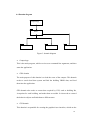
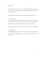
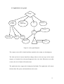
Australian National University
Comp 6703 eScience Project
Semester 1,
2005
Visit ANU Campus in the Wedge(VACIW)
Student: Feng SHEN
Id: u3390679
Supervisor: Pascal Vuylsteker
1
1.
Introduction............................................................................................................................3
1.1 Project Scope......................................................................................................................3
1.2 Project Management .........................................................................................................3
2.
Overall Description................................................................................................................4
2.1 Product perspective ...........................................................................................................4
2.2 High level functions ...........................................................................................................5
3.
Specific requirements ............................................................................................................6
3.1 Event and action list ..........................................................................................................6
3.2 Detail requirements ...........................................................................................................9
4.
Design Description ...............................................................................................................11
4.1 Design method .................................................................................................................11
4.2 Data description...............................................................................................................11
4.3 GUI design .......................................................................................................................13
4.4 Domain diagram ..............................................................................................................14
4.5 Application scene graph..................................................................................................16
4.6 Class diagram ..................................................................................................................17
4.7 Class description..............................................................................................................17
5.
Software implementation ....................................................................................................19
5.1 Menu structure (SubMenu.java & MenuItem.java) ....................................................19
5.2 Exploring Menus (Menu3D.java & SubMenu.java) ....................................................21
5.3 Dynamic menu items (Menu3D.java) ............................................................................22
5.4 Intent visit buildings ( Menu3D.java )...........................................................................23
5.5 Viewpoint (BuildingDataSet.java & Campus.java)......................................................23
5.6 Internal database (Campus.java)...................................................................................24
5.7 BuildingSearcher (BuildingSearcher.java)....................................................................25
5.8 Viewpoint switch..............................................................................................................25
5.9 Smooth transition (Campus.java) ..................................................................................25
5.10
Tour animation............................................................................................................27
5.11
Walk controller (WalkController.java) .....................................................................27
5.12
Examine controller (ExamineController.java) .........................................................29
5.13
Status (KeyState.java).................................................................................................30
6.
Software testing....................................................................................................................30
6.1 Unit test ............................................................................................................................31
6.2 System test........................................................................................................................31
7.
User documentation .............................................................................................................33
7.1 System Configuration......................................................................................................33
7.2 User manual .....................................................................................................................35
8.
Project comments.................................................................................................................37
8.1 Problems...........................................................................................................................37
8.2 Future work .....................................................................................................................38
9.
Acknowledgement ................................................................................................................39
2
1. Introduction
1.1 Project Scope
From the wedge, a user should be able to use some application to explore the
virtual ANU campus. He is able to see the roads, buildings, bridges, trees and
other places of the campus. Without having a real visit, he can have a generic idea
of what the camps looks like. This application is called visit ANU campus in the
wedge (VACIW).
A project called Campus3D is implementing by Mr. Enlai Yi at this semester and
will export some data which models the 3d campus in VRML format.
The scope of the application is to load the VRML campus data from local file
system, render it and display to the user in the wedge. Through the functions
provided by the software, users shall be able to explore the virtual campus.
1.2 Project Management
Timetable
Week
Dates
Notes
1
21-27 Feb
Chose a supervisor/client/subject and Get started!
2-4
28Feb – 20March
Details of requirements
5-6
21 – 3 April
Modeling and Learning of Chosen Technics Phase
7-8
4 - 17 April
Implementation
9
18 - 24 April
Mid-project result (prototype, report draft, first implementation ...) due
10
25 - 1 May
Comments by supervisors
11
2 - 8 May
Implementation of Comments
12-13
9 - 22 May
Debugging & Documentation
3
Week
Dates
Notes
14-15
23May - 5June
Implementation completed
16
6 - 12 June
Project presentation (*).
17-18
20 - 24 June
Final Reports due at 4:00 pm on Friday, 24nd of June (*).
A timetable is well defined at the starting phase of the project, and the timetable
will be used to manage and control the project development process.
2. Overall Description
2.1 Product perspective
2.1.1
Context diagram
WEDGE
Virtual campus
Menu items
VACIW
User operation
Request
for data
Data
Selection of
operation
Domino
Local File
System
Figure1: context diagram
4
2.1.2
User interface
The menus will be the main interface for user to interact with the VACIW. The
available operations at specific stage for exploring the virtual campus will be
provided through the menus. Users are able to display or hide menus at any
time.
The domino or keyboard will be used as the input devices for this application.
Users can use either of the devices to interact with the wedge system.
A pair of special 3d glasses will be fitted, and user shall be able to use such
glasses to view the virtual 3d campus.
Head tracker and 3d mouse may not be implemented in the initial version. In
the future versions, these two devices could be implemented to provide user a
more realistic virtual experience.
2.1.3
Software interface
The application shall load the virtual campus data from the local file system.
An appropriate loader would be the interface between the application and
VRML data.
The TIWI package is the interface between the application and wedge system.
TIWI is the platform developed by eScience department for creating wedge
applications.
2.2 High level functions
2.2.1
Load existing virtual campus data, and display it to the user. The
starting scene shall be the campus street map, from the top view.
2.2.2
User can locate a building from the campus street map, and look at the
5
building at pre-defined viewpoints.
2.2.3
User shall be able to walk around in the virtual campus, using the
domino or keyboard. User shall be able to move ahead/back, move
left/right, look up/down, and turn left/right. The scene displayed to the
user through the wedge shall be nature, and similar to the real
environment. Furthermore, user shall be able to examine a target
building in the virtual campus.
3. Specific requirements
3.1 Event and action list
Event
Action
Condition
User starts the
Map of campus displayed to
Campus data in vrml
application.
the user from the top view.
file available.
Events for 2.2.1
Menu will be displayed.
Help info will be available.
User inputs intent-visit
Intent visited building
The building data is in
buildings through
available on the relevant menu
the vrml file system.
command line when
items.
starting application.
User selects Exit Menu
The application should exit.
None.
The menu should be displayed
At any time, when user
or hidden, depending on if
is in control of the
menu is displayed.
application.
item or press key “Q”.
User press key “Esc”.
6
User presses the space
Current menu item is selected.
Application is on the
key.
If current item has submenu,
menu status.
then submenu is displayed.
User press up/down/left
Different levels of submenus
Application is on the
/right arrow keys.
should be displayed to user.
menu status.
User can also use right arrow
key to select a menu item.
User select Help menu.
Help information shall be
Help information not
displayed to user. The
displayed.
information will include key
functions and other user guide.
User select Help menu
Help information shall be
Help information is
again.
hidden.
displayed.
User selects a building
The menu will be hidden. This
None.
through levels of
building displays, from the
submenu.
pre-defined viewpoint.
User selects another
User will be transformed to
building.
this selected building, in a
Events for 2.2.2
None.
smooth transition way.
User select Building
Pre-defined viewpoints for
Viewpoints are
Viewpoint menu.
selected building are available
pre-defined in the
as menu items.
building vrml file.
User select a building
The viewing camera is
Viewpoints available.
viewpoint
switched to the selected
viewpoint. This will be a
smooth transition.
User select another
The viewing camera is
Campus viewpoint
7
campus viewpoint
switched to the selected
available.
viewpoint.
Events for 2.2.3
User press left/right
User moves to the left/right.
Application in the
arrow key
This is Doom-like behavior,
walk mode.
and the viewing camera moves
to the left/right. The
orientation doesn’t change.
User press up/down
User moves ahead/back. This
Application in the
arrow key.
is Doom-like behavior, and
walk mode.
user feels like walk
ahead/back.
User press page up/down
This is like user looks
Application in walk
keys.
up/down.
mode.
User press L/R keys.
User feels like turns left/right.
Application in walk
The viewing camera is rotated
mode.
to the left/right.
User select Examine
The application mode should
None.
mode.
be changed to examine mode.
User press left/right
The user shall be able to rotate
Application in examine
arrow key.
the selected building to
mode.
examine it. The center of such
kind of rotation will be the
center of target building.
User select tour mode
The define tour will guild user
Tour mode.
around the campus. This is an
animation.
8
3.2 Detail requirements
3.2.1
User shall be able to load the existing data on the local file system. The
data is not the VACIW application itself, but it needs to be installed in
the local disk drive. The default folder “wedge” is assumed to hold the
local file system. The campus will be modeled in vrml language and
the data will be stored locally.
3.2.2
A campus street map shall be displayed to the user, when the
application is launched. User shall be at the top view, and have a top
view of the campus.
3.2.3
User shall be able to exit the application at any time. An exit menu
item should be provided to user, and it shall be easy to access on the
screen. When the application terminates, all the campus data shall be
remained and not modified.
3.2.4
A menu system should be provided to user. User can explore the
different levels of menu items, and make selection. The arrow keys
shall be used to explore the menu, space key shall be used to make
selection.
3.2.5
Help information should be provided to user. The help information
shall include keys functions description. Help information shall be able
to hide/display.
3.2.6
User shall be able to view a building. He can choose the ID of a
specific building, and the system shall display the 3d scene at the
default viewpoint.
3.2.7
The available building IDs in the menu should be created dynamically
9
from the data of local data system. If local data system has the data for
a specific building, then the building ID shall be accessible through the
menu.
3.2.8
The available building viewpoints shall be the viewpoints for currently
selected building. When user selects another building, the available
viewpoints shall be updated.
3.2.9
User shall be able to switch between different viewpoints, and the
transition between viewpoints should be smooth, not directly or sudden
switching.
3.2.10 User shall be able to switch between different application modes,
through menu items. The different modes should be easy to access at
any time.
3.2.11 User shall be able to walk around in the virtual campus. User shall be
able to move to the left/right, and walk ahead/back.
3.2.12 User shall be able to turn left/right.
3.2.13 User shall be able to look up/down.
3.2.14 User shall be able to examine a building. When a building is selected,
user shall be able to rotate the building using the domino or keyboard.
3.2.15 The application shall provide some animation tour, to guide user flying
around the campus.
10
4. Design Description
4.1 Design method
The design will be traditional design. This includes requirements modeling,
software design, software implementation and software test.
4.2 Data description
The data information of the system will be modeled to comply with GIS(Global
Information System) standard.
In this project, the campus will be modeled in VRML language and the data for
each building will be modeled as GIS system and grouped into different level of
details.
Here is the definition of GIS level of details, used by the input VRML data:
LOD0 ---- The basic information of a building including the ID, name, description,
location, shape and etc. Normally they are stored in a single .html file. The system
will output this HTML file according building information, and other higher level
VRML model will anchor a link to such HTML file.
LOD1 ---- In this level, we use a bounding box to denote the building (the shape
for this bounding box usually is a rectangle). In the VRML model, we will use a
billboard with a texture to denote this bounding box. The character for the
billboard is that the content always faces the user and rotates around a specified
axis.
LOD2 ---- In this level, we can use more detail shape to denote the building in a
simple VRML 3D model, the shape includes rectangle, cycle and polygon, and for
11
each side user can add different texture.
LOD3 --- At this level, user can save and input external high level of detail VRML
3D model to the Campus3D system and can save more pictures about the outside
of building.
LOD4 --- Including LOD3 data and the pictures about the inside of building.
The higher the level of detail is, the more realistic the 3D model for the buildings
and the 3D scene for the campus will be. With such 3D model data, the user can
easily form the understanding of the terrain of the campus. The levels of detail
that contains 3D models can also be placed into a single 3D model scene. In this
way, different distance between the view point and the 3D scene will lead to
different 3D models displayed in the 3D space.
The application itself will not include any such data. However, some demo VRML
data will be used to test and demonstrate the application.
12
4.3 GUI design
Building 1—30
Building 31—60
Building 61—90
Building 91—120
Building 121--150
WALK
Intent Visit
Campus Viewpoint
Building Viewpoint
Tour
Examine
Help
Exit
Building 1—5
Building 6--10
Building 11—15
Building 16—20
Building 21—25
Building 26—30
Building 50
Buiding 120
Building 2
Building 5
Top view 1
Side view2
N to S
East to West
Figure2: menu system diagram
Bold box – dynamic menu items, which changes depending on the application status.
Normal box – static menu items, which doesn’t change.
Menu is the main user interface. User should be able to use keyboard or domino to
explore the menu items, and access the functions provided by the application.
Menu items of bold box in figure2 are dynamic. The application reads the data
information from the local file system, extracts the relevant data and then generates
the menu items. The items depend on the current status of application and the target
building.
13
4.4 Domain diagram
CampusApp
GEO
GUI
BEHAVIOR
VRML
Figure 3: domain diagram
•
CampusApp
This is the main program, which receives user command line arguments, and then
starts the application.
•
GEO domain
The main purpose of this domain is to load the scene of the campus. This domain
needs to search local data system and find the building VRML data, and load
them into the application.
GEO domain also needs to extract data required by GUI, such as building Ids,
viewpoints for each building, and make them accessible. It also needs to created
the behavior objects and bind them to different state.
•
GUI domain
This domain is responsible for creating the graphical user interface, which are the
14
menu items.
GUI domain needs to request data from GEO domain, dynamically generates
some menu items. When the current status of application changes, the menu items
need to be updated.
GUI domain needs to bind the functions of the application to the menu items.
•
Behavior domain
This domain needs to deal with application behaviors which correspond with the
user input. When it receives user input, it needs to get the current status of the
application, and then decides which behavior needs to responds to the input.
Each status will have a corresponding behavior object to deal with the key inputs.
•
VRML domain
This domain is the data system, and they are assumed to be provided and installed
locally. The data format shall meet the specification of application data
requirements.
15
4.5 Application scene graph
Wedge
Loaded
SCENE
BACK
GROUND
BG
LIGHT
CarpetTG
TG
Building
Bud
Bud
MENU
VP
VIEW
Figure 4: scene graph diagram
The campus scene will be loaded and then attached to the wedge as a branchgroup.
The look and size of menus should not change wherever the user stays in the virtual
campus, so I attached it to the transformgroup in the view side. When the user walks
or turns, the size of menu will remain same.
The application does support the background and light. The application will extract
the data from file system, and attach them to the scene.
16
4.6 Class diagram
GroundPlane
BuildingSearcher
ObjectScene
Campus
BuildingDataSet
MenuItem
Menu3D
SubMenu
KeyState
MenuController
WalkController
ExamineController
Figure 5: class diagram
4.7 Class description
•
ObjectScene, class for loading an object from a VRML file. The Xj3D loader
will be used to load the scene. Then the scene could be returned as a
17
BranchGroup object, and other properties of the scene like viewpoints, light
nodes, named objects and so on will be returned.
•
BuildingSearcher, class for searching local data directory “wedge”, find all
the available building IDs. Then a linkedlist of these building IDs will be
returned. This list will be used to check against user intent visit buildings, see
if the intent visit buildings are available.
•
Campus, class for combining all things together. This class will use several of
other classes to add buildings, menus, behaviors, to extract and maintain an
internal database, which is the dataset of all available building data.
•
GroundPlane, class for creating green ground which is surrounding the
campus map.
•
MenuItem, class for defining a single item, and this is also a super class for
subMenu.
•
SubMenu, class for defining a sub menu, which may have multiple
menuitems and submenus as children.
•
Menu3D, class for creating the whole menus, combines submenus and
menuitems together. The menu will have some static menu items which are
created when this Menu3D object is created, and some dynamic menu items
which are created at run time, based on the different application status.
•
KeyState, class for modeling application status. The status includes menu
state, walk state, examine state and tour state. Keys will be binded with
different behaviors depending on the status.
18
•
MenuController, creates behaviors when application is at menu state. The
behaviors are created for user to explore different levels of menu, to select a
specific menu item, and then activate the function for that item.
•
WalkController, creates behaviors when application is at walk mode. When
this mode is in active, the keys are binded for the purpose of moving around
within the campus. Eg, arrow up key may used to move ahead.
•
ExamineController, creates behaviors when application is at examine mode.
When this mode is in active, keys are binded for the purpose of examine a
specific object. Eg, arrow up key may be used to push a building far away.
5. Software implementation
This part will describe some important algorithms involved and implementing
issues.
5.1 Menu structure (SubMenu.java & MenuItem.java)
As seen in the class diagram, SubMenu class is inherited from MenuItem.
MenuItem defines a single item and SubMenu contains some SubMenu and
MenuItems.
19
Parent
SubMenu
Switch
Label1
Label2
Sub1
Sub2
Item3
Label3
Figure 6: Menu scene graph diagram
A submenu itself is a branchgroup, has a parent and contains sub1, sub2, item3 all
as branchgroup. It also has a switch which has Label1, label2, label3 also as
branchgroup, where labels are 3d text display for sub1, sub2 and item3. Here sub1
and sub2 have same structure as subMenu.
When this subMenu is selected, then the switch will be set to all, while all sub1,
sub2 and item3 will disable. Then menu items of this submenu will be displayed.
If sub1 is selected, then the switch for the subMenu will be set to none, and the
switch of sub1 will be set to all. Then menu items of sub1 will be displayed, and
items of submenu will be disabled.
20
5.2 Exploring Menus (Menu3D.java & SubMenu.java)
In Menu3D, a private variable called “current” is used to keep the current
SubMenu object. The root menu is a SubMenu with null parent, so at start-up,
current references to root menu.
Each SubMenu object contains a variable highlighted_item_num, which means
which item is selected currently.
Therefore, current keeps submenu information, highlighted_item_num which item
is selected keeps in this submenu. So current menu item at any time is determined
by the both variables.
Methods for SubMenu.java:
Method up: When a user uses arrow up key to goes up, application just makes
variable highlighted_item_num +1.
Method down: If goes down, just highlighted_item_num –1.
Methods for Menu3D.java:
Method left: When a user uses arrow left key to goes to parent menu, just sets
current to the parent SubMenu.
Method right: sets current to highlighted_item_num item if it is a submenu,
otherwise select this menuitem.
Furthermore, the root menu is placed into the 3d scene graph as a branchgroup.
Regardless of wherever the user stays in the virtual 3d world, the display of menu
21
should be identical, and distance between user and menu should same all the time.
Thus, I set the menu as viewpingplatform geometry. Then user should be able to
see the same menu wherever he/she stays.
5.3 Dynamic menu items (Menu3D.java)
Some menu items needs to be created at run time, such as available buildings, and
available viewpoints for a specific building.
When implementing the program, available buildings are unknown and only
known after the software processes the data. For the “available viewpoints” menu
item, when another building is selected, all viewpoint items need to be updated.
Here in my implementation, only menu items are dynamic, and submenus are
static. All submenus which will contain those dynamic items are created at
start-up, and then placed into menu system.
After processing the data, available buildings will be categorized into appropriated
submenu. Most building id will be an integer, eg building 107, then it will be
compared with the building range and place into submenu building 106-110.
For
those building Id ended with A or B, like building 107B, then the comparison
algorithm would be a bit different. B will subtract from the string first, and then
make the comparison.
For those building id with text, I put them into another group called Building with
text ID.
For the available viewpoints. When another building is selected, previous
viewpoints will be cleaned. Then based on selected building id, application will
search through internal building database (details will be discussed later), and get
22
all matched viewpoints, generating viewpoint menu items.
5.4 Intent visit buildings ( Menu3D.java )
User may launch the software with some specific buildings he/she wishes to see.
These command line arguments will then be processed and thus the related
options will be provided as menu items.
Before those menu items could be displayed, application needs to check if these
buildings are available by the input data.
Method: addPreVisitItems
This method gets the building argument list, then compare with the list of
available building list. Only menu items of matched buildings will be created.
5.5 Viewpoint (BuildingDataSet.java & Campus.java)
From the pre-analysis of the input data, the viewpoint information of a specific
building is separated into two parts, one is the transformgroup of this building,
and the other is the tranformgroup of viewpoint relative to the building. Therefore,
the viewpoint information is locally, and can not be applied into the whole scene
directly.
The viewpoints provided by the Xj3D loader which loads the input campus data
are simply the relative viewpoints. Thus we need to process and get the absolute
transform group of the viewpoints. The solution is to multiply Transform3D of
building and Transform3D of viewpoints.
In Campus.java, I try to get the Transform3D of a specific building when I use
23
ObjectScene to load the campus data scene.wrl. Since every building
TransformGroup in VRML file has a unique name TM_Building_id, eg
TM_Building_107, I use interface getNamedObject to get the transform3d of this
building.
Then in BuildingDataSet.java, I directly load file “wedge/107/107.wrl”, and get
all the local viewpoints. Here I didn’t use loader in Campus.java to get viewpoints,
because where the viewpoint I got are all viewpoints mixed together, without
information of which viewpoints belong to which building.
Lastly, I multiply the transform3d of building and transform3d of viewpoint. If it
happens that there is no defined viewpoint for a building, I will append a default
viewpoint for that building, for easy access to the building.
5.6 Internal database (Campus.java)
An internal database of input data is maintained after data is loaded and processed
by the application. The database is simply a list of BuildingDataSet, each of which
is the data for a specific building, including buildingId, building tranform3d, and
all available viewpoints.
The database is created when the application is launched. In Campus.java, the
algorithm for creating such database is like this:
use BuildingSearcher ojbect to get a list of all avaliable buidlings
get all named objects from loaded scene as a hashtable
for each building
find the matched transformgroup in hashtable base on id
get the transform3d from this transformgroup
24
create a BuildingDataSet object(id, transformgroup)
add this BuildingDataSet into a list
5.7 BuildingSearcher (BuildingSearcher.java)
This is used to search local data file systems, to find the available buildings, and
then return a list of building ids.
Here we assume that for every building, a directory named as building id will be
used to hold all the data information. Eg, if we have building 107, there must be a
directory 107 existing under wedge directory. So here I search through all
directories under wedge, and I will have all the available buildings.
5.8 Viewpoint switch
When user is exploring the virtual campus, and selects a specific building, then
user’s view needs to be transferred to that building. This could be interpreted as
switch the current viewpoint to the viewpoint of that building
Here I simply set the targetTG which represents the user’s view to the target
viewpoint. While sudden transition will involved, and may make user confusing, a
more nature way called smooth transition will be employed to improve such
viewpoint switching.
5.9 Smooth transition (Campus.java)
Smooth transition is defined as smoothly translate view(targetTG) from current
viewpoint to a target viewpoint.
To provide user with a more nature virtual experience, smooth transition between
25
viewpoints becomes a fundamental requirement.
To achieve this function, the RotPosPathInterpolator is used. Algorithm is like
this:
Define an alpha
Set start-time to current time
Create AxisAngle4f object as identity
Define two knots, 0 for current viewpoint and 1 for target.
Get Matrix4d from current targetTG, and set as quats[0]
Get position(x,y,z) from current targetTG and set as position[0]
Get Matrix4d from target viewpoint, and set as quats[1]
Get position(x,y,z) from target viewpoint and set as position[1]
Create RotPosPathInterpolator object with above information and
targetTG, and attach it to the wedge
Then the targetTG will be smoothly translated to the target viewpoint.
But this also introduces a small problem. When user is successfully switched to
the target viewpoint, if he/she wants to move around, he/she will be brought back
to the starting viewpoint. This is because the Transform3D of targetTG in the
behavior object is not updated. When user uses the behavior object to move
around, the old version of transform3D applies.
To solve this problem, the tranform3D in behavior object needs to be updated.
But you can not update this directly after the smooth transition procedure, because
the Interpolator creates another thread to execute the animation, the update will be
executed before animation finishes. Therefore the displayed frames would be like
26
this, current viewpoint first, then suddenly target viewpoint, while animation
running at the same time. Lastly continue and finish the animation. Frames will be
overlapped.
In the implementation, I put the update method into the behavior object, for the
key strokes after the animation finishes. Then the tranform3D will be updated
before any user input behavior.
5.10 Tour animation
The tour is defined as an animation which guides the user around some specific
places. In the implementation, I just developed some demo tour, without any
interface provided for user to define such kind of tour.
The tour algorithm is similar to that of smooth transition. For demo tour E-W, I
defined 4 knots, current viewpoint, a viewpoint in the east of campus, a viewpoint
in the west and last back to the starting viewpoint. The other demo tour N-S is
similar.
5.11 Walk controller (WalkController.java)
The algorithm for walk behavior is from the Computer Graphics tutorial from
Pascal Vuylsteker.
The algorithm is like this:
For movement:
Define t3dVals as Matrix4d, then:
viewT3D.get(t3dVals);
27
double xpos = t3dVals.getElement(0,3);
double ypos = t3dVals.getElement(1,3);
double zpos = t3dVals.getElement(2,3);
double ix = t3dVals.getElement(0,0);
double iy = t3dVals.getElement(1,0);
double iz = t3dVals.getElement(2,0);
double jx = t3dVals.getElement(0,1);
double jy = t3dVals.getElement(1,1);
double jz = t3dVals.getElement(2,1);
double kx = t3dVals.getElement(0,2);
double ky = t3dVals.getElement(1,2);
double kz = t3dVals.getElement(2,2);
xpos += dx*ix + dy*jx + dz*kx;
ypos += dx*iy + dy*jy + dz*ky;
zpos += dx*iz + dy*jz + dz*kz;
t3dVals.setElement(0,3,xpos);
t3dVals.setElement(1,3,ypos);
t3dVals.setElement(2,3,zpos);
viewT3D.set(t3dVals);
For yaw an angle:
rotateT3D.rotY(da);
viewT3D.mul(rotateT3D);
28
For pitch up/down:
rotateT3D.rotX(da);
viewT3D.mul(rotateT3D);
5.12 Examine controller (ExamineController.java)
B
r
A
Figure 7 Examine algorithm
In the Java3D application, OrbitBehavior suppose to provide such kind of
operation with mouse. But actually in first version of this application, 3d mouse is
not implemented. Thus, such kind of behavior needs to be implemented manually.
In figure 6, suppose the black point is the center of a building, and a user wants to
rotate the building to the left. This is same as the user move to the right of the
building.
Here suppose user moves from A to B, along the circle original at the center with
radius r. I mathematically calculate the position of B, and then rotate back an
angle from A to B.
The math formulas are:
x_b = x_c + (x_a – x_c) * cos(angle) - (y_a – y_c) * sin(angle)
y_b = y_c + (y_a – y_c) * sin(angle) + (y_a – y_c) * cos(angle)
Where b is for position B, A for position A, c for center, and angle is the angle
from A to B.
29
5.13 Status (KeyState.java)
Walk
Menu
Examine
Figure 8 : Finite state diagram
In the application, the states are defined as finite state. The application has walk,
menu, examine and tour state. For different states, the input keys are binded for
different purpose.
As tour state is an animation, which is being executed without any key input, and
return to previous state when the animation is finished. So the tour state is ignored,
and only the above three are modeled.
KeyState is used to model the application state. The application is started as menu
state, and then goes to different states. The walk state can not go to examine
directly, and needs to go through menu, then examine.
At state of walk or examine, ESC key could call back the 3d menu, thus changes
to menu state. One more ESC will hide the menu and go back to the previous
state.
6. Software testing
As this project is developed by one person, only unit test and system test are
executed.
30
6.1 Unit test
Unit is the test of the single unit of code. The unit could be a single method,
function or a class.
This kind of test is done together with the application implementation.
6.2 System test
System test is that all software application, external package and hardware being
tested together.
•
Platform: pc with windows/linux
The software application is tested on different platform, home pc with windows,
lab pc with linux, and the wedge system.
The software could be run at both windows and linux platform. I did both batch
and make file for compile and run the application. And the scenes presented to the
user are identical.
31
Figure9: Shot of the scene
This is the screen shot of scene running at windows platform. It is a top view of
the campus. The software is implemented with two screens as default; it works
well with the pc with one screen monitor. All the behaviors of walk, menu,
examine and tour work well on both platforms.
•
Wedge with one/two screens
This software is also tested on the wedge. The wedge is configured with two
screens, and the scene will be divided into the two screens when the application is
launched in the wedge.
Because one screen of wedge is temporally not working, so the application is
modified to run on one screen. This introduces a minor problem, that at the startup
the color of menus becomes yellow, not red with green for highlighting as
designed. Then it makes user confusing because user is not able to distinguish
32
which item is highlighted. After user takes some behavior operation, eg select a
specific building, and then color becomes normal. Problem only appear at the top
view. This is a strange problem, as the color is ok with two screens, but has
problem with one screen.
All behaviors work well on the wedge with both one and two screens.
•
Input data
The software suppose to import the vrml file from project Campus3D carried by
Mr. Enlai Yi, so I tested two version of input VRML data as the test stage. One
version of such data is integrated into the software package as demo data, and the
other version is the data with fewer buildings.
Both versions work well with the software.
•
User interaction
Interaction includes user interact with application using domino/keyboards, thus
executing a series of behaviors for some user scenarios.
During all above tests, all functions provided by the application are easier for user
to access using the keyboard. All the behaviors defined in the software
requirements are covered, and some user specified scenarios were also tested. All
behaviors are implemented complying with the software requirements.
7. User documentation
7.1 System Configuration
33
•
Configuration:
The software and other deliverables are packaged into “project” directory. The
project directory contains 5 parts, “anu” directory is the input VRML data,
“extPackage” directory is the external package used by xj3d loader, “tiwi”
directory is the wedge platform package, “Campus” is the actual application of
this project, and “doc” directory is the javadoc API.
Exact the jar file into a disk drive.
The assumed structure is that "extPackage", "tiwi", "campus" and "anu" are in the
same directory, because the batch file contains the assumed class path. Then the
build and run batch can be used directly.
If structure is modified, you need to explicitly specify the class path for
extPackage and tiwi.
•
Compile/run
Build:
Execute build.BAT
Or “make clear” then “make build” in linux
or goes to Campus directory, setup classpath
then run: javac CampusApp.java
Run:
Execute run.BAT
or “make run” in linux
34
or goes to Campus directory
then run: java CampusApp uni_data_path intent_visit_building_list
eg:
java CampusApp ../anu 105 12 5 csit
Here the uni_data_path and intent_visit_building_list could be changed.
Clear:
Execute Clear.BAT or make clear
7.2 User manual
•
user guide
When the application is launched, the scene will be presented to the user from a
top view, with a 3D menu on the left. The menu items are in red color, and the
highlighted item is in green color.
All the interactions are through the menu system. The menu systems are similar to
the normal application menus, and the operations of menu are same as other menu
system.
Simple description of main menu:
Walk Mode – to locate a specific building
Intent Visit – the buildings user intent to visit
Top view – the top view of campus scene
Building Viewpoints – available viewpoints for the target building
Tour Mode – an animation tour of campus
Examine Mode – examine a target building
35
Help – simple description for keys
Quit – quit the application
Before user starts to carry walk or examine behavior, he/she needs to locate an
available building as the target. Then user should be able to walk around use keys
defined bellow.
Any change of viewpoint, building or mode should go through menus. User can
press Esc key to display/hide the menu, and carry the intended operation.
•
Key functions
Based on the different application state, the keys are binded for different purpose.
For all mode:
Esc key for display/hide menus.
Space key for selecting.
Q key for quit the application.
For menu mode:
← → key for move to parent/child menu.
If current menu doesn’t have a child, →will select current item.
↑ ↓ key for moving up/down highlighted item.
For walk mode:
← → key for moving left/right.
↑ ↓ key for moving ahead/back.
W, S key for pitch up/down.
A, D key for yaw left/right.
Page up/down for pitch up/down.
36
For examine mode:
← → key for rotate target building left/right.
↑ ↓ key for push away/pull close the target building.
W, S key for moving view up/down.
Page up/down for moving view up/down.
•
Domino configuration
Domino configuration is not component of the software application itself. Domino
can be setup through the domino control panel, which could be found in the
control panel of OS in the wedge. Every key on the domino can be mapped to a
specific key of keyboard. Then the key of domino can function as key of
keyboard.
8. Project comments
8.1 Problems
•
Loader problem
A powerful loader is critical for this application, because all features of VRML
data need to be loaded and displayed. Texture and billboard could give user a
better presentation of the 3d campus, and LOD behaviors may save a lot of
computing resource.
In the implementation I tried with two loader J3d-vrml97 and Xj3D loader.
J3d_vrml97 does support the texture and LOD behavior. The LOD behavior
automatically applies when the scene is loaded, and you don’t have to manually
configure such behavior in Java3D. But this loader has bad error tolerance and the
application will get a lot of strange exceptions and exit.
37
Current Xj3D loader is currently at milestone version 10, and is not a formal
release. It doesn’t flexibly support texture. For the campus map, which is a texture,
the loader works well, but it doesn’t support the texture of building in input data.
It’s because the texture of map is mapping to 4 points while building texture is
mapping to an extrusion of a line. It also doesn’t support LOD well.
I have sent the demo code and vrml file to one of the sun Xj3D maintainer. Hope
in the next release of this loader, they will fix the problem.
•
Color problem
I found this problem in the test stage. The problem is color of menus at the top
view of the campus. The designed color is red with green for highlighted item. It
works well when using two screens in the wedge, but doesn’t work well when
using one screen. Both colors become yellow, and make user very difficult to
distinguish which one is highlighted. While at other views than top view, it works
well.
I have talked this to James, since the menus are modification of his code. But
neither of us has got the reason.
8.2 Future work
•
Loader
Loader problem needs to be solved in the future version of this application, as
textures can give user a much better campus scene. Probably change the mapping
format of buildings to mapping format of campus map will make the texture work.
But the billboard and LOD still needs to be solved.
•
GIS details
The VRML data is defined to comply with GIS standard. This wedge application
38
shall be able to access more details of the campus, therefore, provides a more real
and nature virtual world to the user.
•
User defined tour
The tour is an interesting feature of this application. The future version can
provide function for user to define the tour route, places, and speed and so on. For
a user first time plays with the virtual campus, the tour will make him/her much
easier to explore the virtual world.
•
Smooth transition
Currently the transition between two viewpoints is defined through two knots,
and thus may goes through some buildings. A more realistic way to implement
such transition is to define a third knot, which makes the transition not go through
any buildings. The knot could be some where above the building, or somewhere
computed in the space between buildings.
•
Usability
Usability is an important feature for a well designed software application. For
example, the color problem I mentioned previously will bring usability problems.
And some of the menus and user interaction may not be well designed. A usability
study could be carried and thus improve the usability of this software.
9. Acknowledgement
I would like to thank the following people:
Pascal Vuylsteker, my supervisor.
James Sheridan, for help with menu code and configuration of wedge.
39