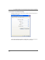
1
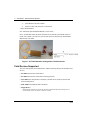
SMARTLINE
CONFIGURATION TOOLKIT
SCT 3000
Installation and Start-Up Guide
Doc No.: 34-ST-10-08
Release Date:
6/12/08
SCT 3000 Smartline Configuration Toolkit
Notices and Trademarks
Copyright 2008 by Honeywell Inc.
May 15, 2008
While this information is presented in good faith and believed to be accurate, Honeywell disclaims
the implied warranties of merchantability and fitness for a particular purpose and makes no
express warranties except as may be stated in its written agreement with and for its customers.
In no event is Honeywell liable to anyone for any indirect, special or consequential damages. The
information and specifications in this document are subject to change without notice.
Honeywell is a U.S. registered trademark.
Other brand or product names are trademarks of their respective owners.
Honeywell Inc.
Honeywell Process Solutions
2820 West Kelton Lane
Phoenix, AZ 85053-3028
1-800 852-3211
ii
SCT 3000 Installation and Start-Up Guide
Release 6
06/08
SCT 3000 Smartline Configuration Toolkit
About This Document
Revision Notes
The following list provides notes concerning all revisions of this document.
Doc ID
34-ST-10-08
Rel ID
E
Date
05/08
Notes
Redesign the SCT 3000 software to replace the
PCMCIA Interface with the Honeywell’s DE /
HART Modem
34-ST-10-08
D
03/00
Serial interface capability and STT150 support.
34-ST-10-08
C
12/98
Release 200. Flow Compensation Wizard.
References
The following list identifies all documents that may be sources of reference for material discussed
in this publication.
Document Title
SMV 3000 Smart Multivariable Transmitter
User’s Manual
Doc ID
34-SM-25-02
ST 3000 Smart Transmitter Release 300
User’s Manual
34-ST-25-14
STT 3000 Version 350 User’s Manual
34-ST-25-12
STT 3000 Series STT250 Operator Manual
EN1I-6190
STT 3000 Series STT150 Operator Manual
EN1I-6248
MagneW 3000 Electromagnetic Flowmeter
User’s Manual
36-KI-25-01
MagneW 3000 PLUS Electromagnetic
Flowmeter
36-KI-25-02
Release 6
06/08
SCT 3000 Installation and Start-Up Guide
iii
SCT 3000 Smartline Configuration Toolkit
Contacts
World Wide Web
The following lists Honeywell’s World Wide Web sites that will be of interest to our industrial
automation and control customers.
Honeywell Organization
Corporate
WWW Address (URL)
http://www.honeywell.com
Honeywell Process Solutions
http://hpsweb.com
International
http://www.honeywell.com/Business/global.asp
Telephone
Contact us by telephone at the numbers listed below.
Organization
iv
Phone Number
United States
and Canada
Honeywell Inc.
Industrial Automation and Control
1-800-343-0228
1-800-525-7439
Asia Pacific
Honeywell Asia Pacific Inc.
Hong Kong
(852) 8298298
Europe
Honeywell PACE
Brussels, Belgium
[32-2] 728-2111
Latin America
Honeywell Inc.
Sunrise, Florida U.S.A.
(305) 364-2355
SCT 3000 Installation and Start-Up Guide
Sales
Service
Release 6
06/08
SCT 3000 Smartline Configuration Toolkit
Symbol definitions
The following table lists those symbols used in this document to denote certain
conditions.
Symbol
Definition
This CAUTION symbol on the equipment refers the user to the
Product Manual for additional information. This symbol appears next
to required information in the manual.
This WARNING symbol on the equipment refers the user to the
Product Manual for additional information. This symbol appears next
to required information in the manual.
WARNING: risk of electrical shock. This symbol warns the user of a
potential shock hazard where HAZARDOUS LIVE voltages greater
than 30 Vrms, 42.4 Vpeak, or 60 VDC may be accessible.
ATTENTION, Electrostatic Discharge (ESD) hazards. Observe
precautions for handling electrostatic sensitive devices
Release 6
06/08
SCT 3000 Installation and Start-Up Guide
v
SCT 3000 Smartline Configuration Toolkit
Contents
1— Introduction....................................................................................... 1
Smartline Configuration Toolkit ....................................................................................1
Field Devices Supported ..............................................................................................2
SCT 3000 Features ......................................................................................................3
2— System Requirements ...................................................................... 5
Before You Begin .........................................................................................................5
Computer Requirements ..............................................................................................5
Software Compatibility..................................................................................................7
SCT Hardware ..............................................................................................................8
3— Software Installation ....................................................................... 11
SCT 3000 Installation .................................................................................................11
SCT 3000 Software Application and Setup ................................................................11
CD ROM Installation...................................................................................................12
4— Hardware Installation...................................................................... 13
SCT Hardware ............................................................................................................13
DE / HART Modem.....................................................................................................13
DE / HART Modem hardware assembly and installation ...........................................14
Serial Hardware Interface (for use with STT 150 only) ..............................................17
5— Start up and Working Online........................................................... 21
SCT 3000 Application.................................................................................................21
Getting Online Quickly................................................................................................21
SCT 3000 Features ....................................................................................................28
6— Working Offline ............................................................................... 31
Using the SCT 3000 Offline........................................................................................31
7— Online Help..................................................................................... 35
Online Help Features..................................................................................................35
vi
SCT 3000 Installation and Start-Up Guide
Release 6
06/08
SCT 3000 Smartline Configuration Toolkit
8— Troubleshooting ..............................................................................37
Overview .................................................................................................................... 37
Troubleshooting SCT Application and the hardware ................................................. 38
Troubleshooting SCT 3000 Operation ....................................................................... 38
SCT Error Codes........................................................................................................ 42
Status Bar .................................................................................................................. 45
Modem Maintenance ................................................................................................. 47
Honeywell’s Technical Assistance Center ................................................................. 49
Appendix A ............................................................................................50
Appendix B ............................................................................................51
Glossary ................................................................................................52
Index......................................................................................................53
Release 6
06/08
SCT 3000 Installation and Start-Up Guide
vii
SCT 3000 Smartline Configuration Toolkit
Tables
Table 1 SCT 3000 Computer Specifications - Minimum Requirements
Table 2 DE / HART Modem Hardware Specifications
Table 3 Serial Hardware Interface Specifications
Table 4 SCT 3000 Application Installation from CD ROM
Table 5 DE/HART Modem connections to a field device
Table 6 Starting the SCT 3000 Application
Table 7 Help Menu Selections
Table 8 SCT 3000 Installation Troubleshooting Table
Table 9 SCT Error Codes and Descriptions
5
8
9
12
22
25
35
38
43
Figures
Figure 1 SCT 3000 Smartline Configuration Toolkit Overview
Figure 2 SCT 3000 Banner Window
Figure 3 SCT 3000 Application Window
Figure 4 Online Operation Setup
viii
SCT 3000 Installation and Start-Up Guide
2
26
28
29
Release 6
06/08
SCT 3000 Smartline Configuration Toolkit
SCT 3000 Smartline
Configuration Toolkit
Model Selection Guide
With Price Data
Model Selection Guide
34-ST-16-42 Issue 17
Honeywell Proprietary
Instructions
Select the desired key number. The arrow to the right marks the selection available.
Make one selection from each table, I, II and III, using the column below the proper arrow.
If no options are desired, specify 00.
A dot ( ) denotes unrestricted availability. A letter denotes restricted availability.
Key Number
I
______
-
___
II (Optional)
-
_ _ , _ _, _ _
+
XXXX
(Transmitter & PC not included)
KEY NUMBER
Description
Smartline Configuration Toolkit
TABLE I
No Selection
Cable Length
Installation Guide &
Software
Selection
Avail.
SCT101
No Selection
6 Ft. - Standard
20 Ft.
No Cable Provided
Inst. Guide & CD ROM (supports: English, German, French,
Italian and Spanish)
0__
_0 _
_1 _
_2 _
●
●
c
●
__2
●
44
22
55
●
●
●
XXXX
●
TABLE II - Options
DE / HART Modem (51453372-Tab) with RS-232 Cable (50032086-001)
RS-232 Hardware for STT150 Configuration
Both Hardware Versions above
TABLE III
Factory Identification
b
Note: Software upgrades can be ordered through Honeywell Worldwide Software Control. Please e-mail Sue Shea.
Accessories
RS232 Interface Hardware only (STT150 Only)
SCT 3000 Cable Kit and Installation Guide
** Consult Honeywell's Order Entry System for current Parts Pricing
Part Number
46188693-501
50033453-501
RESTRICTIONS
Restriction
Letter
Table
b
c
II
Release 6
06/08
Available Only With
Not Available With
Selection
Table
Selection
Select Only One Option from this Group
Options 44 or 55
SCT 3000 Installation and Start-Up Guide
ix
1— Introduction - Smartline Configuration Toolkit
1— Introduction
Smartline Configuration Toolkit
Honeywell’s Smartline® Configuration Toolkit, SCT 3000 provides a cost-effective
and efficient means to configure, calibrate, diagnose and monitor Honeywell’s Smart
field devices. The SCT 3000 is an engineering and maintenance software application
designed for ease-of-use and increased productivity. The SCT 3000 runs on a
Windows™-based personal computer specifically to support Honeywell’s Analog and
Digitally Enhanced (DE) protocols in nonhostile, general-purpose field environments.
Toolkit Contents
Check to make sure that the SCT 3000 components in your purchase order are included
in your shipment box:
1. SCT 3000 software media
Application CD ROM "Honeywell SCT 3000 Smartline Configuration Toolkit"
2. Hardware interface options
If you ordered the DE / HART Modem module with RS-232 cable option, you should
have:
•
DE / HART Modem
•
RS-232 Pass-Through cable
•
Adapter cables (1 with alligator clips; 1 with easy hooks)
If you ordered the DE / HART Modem module with RS-232 cable and the Accessory
item (USB to RS-232 Converter option), you should have:
•
DE / HART Modem
•
RS-232 Pass-Through cable
•
Adapter cables (1 with alligator clips; 1 with easy hooks)
•
USB to RS-232 Converter
•
Detachable Extension Cable
•
Driver Software CD
•
Driver software installation instructions (34-ST-33-61)
If you ordered the serial hardware interface, you should have:
Release 6
06/08
SCT 3000 Installation and Start-Up Guide
1
1— Introduction - Field Devices Supported
•
Serial hardware interface module
•
Interface Cable with connectors on both ends
3. Paper documentation
SCT 3000 Start-up & Installation Manual (34-ST-10-08)
Note: An individual order may differ from this list as allowed by the Model Selection
Guide. For example, you may have opted to omit the SCT 3000 Start-up & Installation
Manual from your order.
To PC
Figure 1 SCT 3000 Smartline Configuration Toolkit Overview
Field Devices Supported
The SCT 3000 operates and communicates with the following Honeywell Smartline field
devices:
•
ST 3000 Smart Pressure Transmitter *
•
ST 3000 Smart Pressure Transmitter with integral meter
•
STT 3000 Smart Temperature Transmitter, (includes Series STT150, STT250 and
STT350 tranmsitters)
•
SMV 3000 Smart Multivariable Transmitter
•
MagneW Plus
* Note that the SCT 3000 will not communicate with older ST 3000 transmitters that are analog only and
contain software version 2.2 or earlier, or version 6.1 or earlier.
2
SCT 3000 Installation and Start-Up Guide
Release 6
06/08
1— Introduction - SCT 3000 Features
The SCT 3000 Online User Manual provides useful configuration and diagnostic
information for the supported field devices. More detailed information for configuring
and operating these field devices is found in separate user manual and operating guide
documents that support each field device. See References on Page iii in the front of this
document for a list of these documents.
SCT 3000 Features
The Smartline Configuration Toolkit has all of the following features:
•
•
Windows-based software application allows easy access to all Smartline configuration
and calibration device parameters.
−
SCT 3000 runs on computers with Windows 98, or Windows 2000 and Windows
XP operating systems.
−
Employs familiar Windows tools that include an online user manual and context
sensitive help.
−
Device database parameters are arranged and presented in logically grouped “tab
card” displays.
Online and Offline Mode operation
−
Offline mode allows you to configure and save database files for various devices
without being connected to the device.
−
In the online mode you can download the saved databases to the devices and
perform online functions such as:
Selection of the Communications Mode (Honeywell DE or analog)
Configuration and device diagnosis
Calibration
Display of device parameters
Device check out
•
Built-in Database Templates
−
Release 6
06/08
Default database templates are provided for each type of field device to simplify
and reduce implementation time and effort.
SCT 3000 Installation and Start-Up Guide
3
1— Introduction - SCT 3000 Features
•
•
•
Database Verification
−
Database parameters are checked for “reasonable” values automatically to help
avoid mistakes.
−
A database compare function detects differences between the device database and
the SCT database providing assurance of proper installation.
PV Monitoring
−
Graphical representations of device inputs and outputs are shown in a window so
you can monitor the operating status of Smartline field devices.
−
Window shows you values of input PVs, output PVs and SVs of the connected
device in real time.
Flow Wizard
−
A built-in wizard that provides considerable time savings and ease of use for you
when configuring the flow process variable in a Smart Multivariable Transmitter
(SMV 3000). By providing responses to configuration questions and choices in a
step-by-step progression, you can configure the flow variable (PV4). Upon
completion, a configuration solution is generated by the wizard that can be saved as
a database file and downloaded to the field device.
Windows operating system references
Use of the SCT 3000 is based on the Windows 98, 2000 and Windows XP operating
systems. So, before you begin to use the SCT 3000 it is important to know how to
perform basic operations with your computer and with Windows. The information and
procedures presented in this manual assume you are already familiar with Windows. If
necessary, you may find it useful to review the following reference manuals from
Microsoft before proceeding:
4
•
Getting Started with Microsoft Windows - a guide to setting up Windows on your
system and a brief introduction to Windows.
•
Microsoft Windows User’s Guide - provides a comprehensive description of Windows;
includes explanations and procedures for first-time users, in addition to topics for
advanced users.
•
Microsoft Windows Tutorial - provides online instructions for using a mouse and for
performing some basic tasks in Windows.
SCT 3000 Installation and Start-Up Guide
Release 6
06/08
2— System Requirements - Before You Begin
2— System Requirements
Before You Begin
Before you install the SCT on your computer and start using it, there are a number of
system requirements for the computer you will be using that will ensure trouble-free
installation and operation with the SCT 3000 application.
Computer Requirements
The SCT 3000 software application runs on a variety of commercially-available portable
or desktop computer platforms that may also be shared with other applications. Table
1lists the system capabilities needed to install and operate the SCT 3000 application.
Table 1 SCT 3000 Computer Specifications - Minimum Requirements
PC Specification
Computer:
Laptop or Desktop PC
CPU
Pentium 90 MHz or better
Display
SVGA (Monochrome or Color)
Operating System
Windows 98, 2000 or Windows XP
(Note: Windows 95b or greater is recommended.)
Mouse or trackball-compatible device
Pointing Device
Power Source
Laptop PC
Desktop PC
Battery powered (see Note 1)
AC powered (see Note 1)
RAM
16 MB (32MB recommended). See Note 2.
Application Size
12 MB (application) + 5 kB per database file
CD ROM Drive
Release 6
06/08
Laptop PC
4x or higher
Desktop PC
4x or higher
SCT 3000 Installation and Start-Up Guide
5
2— System Requirements - Computer Requirements
PC Specification
Ports
Computer:
Laptop or Desktop PC
Parallel: Printer (see Note 4)
Serial: For STT150 support and DE / HART
modem support for all the other devices(See Note
3)
USB Port: For STT150 support and DE / HART
modem support in case the Serial port is not
supported on the Laptop or PC (See Note 5)
NOTES:
6
1.
Computer power source (and laptop PC’s battery charger and/or AC adapter) must be suitable for worldwide
use: 50-60 Hz and 100-220 VAC operation; also, battery should provide enough capacity to power the PC
Card without derating life by more than 10%.
2.
Minimum RAM capacity is 4 MB, but ROM-based portable PCs may be able to run with only 2 MB.
3.
These functions require laptop PCs to have a serial port for communications
4.
SCT 3000 software supports any Windows 98 (or greater)-compatible printer.
5.
To use the SCT 3000 on a desktop computer without serial port, you must install USB to RS-232 Converter
Driver Software. See the Installation Instructions sheet (34-ST-33-61)
SCT 3000 Installation and Start-Up Guide
Release 6
06/08
2— System Requirements - Software Compatibility
Computer Models for use with SCT 3000
The Dell models with the following Operating Systems, have been performance-qualified
by Honeywell for use with the Smartline Configuration Toolkit:
•
Microsoft Windows XP Professional
•
Version 2002 Service Pack 2
•
Microsoft Windows 2000
•
5.00.2195
•
Service Pack 4
•
Microsoft Windows 98
•
Second Edition
•
4.10.2222A
Software Compatibility
The SCT 3000 may coexist with the following application programs on a computer.
•
Microsoft Office Tools.
The import/export capabilities of SCT database files allow for only “tab” delimited text
files.
Refer to Appendix B in this document for further information on software compatibility.
Release 6
06/08
SCT 3000 Installation and Start-Up Guide
7
2— System Requirements - SCT Hardware
SCT Hardware
Communication between a computer running the SCT 3000 application and the field
device is accomplished through one of two hardware interfaces:
1. The DE / HART Modem is used to talk to all Honeywell field devices supported by
the SCT 3000, (except the STT 150). See Table 2 for specifications.
2. A Serial Hardware Interface is used only when communicating to the STT 150
smart temperature transmitter. See Table 3 for specifications.
Each of these hardware interfaces is described in Section 4, Hardware Installation.
Environmental specifications for SCT hardware
The SCT is designed to operate in a non-hostile, general purpose field environment. It is
important to operate the SCT in an environment that is within the ranges for temperature,
humidity, shock and vibration that are specified in Table 2 and Table 3.
WARNING
The SCT 3000 is not certified for use in hazardous locations.
Table 2 DE / HART Modem Hardware Specifications
Specification
Description
Communication Protocol
Compatible with Honeywell Smart Field
Network (SFN).
Temperature Range
Operating
-10°C to 50°C
Storage
-20°C to 60°C
Operating Humidity Range (RH)
10-90%
Shock Range
Operating
Storage Range
5 G, 50ms
15 G, 11ms
Vibration Range
Operating
Storage Range
8
0.2 G
(0-100 Hz, 0.75 mmP-P
0.5 G
(0-100 Hz, 0.75 mmP-P)
SCT 3000 Installation and Start-Up Guide
Release 6
06/08
2— System Requirements - SCT Hardware
Specification
Description
Weight
0.45lbs (approx)
Approval Bodies
EUROPE
European EMC Standards:
EEC Directive 89/336 (EMC)
CE Mark
Table 3 Serial Hardware Interface Specifications
Specification
Description
Communication Protocol
Computer interface
Field device inteface
Compatible with RS232 Protocol
Compatible with 5Vdc level or 3Vdc level
19200 bps, maximum
Baudrate
9600 bps, typical
Temperature Range
Operating
Storage
0°C to +50°C (32°F to +122°F), ambient
-40°C to +85°C (-40°F to +185°F), ambient
Operating Humidity Range (RH)
10-90%, noncondensing
Electrical Isolation
250 Vac
Cable length
Computer interface (RS232)
Field device interface
Release 6
06/08
10 meters, maximum
3 meters, maximum
Weight (Interface module + cable)
0.5 lbs., maximum
Approval Bodies
Mark CE
SCT 3000 Installation and Start-Up Guide
9
3— Software Installation - SCT 3000 Installation
3— Software Installation
SCT 3000 Installation
Installation of the SCT 3000 is broken down into two separate procedures:
1. Software installation
2. Hardware assembly and installation, (described in Section 4).
Note: Install the software first, before the hardware.
SCT 3000 Software Application and Setup
The SCT 3000 software application and Installation Utility are available on a CD ROM.
Follow the procedure in this section to install the software
Running the installation utility
The SCT 3000 software application is installed on your computer using the installation
utility. The utility creates all necessary directories, files, application groups and/or items
to run SCT application. The utility also updates the registry and checks for adequate
system resources, such as disk space and Windows version number.
The installation utility provides a step-by-step procedure for installing the SCT 3000
application on your computer. You must follow the procedure and the appropriate
prompts in the utility to properly install the application. You cannot simply copy the files
from the CD to your hard drive.
It is recommended that you close any other applications you have running in Windows as
these can greatly increase the time for installing your SCT 3000 application.
Release 6
06/08
SCT 3000 Installation and Start-Up Guide
11
3— Software Installation - CD ROM Installation
CD ROM Installation
The SCT 3000 CD is designed to automatically start the installation utility when you
insert it in your computer's CD drive. On-screen prompts should guide you through the
install program. Follow the procedure in Table 4 to run the installation utility and setup.
Table 4 SCT 3000 Application Installation from CD ROM
Step
Action
1
Insert the SCT 3000 CD into the CD-ROM drive.
2
If the SCT 3000 Installation Utility does not start after several seconds:
• On the desktop of the computer, click on “My Computer”
• Click on the CD drive icon.
The SCT 3000 Installation Utility will start.
3
The Installation Utility will lead you through installation of the SCT 3000
application software. On-screen prompts allow you to choose options on
where you want the SCT application installed.
4
Follow the on-screen instructions and answer the prompts to install the
application software.
5
Wait for the Setup Complete dialog box to appear.
6
Remove the CD from the CD-ROM drive.
Click “Finish” to exit.
You must restart the computer before you can run the SCT 3000
application.
7
12
Go to Section 4 – Hardware Installation to assemble and install the SCT 3000
hardware.
SCT 3000 Installation and Start-Up Guide
Release 6
06/08
4— Hardware Installation - SCT Hardware
4— Hardware Installation
SCT Hardware
As part of the SCT 3000 installation, you must assemble the hardware interface
components and then connect them to the computer that you will use with the SCT
software application. There are two hardware interfaces available for use with the SCT:
1. DE / HART Modem described below
2. Serial hardware interface (for use with STT 150 only) which is described on page
17.
Note: Install the software first, before the hardware.
DE / HART Modem
DE/HART Modem is used to connect and communicate with all Smartline field devices
supported by the SCT 3000, except for the STT 150 transmitter. Components are
illustrated below.
Option 1: Modem is connected to the PC via DB9 Male to DB9 Female 9C Serial PassThrough Cable.
Option 2: Modem is connected to the PC via USB to RS 232 converter adapter.
•
The adapter cable is used to connect the modem to the field device. The SCT is shipped
with two adapter cables and an RS-232 pass-through cable. One adapter cable is
equipped with easy hooks and the other has alligator clips at the field device end of the
cable.
These options are described below.
Release 6
06/08
SCT 3000 Installation and Start-Up Guide
13
4— Hardware Installation - DE / HART Modem hardware assembly and installation
DE / HART Modem hardware assembly and installation
Note:
To use the SCT 3000 on a desktop computer without a RS-232 Serial
Port, you must install a USB to RS-232 Converter and driver. You will
be able to order this part from Honeywell. Please see your Honeywell
sale representative for more information.
Option 1: DE / HART Modem Interface Installation with RS-232 cable
Note:
14
The DE / HART Modem interface is used with the SCT 3000 when
communicating with the non-STT 150 transmitters
Step
Action
1
Insert the 9-pin D-type connector of the RS-232 cable into an available
serial port connector on the computer and secure using the two
captive mounting screws. See above figure.
2
The COM port also must be set in the SCT 3000 application. See Set
COM Port on page 20.
3
Connect the other end of the RS-232 cable to the Modem. See
Communication Port and Advanced Settings on page 15.
4
Go to DE/HART Modem connections to a field device (p. 22) for a
procedure on how to connect the assembled SCT 3000 hardware
between the computer and the transmitter.
SCT 3000 Installation and Start-Up Guide
Release 6
06/08
4— Hardware Installation - DE / HART Modem hardware assembly and installation
Communication Port and Advanced Settings
Select Start / Settings / System / Hardware/Device Manager and Port Settings. Make sure
the settings are set as below.
Select Advanced and make sure that the Use FIFO buffers(…) check box is selected and
Receive Buffer and Transmit Buffers are set to High. See following figure.
Release 6
06/08
SCT 3000 Installation and Start-Up Guide
15
4— Hardware Installation - DE / HART Modem hardware assembly and installation
Option 2: DE / HART Modem Interface Installation with USB to RS 232 Converter
Note:
16
The DE / HART Modem interface is used with the SCT 3000 when
communicating with the non-STT 150 transmitters
Step
Action
1
Install the USB to RS 232 Converter as in the Instruction sheet 34-ST33-61.
2
Connect the Detachable Extension cable (part of the USB to RS 232
converter package) to an available USB port on the computer for SCT
3000 use. The COM port also must be set in the SCT 3000
application. See Set COM Port on page 20.
SCT 3000 Installation and Start-Up Guide
Release 6
06/08
4— Hardware Installation - Serial Hardware Interface (for use with STT 150 only)
Step
Action
3
Connect the other end of the extension cable to the Converter
4
Connect the DB9 connector end of the Converter to the DB9
connector on the Modem.
5
Securely fasten the stereo phone jack connector end of the Adapter
Cable into the terminal on the other end of the Modem.
6
Go to DE/HART Modem connections to a field device (p. 22) for a
procedure on how to connect the assembled SCT 3000 hardware
between the computer and the transmitter.
Serial Hardware Interface (for use with STT 150 only)
A serial hardware interface is available to use with the SCT 3000 when communicating
with the STT 150 Smart Temperature Transmitter. The interface consists of the
following components:
•
Serial Interface Module which is an RS-232 standard hardware interface (9-pin
D-type connector) that provides the physical and electrical interface between the
computer and the field device.
•
An Interface cable connects the serial interface module to the field device. The cable
features a 4-pin connector for the interface module connection and a 3-pin connector at
the field device end.
Note:
The serial hardware interface is used with the SCT 3000 when
communicating with the STT 150 Smart Temperature Transmitter.
See Option 2: USB-to-RS-232 converter for USB Option
Release 6
06/08
SCT 3000 Installation and Start-Up Guide
17
4— Hardware Installation - Serial Hardware Interface (for use with STT 150 only)
Option 1: Interface cable
Step
1
Ensure that the power to the computer (PC) is off.
2
Insert the 9-pin D-type connector of the serial interface module into an
available serial port connector on the computer and secure using the two
captive mounting screws. See figure below.
Note:
18
Action
Connect the interface module to an available serial port (COM 1 or 2) on the
computer for SCT 3000 use. The COM port also must be set in the SCT
3000 application. See Set COM Port on page 20.
3
Insert the interface cable end (4-pin) into the 4-pin connector on the serial
interface module.
4
Go to Serial Hardware Interface connections to the STT150 for a procedure
on how to connect the assembled SCT 3000 hardware between the computer
and the STT150 transmitter.
SCT 3000 Installation and Start-Up Guide
Release 6
06/08
4— Hardware Installation - Serial Hardware Interface (for use with STT 150 only)
Option 2: USB-to-RS-232 converter
There is also USB 2.0 to RS-232 Converter option available for computers that do not
have a RS-232 Serial Port. After installing it you must install the driver.
Release 6
06/08
Step
Action
1
Install the USB to RS 232 Converter as in the Instruction sheet 34-ST-33-61.
2
Connect the Detachable Extension cable (that is part of the USB to RS 232
Converter package) to an available USB port on the computer for SCT 3000
use. The COM port also must be set in the SCT 3000 application. See Set
COM Port on page 20.
3
Connect the other end of the extension cable to the Converter
4
Connect the DB9 connector end of the Converter to the DB9 connector on
the Modem.
5
Securely fasten the stereo phone jack connector end of the Adapter Cable
into the terminal on the other end of the Modem.
6
Go to Serial Hardware Interface connections to the STT150 for a procedure
on how to connect the assembled SCT 3000 hardware between the computer
and the transmitter.
SCT 3000 Installation and Start-Up Guide
19
4— Hardware Installation - Serial Hardware Interface (for use with STT 150 only)
Set COM Port (DE / HART Modem Interface or Serial Hardware Interface)
In the View menu:
Select Options… and then select the General tab.
At the bottom of the tab is the Serial Port box.
Select the name of the serial port that the computer is using for SCT communications
(default COM 1). You can type in a name if none of the choices match the name of the
computer serial port.
Click OK to make selection and close the Options window.
20
SCT 3000 Installation and Start-Up Guide
Release 6
06/08
5— Start up and Working Online - SCT 3000 Application
5— Start up and Working Online
SCT 3000 Application
The SCT 3000 application is an easy-to-use graphical user interface that is similar in
functionality to any other Windows-based application. Start up procedures consist of
connecting the SCT hardware to a field device and establishing online communications
with the devce. Also this section describes the SCT 3000 application window, its various
components, and how to access the menus and commands to gain more insight into the
SCT features.
Getting Online Quickly
The following procedures tell you how to:
•
Connect the SCT 3000 hardware to a field device.
•
Make an online connection to commnicate with a field device.
•
Perfrom online tasks, such as view device parameters, check device status and
perform online configuration or device calibration.
Connecting to a field device
WARNING
The SCT 3000 is not certified for use in hazardous locations.
ATTENTION
The SCT 3000 can be connected to only one Smart field device at a time.
Perform the procedure in Table 5 to connect the assembled SCT 3000 hardware between
the computer and the Smartline field device.
Release 6
06/08
SCT 3000 Installation and Start-Up Guide
21
5— Start up and Working Online - Getting Online Quickly
Table 5 DE/HART Modem connections to a field device
Step
1
Action
The SCT hardware must be assembled and installed according to the
procedures in DE / HART Modem hardware assembly and installation on
page 14.
2
Connect the easy hooks or alligator clips on the end of the adapter cable to
the respective terminals on the Smart field device or field terminals as shown
below:
-- connect the red lead to the positive terminal.
-- connect the black lead to the negative terminal.
3
Go to Starting the SCT 3000 application on page 25.
RS-232 option
USB-to-RS-232 option
Note:
22
The DE/HART modem must be connected to a powered loop with at least
SCT 3000 Installation and Start-Up Guide
Release 6
06/08
5— Start up and Working Online - Getting Online Quickly
250 ohms of resistance.
Release 6
06/08
SCT 3000 Installation and Start-Up Guide
23
5— Start up and Working Online - Getting Online Quickly
Serial Hardware Interface connections to the STT150
Step
1
Action
The SCT hardware must be assembled and installed. See Serial Hardware
Interface (for use with STT 150 only) on page 17.
2
Plug the 3-pin connector of the interface cable into the connector on the
STT150 transmitter.
3
Go to Starting the SCT 3000 application on page 25.
Interface Cable
connected to Serial
Hardware Interface
Laptop PC
1
+
To RS232
COM port
24Vdc
2
_
3
Sensor
Inputs
250 Ω
STT150
Transmitter
Interface
Connector
Note : With the USB to RS 232 Options, the assembled hardware connects to the USB
Port
Note:
The Serial Hardware interface must be connected to a powered loop with
at least 250 ohms of resistance.
ATTENTION
Do not disconnect the serial interface module from the computer while
running the SCT3000 program.
24
SCT 3000 Installation and Start-Up Guide
Release 6
06/08
5— Start up and Working Online - Getting Online Quickly
Starting the SCT 3000 application
The steps in Table 6 tell you how to start the SCT 3000 application and establish online
communications with the connected field device.
Table 6 Starting the SCT 3000 Application
Step
Action
1
Power up the computer and allow the PC to start up.
2
In Windows 98, 2000 or XP:
Click the “Start” button.
Select:
”Programs”,
”Smartline Configuration Toolkit”,
”SCT 3000” to start the SCT 3000 application. See figure.
Note:
• Alternately, you can click the SCT 3000 icon from the computer desktop to
start the SCT 3000 application.
• The SCT 3000 main application window also offers the following file:
SCT 3000 Help File – make this selection to access the SCT 3000
help system; refer to Online Help Features in Section 7 for a complete
description of the online help system.
Release 6
06/08
SCT 3000 Installation and Start-Up Guide
25
5— Start up and Working Online - Getting Online Quickly
Step
3
Action
When the SCT 3000 Banner Window appears (see Figure 2), type in your
designated user name in the name entry field. Note that you must enter a
user name that is at least three (3) alphanumeric characters long. Any
spaces before or after the user name string will be dropped off when the
Banner Screen appears.
Click the “Cancel” button at any time to exit out of the SCT 3000 banner
window and application.
Click the “Help” button at any time to access the SCT 3000 Help system.
4
Click “OK” to access the SCT 3000 application. The SCT 3000 application
window (see Figure 3) immediately appears on the screen.
Figure 2 SCT 3000 Banner Window
26
SCT 3000 Installation and Start-Up Guide
Release 6
06/08
5— Start up and Working Online - Getting Online Quickly
Step
5
Action
Check the status bar at the bottom right of the application window
SERIALOK should appear to indicate that the SCT 3000 detects the SCT
hardware and a connected field device. This is the online status of the SCT
3000.
If not, a loose hardware connection or possible communications problem may
exist. See Section 8, Troubleshooting
6
In the Device menu:
Select “Upload” (or click on the Upload toolbar button) to upload the current
database configuration from the connected device and make the online
connection.
• A Communications Status dialog box displays during the uploading
process.
7
When upload is complete, the online view of the connected field device
appears on the screen. The window shows a number of tabs which contain
various parameters that make up the device’s configuration database.
Access the Status tab by clicking on its tab. The Status tab is used to verify
the status of the connected field device.
• Separate boxes for Gross Status and Detailed Status messages are
presented in the Status tab. Refer to the SCT 3000 online User Manual for
explanations of each status condition.
8
Note:
Click on the various tabs in the application window to view configuration
parameters and device status.
See Section 6 – Working Offline for procedures to create new database files.
TIP
Once you have started the SCT 3000 application, you can access the online
help topics and context-sensitive help that describe all features in the
application window. See Online Help Features in Section 7. Also there is the
online user manual that provides extensive information on how perform all
offline and online tasks.
Release 6
06/08
SCT 3000 Installation and Start-Up Guide
27
5— Start up and Working Online - SCT 3000 Features
SCT 3000 Features
SCT application window
The SCT 3000 application window (see Figure 3) is the main window that appears when
starting up the SCT 3000 application. This window allows access to all available SCT
3000 menus and commands.
Figure 3 SCT 3000 Application Window
The functional elements in the SCT 3000 application window that are unique to the
application are briefly explained here.
28
•
Control icon displays the SCT icon at the left corner of the application window.
•
Menu bar contains headings so you can access individual groups of drop-down menus
and commands that are selectively available in the application.
•
Toolbar appears across the top of the application window below the menu bar, when
selected for display. The toolbar features a number of icons that provide quick mouse
access to many commands used in the SCT 3000. To display (or hide) the toolbar, use
the Toolbar command in the View menu.
SCT 3000 Installation and Start-Up Guide
Release 6
06/08
5— Start up and Working Online - SCT 3000 Features
•
Status bar appears at the bottom of the SCT 3000 application window, when selected
for display. The status bar tells you to press F1 key to access the online help and also
displays the status of the online connection to the field device. To display (or hide)
the status bar, use the Status Bar command in the View menu. See Section 8 for more
information on status bar messages.
•
Standard application window features - We assume you are already familiar with
the concepts of the title bar, maximize, minimize and close buttons and scroll bars. If
not, refer to the appropriate Windows manual for descriptions of each element.
Toolbar icons
The toolbar in the SCT application window contains a row of icons (shown below) that
select commands frequently used when operating with the SCT. By moving the cursor
over the icon, the name of the command is displayed. You can also use the contextsensitive feature to display the help topic about each icon.
Online vs. Offline
Working online with the SCT 3000 entails communicating with a field device that is
connected to the computer via one of the hardware interfaces.
Figure 4 Online Operation Setup
Release 6
06/08
SCT 3000 Installation and Start-Up Guide
29
5— Start up and Working Online - SCT 3000 Features
Working online
Working online allows you to:
•
Download a database file to the connected field device during installation or
commissioning of your process application.
•
Upload database from the connected field device to verify device configuration and
make changes, if necessary.
•
Monitor device output and status with the data and status being periodically refreshed.
The PV Monitor display window graphically shows you values of input PVs, output
PVs and SVs of the connected device in real time. View device status messages for
detection, diagnosis and troubleshooting of possible fault conditions.
•
Perform field calibration on the connected device.
•
Change communications mode of the field device (analog mode or DE)
Working offline
Working offline means that you are using the SCT 3000 application without being
connected to a field device. Working offline allows you to:
30
•
Perfrom database management of database files. This entails creating or changing
device configuration database files, saving the files to disk for downloading at a later
time.
•
Compare one database file with another. See Section 6 for more details.
•
Print database files. See Section 6 for more details.
SCT 3000 Installation and Start-Up Guide
Release 6
06/08
6— Working Offline - Using the SCT 3000 Offline
6— Working Offline
Using the SCT 3000 Offline
Working offline with the SCT 3000 means that you are using the SCT application
without being connected to a field device. You can work at a location away from the
field network. Working offline allows you to manage Smartline field device database
files.
Database file management
You can create, copy, transfer and change configuration database files for supported field
devices.
To create a new database file:
Step
1
Action
In the File menu,
Select New, (or click on the “New” icon on the toolbar).
The Add New Template dialog appears.
2
Click on one of the three tabs to display a list of available templates for
supported field devices.
− Honeywell Templates lists preconfigured templates for various models
of Honeywell field devices. Use the Device Filter box to select
templates for a particular device type.
− User Templates shows a list of previously saved database file
templates.
− A Generic Template can be used to view and modify a device’s
extended parameter data.
3
Select a template name and click OK.
The configuration tabs for the device type appear on the screen.
Release 6
06/08
4
Now you can enter and change the parameters on the tabs for a specific
device in a process application.
5
Click the “Save” icon on the toolbar and enter a unique filename for the
device database file.
SCT 3000 Installation and Start-Up Guide
31
6— Working Offline - Using the SCT 3000 Offline
To open an exisitng database file:
Step
1
Action
In the File menu,
Select Open (or click on the “Open” icon on the toolbar).
The Open dialog will appear to show the existing database files (.sct) in the
Templates folder.
2
Double click on a file name to open it.
The configuration tabs for the device type appear on the screen.
3
Now you can enter and change the parameters on the tabs for a specific
device.
4
Click the “Save” icon on the toolbar to save changes to the database file.
Parameter checking
When entering configuration parameters in a database file, the SCT 3000 automatically
verifies and validates each selected parameter relationship with other parameters
associated with the given field device. If entry of one parameter results in other
parameters becoming invalid, the SCT automatically disallows entry of the invalid
parameter. This ensures that the configuration can be downloaded to the field device
without any resulting errors.
Printing a database document
The SCT 3000 actively maintains a printable document that provides summary
information for the configuration (and Wizard) database associated with each Smart field
device. Each document lists the individual parameters and associated values for each
device’s configuration database.
To print a database file:
Step
Action
1
The database file must open and the configuration window must be active.
2
Click on the “Print” icon on the toolbar. The Print dialog appears.
If neccessary, select printer, page numbers and number of copies.
3
32
Click “OK”
SCT 3000 Installation and Start-Up Guide
Release 6
06/08
6— Working Offline - Using the SCT 3000 Offline
Database Compare function
A Database Compare function in the SCT 3000 allows you to compare either two
configuration windows for differences or the active configuration window and a
designated configuration file.
To compare the database files of two configuration windows for differences:
Step
1
Action
In the Device menu,
Select Compare To… > Window….
The Compare: Select Window dialog will appear to show the other
configuration windows open.
2
Double click on a filename to compare it to the active configuration window
database.
3
A Compare Results window shows the differences between the two
database files.
To compare the database file of the current configuration window to another
database file:
Step
1
Action
In the Device menu,
Select Compare To… > File….
The Open dialog will appear to show the existing database files (.sct) in the
Templates folder.
2
Double click on a filename to open the database file and compare it to the
active configuration window database.
3
A Compare Results window shows the differences between the two
database files.
Compare Results
The Compare Reuslts window shows a list of all parameters that are contained in both the
current window and the designated window or database file but which contain different
configuration values. Note that when an attempt to compare database files for two
dissimilar devices, (for example an ST 3000 and an SMV 3000), the Compare Results
will list only the Transmitter Type in the results window.
Release 6
06/08
SCT 3000 Installation and Start-Up Guide
33
7— Online Help - Online Help Features
7— Online Help
Online Help Features
Online help features allow easy access to information for using the SCT 3000
application. Three types of help are built-in to the SCT.
1. Online Help Topics –SCT 3000 Help topics can be accessed through a Table of
Contents or by using the Index and Find function. These functions enable you to
locate information about specific topics while in any SCT window.
2. Context-sensitive Help – A help topic can be displayed on a particular item you select
simply by requesting help and selecting the item.
3. Online User Manual – An online document that provides extensive information on
how to configure, calibrate, diagnose and monitor the field devices supported by the
SCT 3000.
Accessing help
Help topics can be accessed a number of ways.
•
From the Help pull down menu, which is accessible from the SCT 3000 menu bar,
choose a help category (see Table 7).
•
Press F1 while focused on a particular window, entry or selection field, menu item or
dialog box option.
•
Choose the Help command button that is available in many dialog boxes and
configuration forms.
•
Click on the context-sensitive help button on the toolbar and then click on any
particular item.
TIP
The Help topics and online user manual provide extensive information about
SCT application features and all available online and offline tasks for field
device operation.
Table 7 lists the Help menu selections available to you along with a description of the
help feature.
Table 7 Help Menu Selections
Release 6
06/08
SCT 3000 Installation and Start-Up Guide
35
7— Online Help - Online Help Features
Help Menu
Selection
Help Feature
Tip of the Day ...
Displays help tips about using the SCT 3000 Smartline
Configuration Toolkit.
Help Topics
Opens a window so you can access the SCT 3000 Help topics
by using Help’s Table of Contents or by selecting an Index or
Find search function.
Contents
Opens a window that displays the “Contents for SCT 3000
Application Help” page which lists each top-level help topic in
the general help application.
STT150 Operator
Manual
Opens a copy of the STT150 Temperature transmitter operator
manual. This selection is available only if you are connected to
a STT150 transmitter.
User Manual
Opens the SCT 3000 online user manual, which lists the various
sections of information available within the manual.
Using Help
Opens a window so you can access topics about using
Windows help. These topics explain the basics on the Windows
help structure and how to access help information.
Note that SCT help topics operate similarly to the information
contained in the Windows help.
36
SCT 3000 Installation and Start-Up Guide
Release 6
06/08
8— Troubleshooting - Overview
8— Troubleshooting
Overview
If trouble arises, it may happen during installation of the SCT 3000 application or during
normal operation. Due to differences in computer systems, problems are not always
predictable. However this section seeks to provide some suggestions on possible
remedies to problems that may occur during installation or operation of the SCT 3000
application.
First this section provides troubleshooting suggestions to help clear up problems. Next,
is a listing of all the error codes and communication status messages that are generated
by the SCT 3000 application. Last, information and phone contacts to reach Honeywell
Technical Assistance are provided if the information in this manual or in the SCT
application does not address or remedy a problem.
Release 6
06/08
SCT 3000 Installation and Start-Up Guide
37
8— Troubleshooting - Troubleshooting SCT Application and the hardware
Troubleshooting SCT Application and the hardware
Please note the following consideration when encountering problems with the SCT 3000
application installaton:
•
You can install the SCT 3000 application software on a computer that does not have
serial ports. The SCT 3000 will run correctly on these computers but you may only be
able to operate in the offline mode.
If you are encountering problems while running the SCT 3000 Software, use the
troubleshooting Table 8 to find the symptom and refer to the action to correct the trouble.
Table 8 SCT 3000 Installation Troubleshooting Table
Symptom
Unable to complete setup
procedure for SCT 3000
application installation.
Probable Cause
Corrective Action
Insufficient disk free space on
computer.
Check to make sure that there
is enough free disk space on
the computer’s fixed disk to
allow installation of the SCT
3000 application and its
associated files.
The system requirements for
application size are listed in
Table 1.
Unable to run setup and
installation utility for SCT
3000 application.
You do not have write
(Admin) privileges in the
directories specified for the
installation.
See your system
administrator.
Troubleshooting SCT 3000 Operation
To avoid problems that may occur during initial start-up of the SCT 3000 application,
note the following consideration:
Install the SCT 3000 Smartline Configuration Toolkit application software on the
computer before making modem connections.
The troubleshooting table below describes conditions that may occur when running the
SCT 3000 application. Please note the probable causes and things to do in order to
correct the condition.
38
SCT 3000 Installation and Start-Up Guide
Release 6
06/08
8— Troubleshooting - Troubleshooting SCT 3000 Operation
Symptom
Unable to establish online
connection with field device.
Status bar message:
NO SERIAL or
COM UNKNOWN
Probable Cause
Loose hardware connection
between computer and field
device.
Corrective Action
Check all hardware
connections.
If you are using the DE/HART
modem Option:
a) Hardware components are
not properly assembled.
a) See DE / HART Modem
hardware assembly and
installation on page 14 for
procedure.
b) DE/HART modem is not the
current version.
b) Check Modem firmware
version. In the Help menu,
select About Modem. Obtain
Modem version 1.0 or greater.
c) The DE/HART mode is not
properly installed.
c) See DE / HART Modem
hardware assembly and
installation on page 14.
d) Hardware is not properly
connected between the
computer and the Smart field
device.
d) See DE/HART Modem
connections to a field device
(p. 22) for procedure.
e) Serial port not selected.
e) Make sure that the serial
port on the computer is
available for use with the
serial hardware interface.
In the View menu, select
Options…
Click the General tab. Select a
Serial port name that
corresponds to the serial port
on the computer. (If the
computer port names are
different, then type the
computer’s Serial port name
into the edit box on the
General tab.)
Release 6
06/08
SCT 3000 Installation and Start-Up Guide
39
8— Troubleshooting - Troubleshooting SCT 3000 Operation
Symptom
40
Probable Cause
Corrective Action
f) Serial port being used by
snother application or device.
(Other software applications
running on the computer may
use the serial port, thus
making it “unavailable” for
SCT 3000 communications.)
f) same as e)
g) Serial port settings are
incorrect
g) Make sure the port settings
are set. See Communication
Port and Advanced Settings
on page 15.
h) Modem Battery is Low
h) Replace the Modem
Battery. See Modem
Maintenance on page 47.
SCT 3000 Installation and Start-Up Guide
Release 6
06/08
8— Troubleshooting - Troubleshooting SCT 3000 Operation
Symptom
Unable to establish online
connection with field
device.
Status bar message:
NO SERIAL or
COM UNKNOWN
Probable Cause
a) Hardware components are
not properly connected.
a) See Serial Hardware
Interface connections to the
STT150 on page 24.
b) Serial port not selected.
b) and c)
Make sure that the serial port
on the computer is available
for use with the serial
hardware interface.
OR c) Serial port being used by
another application or device.
(Other software applications
running on the computer may
use the serial port, thus
making it “unavailable” for SCT
3000 communications.)
Communication errors
when trying to connect
online to a field device.
Unable to see Input or
Output Calibration tabs
when in online mode.
Release 6
06/08
Corrective Action
If you are using the serial
hardware interface:
In the View menu, select
Options…
Click the General tab. Select
a Serial port name that
corresponds to the serial port
on the computer.
(If the computer port names
are different, then type the
computer’s Serial port name
into the edit box on the
General tab.)
a) Loose hardware connection
between computer and field
device.
a) Check all hardware
connections.
b) You are trying to
communicate with a field
device that is not supported by
the current version of the SCT
3000.
b) None.
Calibration not enabled in
Options… dialog box.
In the View menu, Select
Options…
Refer to the Readme.txt file
supplied with the SCT 3000
application for the latest list of
Honeywell-supported Smart
field devices.
SCT 3000 Installation and Start-Up Guide
41
8— Troubleshooting - SCT Error Codes
Symptom
Probable Cause
Note: Calibraton tabs are not visible when operating in the
offline mode. The computer that is running the SCT 3000
application must be connected to a field device to perform
calibration. SCT 3000 software is designed to detect an online
connection before it displays the Input Calibration and Output
Calibration tabs.
Corrective Action
Click the General tab. Check
the Enable Calibration in the
Customize Options box.
FlowAlg, Flow Setup, and
Equation tabs are not
visible in the SMV 3000
configuration window.
Expert Configuration not
enabled in Options… dialog
box
In the View menu, Select
Options… Click the General
tab. Check the Enable Expert
Configuration in the Customize
Options box.
PV Monitor window values
not being updated.
Status Scan not enabled in
Options… dialog box
In the View menu, Select
Options…
Click the General tab. Check
the Enable Status Scan in the
Status Scan box.
Unable to display PV
Monitor window or use
Flow Compensation
Wizard.
An application extension file
(*.DLL file) is missing or needs
to be updated.
Windows 95a does not include
this DLL file.
The DLL file is available only
with Microsoft Internet
Explorer 4.01 SP1 or in
Windows 95b, Windows 98
Windows 2000 or Windows
NT 4.0.
SCT Error Codes
Error code numbers identify a particular error that is displayed in an SCT dialog box, in
reference to an invalid action. A text message describes the error or invalid action along
with the error code for that particular error type. For example entering a value in a box
that is not within the range of acceptable values will display the dialog box:
42
SCT 3000 Installation and Start-Up Guide
Release 6
06/08
8— Troubleshooting - SCT Error Codes
Table 9 lists the possible error codes that may appear with a message displayed in an
SCT dialog box. The error code is used as a key to the table listing that may further
define error and suggest a possible action to correct the problem.
Table 9 SCT Error Codes and Descriptions
Error
Number
Error
Description
100
General
The transaction failed due to a request that was not valid
for the current device configuration.
101
Invalid
Parameter
The selected database item (parameter) could not be
accessed because it is not valid for the current
configuration.
102
Operation
Pending
The transaction failed because another transaction is
currently pending.
103
Out of Range
The entered value is not within the valid range.
104
Invalid Value
The entered value is not a valid floating point number.
The acceptable floating point format is
+MANTISSAe+EXPONENT.·
For example> 6, -1.2, 34.5e-4, 6e8.
105
No Response
The attached Smart device did not respond. Make sure
that the physical connection is secure.
106
Invalid Response
The attached Smart device did not respond properly since
the response was not recognizable. The message was
probably corrupted by external influences.
107
Illegal operation
The requested transaction is not supported by the
attached Smart device. Make sure that the device version
is compatible with the current release of the SCT 3000.
See the ReadMe.txt file supplied with the SCT 3000.
108
Local Mode
The attached Smart device could not process the request
because it has been placed in local mode. No more
transactions can be processed until local mode is
disabled.
109
Transmitter Busy
The transaction failed because the attached Smart device
is too heavily loaded and is unable to process
communication requests.
Release 6
06/08
SCT 3000 Installation and Start-Up Guide
43
8— Troubleshooting - SCT Error Codes
Error
Number
Error
Description
110
Write Protected
The value could not be written because the attached
Smart device is write protected. The hardware jumper
within the device must be repositioned in order to permit
write operations.
The STT250 contains a write protection feature that uses
a password key in the transmitter configuration.
44
111
Unable to Format
Message
Some or all of the information required to format the
desired communications message is not available. Make
sure that all database items on the configuration tab cards
have valid values.
112
Data
Inaccessible
The requested data is inaccessible or not available.
113
Card Not
Available
The DE PC card is not present or not functional Make
sure that the card is completely inserted in the PCMCIA
slot and that the appropriate drivers have been installed.
114
Communications
Channel Not
Available
The communications channel is temporarily unavailable.
115
No Message
Pending
A message response is expected but none is available.
116
Communications
Type Unknown
The transaction failed because the type of
communications (analog or DE) could not be determined
117
Communications
Timeout
The transaction failed due to an internal timeout. The error
is usually indicative of a condition that will require
restarting the host computer.
118
Parameter Not
Ready
Data from the requested database item has not yet been
uploaded from the attached Smart device.
119
Parameter
Unknown
The database item is valid based upon the current
configuration, but its value is unknown (as indicated by a
series of question marks -- ?????).
120
Download Failed
The download operation failed due to a problem with the
current configuration or a communications error.
121
Serial Port is not
available
The serial port is not available or is not functional. Loose
hardware connection. Make sure that the physical
connection is secure.
SCT 3000 Installation and Start-Up Guide
Release 6
06/08
8— Troubleshooting - Status Bar
Status Bar
The status bar appears at the bottom of the SCT 3000 application window. To display (or
hide) the status bar, use the Status Bar command in the View menu.
The left area of the status bar describes actions of menu items as you use the arrow keys
to navigate through menus. This area similarly shows messages that describe the actions
of the toolbar buttons as you depress them, before releasing them. If after viewing the
description of the menu item or toolbar button command you wish not to execute the
command, then release the mouse button while the pointer is off the menu item or toolbar
button.
The status bar also displays additional information in two of the four boxes on the right
side of the bar. The last two boxes contain status of the communications link between
the computer and the field device. See the following figure and table.
Release 6
06/08
SCT 3000 Installation and Start-Up Guide
45
8— Troubleshooting - Status Bar
Box A
Box B
Box C
The table below describes the messages that are displayed in boxes A, B and C.
Status
Description
Box A – Indicates the status of hardware interface.
SERIALOK
Serial interface hardware detected and is communicating
NO SERIAL
No serial interface detected
SERIAL BAD
Serial interface fault
Box B – Indicates the selected communications mode.
ANALOG
Device is communicating in the analog mode.
DE4BYTE
DE6BYTE
Device is communicating digitally (DE mode) in either a 4 byte
or 6 byte format.
COM UNKNOWN
Indicates that the current view is not online.
Box C* – Indicates DE/HART modem status.
Modem :OK
DE / HART modem is functioning normally
Modem :Unknown
Modem Status is Unknown. Possible reasons:
No Serial Communication
Modem is Bad
Modem Battery is bad
Modem : Bad
Modem is Bad. Possible reasons:
Low battery, ROM Failure and ROM Failure
Low battery and ROM Failure
Low battery and RAM Failure
ROM and ROM Failure
ROM Failure
Modem : Low
Battery
Modem Battery is Low
*DE/HART Modem only
46
SCT 3000 Installation and Start-Up Guide
Release 6
06/08
8— Troubleshooting - Modem Maintenance
Modem Maintenance
When you are not using the SCT 3000 software, please close the application. As long as
the application is running, the modem battery will be used. Modem constantly checks for
DE Network state (Analog, DE 4 Byte or 6 Byte), any break in the connections (No
Serial, COM UNKNOWN etc. ) and Modem Status (Low Battery, ROM Failure, RAM
Failure etc)
When to replace battery
The battery should be replaced:
-when one of these messages appears in the Modem Diagnostics display (in the Modem
Status box, lower right):
Low Battery
Unknown (after checking wiring connections)
ROM Failure
RAM Failure
-in periodic maintenance, when voltmeter test indicates low voltage.
Release 6
06/08
SCT 3000 Installation and Start-Up Guide
47
8— Troubleshooting - Modem Maintenance
How to replace battery
Before replacing, obtain a new CR-V3p battery. Honeywell recommends Panasonic CRV3p. Other models may perform adequately but not as well.
WARNING !
Never remove the cover of the battery compartment, or attempt battery
replacement in areas designated as having a potentially Explosive
atmosphere.
Step
48
Action
1
Remove the screw that holds the battery cover in place, and remove the
cover from the battery compartment.
2
Press lightly on the bottom of the battery as shown in the picture below,
rotating the battery outward at the top. Note the orientation of the battery in
the compartment, and then remove it from the case.
3
Noting orientation of the new battery and the terminals, insert the new battery
into the case.
4
Replace the cover and the retaining screw.
SCT 3000 Installation and Start-Up Guide
Release 6
06/08
8— Troubleshooting - Honeywell’s Technical Assistance Center
Honeywell’s Technical Assistance Center
Technical support options
Honeywell offers various technical support options to help you get the most from the
SCT 3000 application.
ATTENTION
Before contacting Honeywell’s Technical Assistance Center (TAC), first try to
resolve any apparent problems by referring to this section, this manual, or the
online help system or user manual (if available).
By telephone
You can reach Honeywell’s Technical Assistance Center for technical support by phone
during normal business hours.
Honeywell Technical Assistance Center Phone:
1-800-423-9883
You may also seek additional help by contacting the Honeywell distributor who supplied
your SCT 3000.
By e-mail
You can also e-mail your technical questions or comments about this product to:
Honeywell Technical Assistance Center e-mail: [email protected]
Release 6
06/08
SCT 3000 Installation and Start-Up Guide
49
Appendix A - Honeywell’s Technical Assistance Center
Appendix A
For future reference.
50
SCT 3000 Installation and Start-Up Guide
Release 6
06/08
Appendix B -
Appendix B
1.
ATTENTION
Note that the SCT 3000 application is not compatible with Norton File Assist.
The SCT 3000 Setup program is coded to detect the presence of Norton File
Assist on the computer and, if present, adds a line to the program to ensure
that Norton File Assist does not run with the SCT 3000 application.
Release 6
06/08
SCT 3000 Installation and Start-Up Guide
51
Glossary -
Glossary
Term
52
Meaning
Analog (R100/R200)
Protocol
The Honeywell-proprietary analog communications protocol
for Smartline field instruments as defined by the Smart
Field Network (SFN) Specification.
DE (Digitally
Enhanced) Protocol
Honeywell-proprietary digital communications protocol for
Smartline field instruments as defined by the Smart Field
Network (SFN) Specification.
Download
Refers to the action of transferring an SCT 3000
configuration database file from the host computer to a
connected Smart field device.
GUI
Graphical User Interface is a term for the graphical images
displayed on the computer screens that are generated to
simplify the interpretation and selection of data or actions
by the computer user.
PC
Personal Computer
Smart Field Network
(SFN)
Refers to the Honeywell Smart Field Network (SFN)
protocol that defines communication mechanisms for
Honeywell analog and digital field devices.
Tag ID
Refers to an ASCII field used to uniquely identify a field
device at a specific customer location
Upload
Refers to the action of transferring the field device’s data to
an SCT 3000 configuration database window.
SCT 3000 Installation and Start-Up Guide
Release 6
06/08
Index
Index
A
Application window, 27
I
Installation utility, 11
Interface cable. See also Serial hardware interface
C
CD ROM drive, 5
CD ROM Installation, 12
Computer specifications, 5
Connecting to a field device, 21
D
Database compare function, 33
Database file
Exisitng, 32
New, 31
Database file management, 31
Display specification, 5
F
Field devices supported, 2
Flow Wizard, 4
G
M
Maximize and minimize buttons, 27
Menu bar, 27
O
Offline mode, 3
Online help features, 35
Online mode, 3
Operating systems, 3, 5
P
Parameter checking, 32
Pointing device, 5
Ports (I/O for printer and serial hardware
interface), 6
Power source, 5
Printing a database document, 32
PV Monitoring, 4
Glossary, 52
R
H
Hardware installation, 13
Hardware specifications
Serial hardware interface, 9
Smartline Option Module, 8
hazardous locations, 8, 21
Help
Accessing, 35
Help menu, 35
Release 6
06/08
RAM requirements, 5
S
SCT 3000
Compatible computers, 7
Connections to a field device, 21
Error codes, 42
Hardware, 8
Installation utility, 11
PC specifications, 5
SCT 3000 Installation and Start-Up Guide
53
-
Software compatibility, 7
Toolkit contents, 1
SCT 3000 application installation
CD ROM, 12
SCT 3000 application program, 21
SCT 3000 banner window, 25
SCT 3000 software features, 3, 27
Serial hardware interface, 8
Assembly and installation, 17
Description, 17
Smartline Configuration Toolkit, SCT 3000
Description, 1
Software installation, 11
Solution Support Center, 49
Starting the SCT 3000 application, 24
Status bar, 28
ii
Status bar messages, 45
T
Technical support options, 49
Toolbar, 27, 28
Troubleshooting, 37
Error codes, 42
SCT 3000 operation, 38
Troubleshooting tables, 38
W
Working offline, 29, 31
Working online, 21, 29
SCT 3000 Installation and Start-Up Guide
Release 6
06/08
Honeywell Process Controls
Honeywell Inc.
512 Virginia Drive
Fort Washington, PA 19034