1
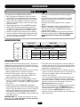
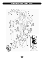
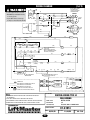
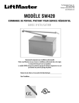
The Chamberlain Group, Inc.
845 Larch Avenue
Elmhurst, Illinois 60126-1196
www.liftmaster.com
BG770 & BG790
INDUSTRIAL-DUTY BARRIER GATE OPERATOR
OWN E R ' S M AN UAL
MODELS BG770 AND BG790 ARE FOR VEHICULAR PASSAGE GATES ONLY
AND ARE NOT INTENDED FOR PEDESTRIAN PASSAGE GATE USE
TABLE OF CONTENTS
SPECIFICATIONS
IMPORTANT NOTES
Operator Specifications. . . . . . . . . . . . . . . . . . . . . . . . . . . . . . . . . 3
Operator Dimensions . . . . . . . . . . . . . . . . . . . . . . . . . . . . . . . . . .3
• BEFORE attempting to install, operate or maintain the operator,
you MUST read and fully understand this manual and follow
ALL safety instructions.
• These instructions are intended to highlight certain safety
related issues. These instructions are not intended to be
comprehensive. Because each application is unique, it is the
responsibility of the purchaser, designer, installer and end user
to ensure that the total gate system is safe for its intended use
OPERATOR WARNINGS
Safety Installation Information . . . . . . . . . . . . . . . . . . . . . . . . . . .4
PREPARATION
Carton Inventory . . . . . . . . . . . . . . . . . . . . . . . . . . . . . . . . . . . . . . 5
Site Preparation . . . . . . . . . . . . . . . . . . . . . . . . . . . . . . . . . . . . . .5
Operation Preparation. . . . . . . . . . . . . . . . . . . . . . . . . . . . . . . . . . 5
INSTALLATION
Pad Mounting . . . . . . . . . . . . . . . . . . . . . . . . . . . . . . . . . . . . . . . . 6
Arm Fabrication . . . . . . . . . . . . . . . . . . . . . . . . . . . . . . . . . . . . . .6
Calculate Arm Length . . . . . . . . . . . . . . . . . . . . . . . . . . . . . . . . . .6
Wiring Specifications . . . . . . . . . . . . . . . . . . . . . . . . . . . . . . . . . .7
Wiring Connections . . . . . . . . . . . . . . . . . . . . . . . . . . . . . . . . . . .7
Arm Attachment . . . . . . . . . . . . . . . . . . . . . . . . . . . . . . . . . . . . 8-9
Arm and Turnbuckle Shaft Adjustments . . . . . . . . . . . . . . . . . . .10
Limit Switch Adjustments. . . . . . . . . . . . . . . . . . . . . . . . . . . . . . 11
WARNING
Mechanical
WARNING
Electrical
OPTIONAL ACCESSORIES
Vehicle Detectors . . . . . . . . . . . . . . . . . . . . . . . . . . . . . . . . . . . .12
Radio Controls . . . . . . . . . . . . . . . . . . . . . . . . . . . . . . . . . . . . . .12
Card Readers, Keypads or Other. . . . . . . . . . . . . . . . . . . . . . . . . 12
Mounting Location . . . . . . . . . . . . . . . . . . . . . . . . . . . . . . . . . . .12
CAUTION
When you see these Safety Symbols and Signal Words on the
following pages, they will alert you to the possibility of SERIOUS
INJURY or DEATH if you do not comply with the warnings that
accompany them. The hazard may come from something
mechanical or from electric shock. Read the warnings carefully.
When you see this Signal Word on the following pages, it will
alert you to the possibility of damage to your gate and/or the gate
operator if you do not comply with the cautionary statements that
accompany it. Read them carefully.
OPERATING INSTRUCTIONS
Electrical Operation. . . . . . . . . . . . . . . . . . . . . . . . . . . . . . . . . . . 13
Manual Operation . . . . . . . . . . . . . . . . . . . . . . . . . . . . . . . . . . . .13
TROUBLESHOOTING
Power . . . . . . . . . . . . . . . . . . . . . . . . . . . . . . . . . . . . . . . . . . . . .14
Accessories. . . . . . . . . . . . . . . . . . . . . . . . . . . . . . . . . . . . . . . . . 14
Primary Voltage Circuit. . . . . . . . . . . . . . . . . . . . . . . . . . . . . . . . 15
Low Voltage Circuit. . . . . . . . . . . . . . . . . . . . . . . . . . . . . . . . . . . 15
General Reference Information . . . . . . . . . . . . . . . . . . . . . . . . . . 15
REPAIR PARTS
Illustrated Parts - Model BG770 . . . . . . . . . . . . . . . . . . . . . . . . . 16
Repair Parts - Model BG770. . . . . . . . . . . . . . . . . . . . . . . . . . . . 17
Illustrated Parts - Model BG790 . . . . . . . . . . . . . . . . . . . . . . . . . 18
Repair Parts - Model BG790. . . . . . . . . . . . . . . . . . . . . . . . . . . . 19
MAINTENANCE
Limited Bearing Lubrication . . . . . . . . . . . . . . . . . . . . . . . . . . . .20
Grease Turnbuckle . . . . . . . . . . . . . . . . . . . . . . . . . . . . . . . . . . .20
WIRING DIAGRAMS
Single Phase Wiring Diagram . . . . . . . . . . . . . . . . . . . . . . . . . . . 21
Three Phase Wiring Diagram . . . . . . . . . . . . . . . . . . . . . . . . . . .22
Control Connection Diagram. . . . . . . . . . . . . . . . . . . . . . . . . . . . 23
WARRANTY POLICY AND SERVICE . . . . . . . . . . . . . . . . 24
2
SPECIFICATIONS
MOTOR
ELECTRICAL
Squirrel cage induction type (3 phase) or capacitor start
induction type (1 phase), continuous duty, 1725 RPM.
Horsepower is designated by second suffix of operator part
number.
-50; 1/2 Horsepower
OVERLOAD PROTECTION
Automatic reset (3 phase operators) or manual reset (1 phase
operators) thermal overload.
ELECTRICAL BOX
NEMA 1 general purpose painted steel enclosure, contains all
motor control equipment. Enclosure removable from operator.
POWER
Line voltage is designated by third suffix of gate part number.
For amp draw, see motor nameplate.
-11; 115Vac, 1 Phase, 60Hz
-21; 230Vac, 1 Phase, 60Hz
-81; 208Vac, 1 Phase, 60Hz
-83; 208Vac, 3 Phase, 60Hz
-23; 230Vac, 3 Phase. 60Hz
-43; 460Vac, 3 Phase, 60Hz
-53; 575Vac, 3 Phase, 60Hz
CONTROL CIRCUIT
Class II, 24Vac
LIMIT SWITCHES
Adjustable, driven limit switches, operate in class II circuit. Not
affected by removal of motor.
POWER ON/OFF SWITCH
Enclosed toggle switch, HP rated.
OPERATION
MECHANICAL
Prewired terminal strip accepts field connection of any access
control device with normally open (N.O.) output contact (most
access control equipment) and when required, a separate
OPEN/CLOSE pushbutton (provided).
Plug-in connectors are included for addition of a loop detector
to open and/or a loop detector to hold open (not provided).
Activation of access device open button, or loop detector to
open will raise gate. Gate will lower automatically unless hold
open loop detector is activated or unless CLOSE button wiring
has been made, in which case gate will remain open until
CLOSE button is pushed.
An optional timer will extend the time that the gate remains
open. AUTO/MANUAL switch holds arm in vertical position.
SPEED REDUCTION
Wormgear-in-oil-bath, 60:1
ARM TYPE
MODEL BG770: One piece type to 15'
MODEL BG790: Counterweighted wishbone type to 24'
ARM SPEED
MODEL BG770: Opens in 4 seconds
MODEL BG790: Opens in 11 seconds
LUBRICATION
Permanently lubricated bearings in motor. Low temperature
gear oil normally never needs replacement. Gear oil is
Mobil SHC 630 or equivalent.
ENCLOSURE
Weatherproof, heavy gauge, pregalvanized steel, powdercoat
finish, top and side access covers with key lock.
Model BG770
17"
MOUNTING
Pad mount
Model BG790
17"
Counterweighted
Wishbone Arm
17"
22"
17"
Up to 15'
35"
44"
Up to 24'
DIMENSIONS
DIMENSIONS
Typical
Installation
Typical
Installation
3
44"
35"
OPERATOR WARNINGS
SAFETY INSTALLATION INFORMATION
1.
Vehicular gate systems provide convenience and security. Gate systems are comprised of many component parts. The gate
operator is only one component. Each gate system is specifically designed for an individual application.
2.
Gate operating system designers, installers and users must take into account the possible hazards associated with each individual
application. Improperly designed, installed or maintained systems can create risks for the user as well as the bystander. Gate
systems design and installation must reduce public exposure to potential hazards.
3.
A gate operator can create high levels of force in its function as a component part of a gate system. Therefore, safety features
must be incorporated into every design. Specific safety features include:
• Gate Edges
• Guards for Exposed Rollers
• Photoelectric Sensors
• Screen Mesh
• Vertical Posts
• Instructional and Precautionary Signage
4.
Install the gate operator only when:
a. The operator is appropriate for the construction and the usage class of the gate.
b. All openings of a horizontal slide gate are guarded or screened from the bottom of the gate to a minimum of 4' (1.2 m) above
the ground to prevent a 2 1/4" (6 cm) diameter sphere from passing through the openings anywhere in the gate, and in that
portion of the adjacent fence that the gate covers in the open position.
c. All exposed pinch points are eliminated or guarded, and guarding is supplied for exposed rollers.
5.
The operator is intended for installation only on gates used for vehicles. Pedestrians must be supplied with a separate access
opening. The pedestrian access opening shall be designed to promote pedestrian usage. Locate the gate such that persons will not
come in contact with the vehicular gate during the entire path of travel of the vehicular gate.
6.
The gate must be installed in a location so that enough clearance is supplied between the gate and adjacent structures when
opening and closing to reduce the risk of entrapment. Swinging gates shall not open into public access areas.
7.
The gate must be properly installed and work freely in both directions prior to the installation of the gate operator.
8.
Controls intended for user activation must be located at least six feet (6') away from any moving part of the gate and where the
user is prevented from reaching over, under, around or through the gate to operate the controls. Outdoor or easily accessible
controls shall have a security feature to prevent unauthorized use.
9.
The Stop and/or Reset (if provided separately) must be located in the line-of-sight of the gate. Activation of the reset control shall
not cause the operator to start.
10. A minimum of two (2) WARNING SIGNS shall be installed, one on each side of the gate where easily visible.
11. For a gate operator utilizing a non-contact sensor:
a. Reference owner’s manual regarding placement of non-contact sensor for each type of application.
b. Care shall be exercised to reduce the risk of nuisance tripping, such as when a vehicle trips the sensor while the gate is
still moving.
c. One or more non-contact sensors shall be located where the risk of entrapment or obstruction exists, such as the perimeter
reachable by a moving gate or barrier.
12. For a gate operator utilizing a contact sensor such as an edge sensor:
a. One or more contact sensors shall be located where the risk of entrapment or obstruction exists, such as at the leading edge,
trailing edge and post mounted both inside and outside of a vehicular horizontal slide gate.
b. One or more contact sensors shall be located at the bottom edge of a vehicular vertical lift gate.
c. A hard wired contact sensor shall be located and its wiring arranged so the communication between the sensor and the gate
operator is not subject to mechanical damage.
d. A wireless contact sensor such as the one that transmits radio frequency (RF) signals to the gate operator for entrapment
protection functions shall be located where the transmission of the signals are not obstructed or impeded by building
structures, natural landscaping or similar obstruction. A wireless contact sensor shall function under the intended end-use
conditions.
e. One or more contact sensors shall be located on the inside and outside leading edge of a swing gate. Additionally, if the bottom
edge of a swing gate is greater than 6" (152 mm) above the ground at any point in its arc of travel, one or more contact sensors
shall be located on the bottom edge.
f. One or more contact sensors shall be located at the bottom edge of a vertical barrier (arm).
4
PREPARATIONS
CARTON INVENTORY
WARNING
1. Unpack the carton, checking for possible damage during
shipping. The arm (when provided) is packed separately.
Damage claims MUST be filed with the freight carrier.
2. Check that the nameplate data (inside service cover) accurately
matches the operator that was ordered.
3. Verify that the following parts are included with the standard
unit.
To reduce the risk of SEVERE INJURY or DEATH, disconnect
power BEFORE performing ANY adjustments.
MODEL BG770 PACKING LIST
PART NUMBER
02-102
07-8007
10-8007M
80-G0187
82-NH38-06
82-HN50-25
82-RH-50
85-LS-50
01-G0674
DESCRIPTION
Open/Close Push Button
Gate Arm Hub
Gate Bracket
Key, 1/2 x 1/2 x 1-3/8
Cone Point Set Screw, 3/8-16 x 3/8
Hex Bolt, 1/2-13 x 2-1/4
Hex Nut, 1/2-13
Split Lock Washer, 1/2
Owner’s Manual
MODEL BG790 PACKING LIST
QTY
1
1
1
1
2
4
4
4
1
PART NUMBER
02-102
07-8007
10-8055
80-G0135
80-G0187
82-HN50-25
82-HN50-28
82-NH38-06
84-RH-50
84-WH-38
85-FW-38
85-FW-50
85-LS-50
01-G0674
SITE PREPARATION
1. Be sure that selected gate location has required clearance for
arm movement (and counterweights on model BG790). Refer to
the dimensional drawings on page 3.
2. Run electrical power to the site according to local electrical
codes (Figure 1). See chart on page 7 for correct wire size and
length of run. If the wire gauge is too high (wire too small) or
the run is too long, the gate may not run properly or may not
run at all. Damage to components may result.
IMPORTANT NOTE: Be sure that the available power is the proper
voltage, phase, frequency, and amperage to supply the gate.
Refer to gate nameplate located inside the service cover.
3. Select locations for control equipment and run any control
wiring that may be needed (such as loop wires, card readers,
ticket spitters, pushbuttons, etc.).
DESCRIPTION
Open/Close Push Button
Arm Hub
Counter Weight Clamp
Threaded Rod, 3/8-16 x 18
Key, 1/2 x 1/2 x 1-3/8
Hex Head Bolt, 1/2-13 x 2-1/4
Hex Head Bolt, 1/2-13 x 3
Cone Point Set Screw, 3/8-16 x 3/8
Hex Nut, 1/2-13
Serrated Flange Nut, 3/8-16
Flat Washer, 3/8
Flat Washer, 1/2
Split Lock Washer, 1/2
Owner’s Manual
QTY
1
2
2
2
2
12
2
4
14
8
8
8
16
1
Figure 1
NOTE: Install line power here. Do not
install line power in panel shown below.
Power switch should be in the OFF position.
OPERATOR PREPARATION
AUTO/MANUAL switch should
be in the “AUTO” position.
1. Remove the wood base from the unit and discard.
2. Locate the keys for the access panel (taped to the arm
mounting flange) and remove.
3. Open the side access panel and check the position of the power
ON/OFF switch.
4. Open the cover of the electrical cabinet and be sure that the
AUTO/MANUAL switch is in the “AUTO” position.
5. OPTIONAL CONTROL EQUIPMENT: If loop detectors, radio
controls, or other control equipment will be added at the site,
do so now. Refer to the instructions in this manual for
installation of factory-provided optional open and/or hold open
loop detectors and for connection of factory-provided optional
radio controls (see Optional Accessories on page 12).
5
INSTALLATION
PAD MOUNTING
Figure 2
1. Layout the concrete pad (Figure 2). Be sure to locate electrical
conduit inside the hatched 14" x 13" area.
2. Excavate required area for pad and conduit. Pad depth should
be below the frost line or as required by local codes.
3. Pour concrete pad. Concrete pad should be level and above the
ground line.
4. Allow the concrete to set at least two days before installing
operator.
5. Secure operator with four concrete anchors (not provided).
20"
14"
Conduit Entry Area
14-1/2"
13"
Arm
ARM FABRICATION
12"
MODEL BG770 (SINGLE ARM)
If you are making the arm yourself, refer to Figure 3 and its
suggestions for the single arm design.
1. Drill four 1/2" diameter holes using the arm clamp as a
template. Tapering the wood as shown helps reduce the
weight and allows you to reduce any warping common
with long lengths of lumber.
2. Cut to desired length. Refer to Calculate Arm Length below.
3. Finish arm with exterior grade paint and stripe with paint or
adhesive backed tape as required.
3"
Length as needed
up to 12'
Figure 3
Material:
6: x 1" Pine or Redwood
5-12"
MODEL BG790 (WISHBONE ARM)
A 24' wishbone arm is provided as standard with every BG790
gate. If a shorter arm is desired, the extension may be shortened
(Figure 4). The maximum arm extension is 8' for a total arm
length of 24'.
1. Cut to desired length. Refer to Calculate Arm Length below.
2. Finish with an exterior grade paint and stripe with paint or
adhesive backed tape as required.
Figure 5
Arm length
22"
Length up to 8'
Figure 4
Arm Extension
Material:
4: x 1" Pine or Redwood
Arm
Output Shaft
CALCULATE ARM LENGTH
To calculate the arm length:
Height to
ceiling
Subtract the height of the output shaft and concrete pad (40")
from the height to ceiling (see Figure 5).
Height of the
output shaft and
concrete pad (40")
EXAMPLE:
If height to ceiling is 8'3" (99"), calculation is as follows:
99" (height to ceiling) - 40" (height of the output shaft and
concrete pad) = 59"
Lower arm should be 59".
6
INSTALLATION
WARNING
To reduce the risk of SEVERE INJURY or DEATH:
• ANY maintenance to the operator or in the area near the
operator MUST not be performed until disconnecting the
electrical power and locking-out the power via the operator
power switch. Upon completion of maintenance the area
MUST be cleared and secured, at that time the unit may be
returned to service.
• Disconnecting power at the fuse box BEFORE proceeding.
Operator MUST be properly grounded and connected in
accordance with local electrical codes. NOTE: The operator
should be on a separate fused line of adequate capacity.
• DO NOT install ANY wiring or attempt to run the operator
without consulting the wiring diagram. We recommend that
you install an optional reversing edge BEFORE proceeding
with the control station installation.
• ALL electrical connections MUST be made by a qualified
individual.
• ALL power wiring should be on a dedicated circuit and well
protected. The location of the power disconnect should be
visible and clearly labeled.
• ALL power and control wiring MUST be run in separate
conduit.
• BEFORE installing power wiring or control stations be sure to
follow ALL specifications and warnings described below.
Failure to do so may result in SEVERE INJURY to persons
and/or damage to operator.
• A ground screw is provided in the switch box for connection
of the power supply ground wire. Failure to properly ground
this unit could result in electrical shock and SERIOUS
INJURY.
WIRING SPECIFICATIONS
SINGLE PHASE
115 Vac
AWG
THREE PHASE
230 Vac
230 Vac
460 Vac
575 Vac
Maximum Length of Wire Run in Feet
6
700
3,100
4,750
14,225
35,550
8
450
1,925
3,000
8,975
22,425
10
275
1,225
1,900
5,650
14,075
12
175
775
1,175
3,525
8,825
WIRING CONNECTIONS
Locate the electrical enclosure inside the cabinet. The enclosure
(shipped loose) may be removed from the cabinet to help in the
connections described below. When all connections are complete,
hang the enclosure as described in step 7.
1. Open the cover of the electrical enclosure. Refer to the wiring
diagram supplied inside for all electrical connections.
2. Be sure that power supply is of the correct voltage, phase,
frequency, and amperage to supply operator. Refer to the
operator nameplate on electrical cabinet cover.
3. Connect power supply wires to the ON/OFF power switch as
shown on the operator wiring diagram. DO NOT connect power
at control panel (L1, L2, L3). Route wires away from belt and
limit switches.
4. A 2-button control station (OPEN/CLOSE) is provided as
standard equipment with every BG770 and BG790 barrier gate.
If you are not using automatic controls to control the gate, the
2-button control station may be connected as shown on the
wiring diagram supplied with the gate to control the gate
manually. However, the AUTO/MANUAL switch should be kept
in the “AUTO” position.
IMPORTANT NOTE: Use 16 gauge wire or larger for all control
wiring connections. If the control wire is too small, damage to
the operator components may result.
5. The control station must be mounted in a location adjacent to
and within clear sight of the gate. If you will mount the control
station outdoors, replace the standard station supplied with the
operator with a weatherproof station.
6. The BG770 and BG790 barrier gates will interface with almost
all types of commonly used control stations, radio controls, and
access control equipment. Refer to the wiring diagram for
connection of these devices.
If you are using a loop detector to open and/or hold open and
close, mounting space and plug-in harnesses are provided in
the electrical cabinet for installation of optional factory supplied
detectors. You may also use other detectors. Refer to the
Optional Accessories section on page 12.
7. When all wiring connections are complete, mount the electrical
enclosure to the shelf housing shelf. MODEL BG770: Hang
electrical enclosure on the two screws provided on the front of
the shelf in the housing. MODEL BG790: Hang electrical
enclosure on the two screws provided on the cross angle under
shelf in the housing.
7
INSTALLATION
ARM ATTACHMENT
WARNING
For easier access during installation, the top cover of the unit may
be opened by removing the two wing nuts from underneath,
inside the cabinet.
When following the procedure below, the motor belt will turn
and the drive shaft will move during some of the steps. Keep
hands and tools out of the gate cabinet and away from the
belt and drive shaft or SERIOUS INJURY may result. Be sure
to DISCONNECT power while installing the arm attachment.
MODEL BG770: STANDARD ARM
Attach arm to the arm hub flange (Figure 5).
MODEL BG770: OPTIONAL ARM
Attach arm to the arm hub flange (Figure 6).
Figure 5
Hub Flange
Gate Arm
Hex Bolt
1/2"-13 x 2-1/4"
Lock Washer and
1/2"-13 Hex Nut
Figure 6
(4) Hex Bolts
Hex Bolt
(2) Flat Washers
See Detail A
(2) Flat Washers
Hex Nut
Extension Arm
DETAIL A
S Screw
Hex Nut
Lift Arm
See Detail B
Hex Nut
Threaded Rod
Hex Bolt
Flat Washer
DETAIL B
8
Flat Washer
Threaded Spacer
Flat Washer
Flat Washer
Hex Bolt
INSTALLATION
MODEL BG790: WISHBONE COUNTERWEIGHTED ARM
1. Bolt counterweights to ends of arms clamps (Figure 7). Use
caution lifting 57 lb. weights.
2. Bend and fasten the two arms together (Figure 8). If an
extension arm is required, sandwich the extension arm
between the two halves of the wishbone arm before bolting
together. Refer to Arm Fabrication on page 6 for extension
arm preparation.
3. Assemble the two 3/8" threaded rods to the arms for center
support.
4. Be prepared for gate to start when you turn the power on. Turn
on power and test the gate.
WARNING
When following the procedure below, the motor belt will turn
and the drive shaft will move during some of the steps. Keep
hands and tools out of the gate cabinet and away from the
belt and drive shaft or SERIOUS INJURY may result. Be sure
to DISCONNECT power while installing the arm attachment.
Figure 7
18-5/8"
30" Radius
Wishbone Arm Arc of Travel
Ensure adequate clearance for travel of arm.
Figure 8
(2) 1/2"-13 Hex Nuts
(2) 1/2" Lock Washers
(2) 1/2" Flat Washers
Extension Arm
See Detail A
(8) 1/2"-13 Hex Nuts
(8) 1/2" Lock Washers
(2) 1/2"-13 x 3" Bolts
(2) 1/2" Flat Washers
(4) 1/2"-13 x 2-1/4"
Bolts
Wishbone Arm
3/8"-16 Nut
3/8" Flat Washer
(2) 3/8"-16 x 18"
Threaded Rods
(8) 3/8"-16 Nuts
(4) 3/8" Lock Washers
(8) 3/8" Flat Washers
(8) 1/2"-13 x 2-1/4"
Hex Bolts
Arm Clamp
Counterweight
(4) 1/2" Flat Washers
(4) 1/2" Lock Washers
(2) 1/2"-13 Hex Nuts
9
INSTALLATION
ARM AND TURNBUCKLE SHAFT ADJUSTMENTS
CAUTION
MODEL BG770 ADJUSTMENTS
1. If necessary, rotate the pulley on the motor by hand until the
crank arm on the gear reducer is perfectly aligned with the
turnbuckle shaft (Figure 9). This is the lowest point of the arm
travel and should be preset in this position at the factory.
2. If the arm is not level, loosen the jam nuts at both ends of the
turnbuckle shaft Insert a screwdriver or other similar tool into
the hole in the shaft. Rotate the shaft either clockwise or
counterclockwise as necessary until the gate arm is in the
desired horizontal position. Retighten jam nuts.
Turn off power BEFORE making ANY adjustments.
Figure 9
Pivot Arm
Jam Nut
MODEL BG770 TURNBUCKLE SHAFT ALIGNMENT
If necessary, align turnbuckle shaft with center of crank arm for
lowest point of travel of pivot arm (Figure 10).
Pulley
Turnbuckle Shaft
Crank Arm
MODEL BG790 ADJUSTMENTS
1. If necessary, rotate the pulley on the motor by hand until the
upper and lower cranks are in a vertical position (Figure 11).
This is the lowest point of travel and should be preset in this
position at the factory.
2. If the arm is not level, loosen the jam nuts on both the top and
bottom end of the turnbuckle shaft.
3. Rotate the shaft either clockwise or counterclockwise as
necessary until the gate arm is in the desired horizontal
position.
NOTE: While the arm is raising, the upper and lower cranks
should travel toward the side access cover.
Figure 10
Figure 11
Turnbuckle Shaft
Jam Nut
Lower Crank Arm
in Closed Position
See Note
Pulley
10
Upper Crank Arm
in Closed Position
INSTALLATION
LIMIT SWITCH ADJUSTMENTS
Figure 12
CLOSE LIMIT SWITCH
The CLOSE limit switch is preset at the factory. If you rotated the
pulley in section Arm and Turnbuckle Shaft Adjustments, you will
need to reset the cam on the CLOSE limit switch.
1. Loosen the set screw on the cam. Then rotate the cam in the
close direction so that the switch is activated when the gate
arm is in its lowest position (Figure 12).
2. When the cam is in the desired position, retighten the set
screw. This adjustment may have to be fine tuned after turning
on power and running the unit for the first time.
Open Limit Switch
Close Limit Switch
Auxiliary Close
Limit Switch
CLOSE
Direction
AUXILIARY CLOSE LIMIT SWITCH
The AUXILIARY CLOSE limit switch is preset at the factory. If you
made an adjustment to the CLOSE cam, you will need to adjust
the cam on the AUXILIARY CLOSE limit switch also.
1. Position the AUXILIARY CLOSE cam slightly ahead of the
CLOSE cam. When the gate arm is on its down travel, the
AUXILIARY CLOSE switch will activate just before the CLOSE
switch.
2. When the cam is in the desired position, retighten the set
screw.
OPEN LIMIT SWITCH
The OPEN limit switch is preset at the factory. This setting may
have to be fine tuned after running the unit for the first time.
1. Loosen the OPEN cam and rotate in the open direction until the
switch is activated (Figure 12).
2. Retighten the cam.
11
OPEN
Direction
OPTIONAL ACCESSORIES
VEHICLE DETECTORS
CAUTION
Almost all types of vehicle detectors may be used in conjunction
with both model BG770 and BG790. More than one detector may
be connected to the gate, and may be mounted inside of the
cabinet. Connect the detector(s) according to the instructions on
the wiring diagrams supplied with the gate and with the detector
itself.
Turn off power BEFORE working inside gate enclosure.
CARD READERS, KEYPADS OR OTHER
FACTORY SUPPLIED PLUG-IN DETECTORS
LiftMaster P/N 71-416-7NH = 24V
PLEASE NOTE: Previous models used 115V detectors
(P/N 71-416-3NH).
Almost all types of access control devices may be connected to
models BG770 and BG790. More than one device may be
connected in parallel. All devices connected according to the
instructions below will open the gate and reverse the gate if it
is closing.
OPEN LOOP DETECTOR
1. Snap the detector onto one set of the four board mount
standoffs located on the inside of the electrical cabinet. Plug the
harness into the connector marked “OPEN.”
2. Connect the two loop wires to terminals P1 and P2 as shown
on the wiring diagram.
MOUNTING LOCATION
Mount or install the access control device within sight of the gate
and according to the instructions supplied with the device. Some
devices require their own power supply. Do not use the 24 volt
power in the gate to supply other devices. Use either direct line
voltage (115V or 230V) or other external power source as
required by the particular device.
NOTE: Most access control devices have an isolated, normally
open output contact to connect to the gate. If yours does not, or if
you are unsure of or unfamiliar with these terms, consult the
supplier of the device or a qualified gate installer.
HOLD OPEN LOOP DETECTOR
1. Snap the detector onto one set of the four board mount
standoffs located on the inside of the electrical cabinet. Plug the
harness into the connector marked “HOLD OPEN.”
2. Connect the loop wires to terminals P3 and P4 as shown on the
wiring diagram.
CONTROL CONNECTION
TURN OFF POWER and connect the two output terminals (or
wires) of the access control device to the terminals #1 and #3 on
the control wiring terminal strip. Use a wiring method that will
provide a permanent, durable and weatherproof connection
between the gate and the access device.
RADIO CONTROLS
All types of standard radio controls may be used in conjunction
with model BG770 and BG790. If the receiver is mounted inside of
the gate enclosure, a commercial coaxial antenna should be used
and extended through the side of the cabinet.
POWER CONNECTION
All radio receivers require a power supply. If the receiver requires
24Vac, you may power the unit from the gate control circuit. To
do this, connect the radio receiver power wires to Terminals #3
and #6 on the control terminal strip. If the receiver requires
115Vac or other power, you will need a separate power source.
A standard residential door radio receiver has a three wire
connection marked 1, 2, 3. If you have this type, you may connect
to operator terminals R3, R1, and R6. The transmitter button will
open the gate if it is fully closed.
CONTROL
If you have a standard residential 3 wire receiver and made the
power connection described above, you are finished with the radio
connections. If you want to use a radio control (such as a single
button), you must order an optional kit (P/N 90-PGR).
12
OPERATING INSTRUCTIONS
ELECTRICAL OPERATION
CAUTION
The BG770 and BG790 barrier gate operators are designed to
provide years of trouble-free operation. The gate may be operated
by means of the two button control station, or by other means if
provided.
Keep hands clear of moving parts. The motor will start when
AUTO/MANUAL switch is flipped to the “MANUAL” position.
ON/OFF POWER SWITCH
The gate is provided with an ON/OFF power switch. To shut power
off, remove the access cover and move the toggle switch on the
right side of the main electrical cabinet to the “OFF” position.
OVERLOAD PROTECTION
The motor is protected by either a manual reset (Single Phase
unit) or automatic reset (3 phase unit) thermal overload protector.
The overload protector will trip when the motor temperature is too
hot.
DO NOT ATTEMPT TO BYPASS THIS UNIT
If the overload trips, the gate could start by itself when the
overload is reset (either manual or automatic). Exercise caution
when resetting the overload. On one phase units, the reset
button is located on the cover of the electrical cabinet.
If after resetting, the overload continues to trip, consult a qualified
service company.
MANUAL OPERATION
ACCESS CONTROL “EMERGENCY” BYPASS
To open the gate in an emergency, remove the keyed access cover
and open the electrical cabinet. Flip the AUTO/MANUAL switch to
the “MANUAL” position.
The gate arm will remain in the up position, and no other control
device will have any effect until the switch is set back to the
“AUTO” position.
13
TROUBLESHOOTING
ACCESSORIES
When troubleshooting, one of the first things to do is try to isolate
the problem area. The four (4) main areas to check out are:
• Power
• Accessories
• Operator’s Primary Voltage
• Operator’s Low Voltage
Add-on accessories can create many of the problems that are
credited to the operator. Many applications have more than one
accessory item attached to the operator and some of these items
even draw their power from the operator.
Some of the symptoms that can show up because of accessories:
• The operator will not close.
• The operator will not open. The operator will not run.
• The operator begins to run, then stops or reverses.
Whenever the problem is thought to be an accessory and there
are more than one connected to the operator, always disconnect
one accessory at a time and then test the system. This will
hopefully isolate which item is causing the problem.
If an accessory item is being used as an access control device
(used to open or close), falls in the closed position or sends out a
continuous signal. The operator will hold the gate in one position
until the signal from the accessory is removed.
In some applications, the gate may begin to move then either stop
or stop and reverse within a couple of seconds. This can be
caused by an external obstruction device that has failed.
If there are many accessories attached to and powered by the
operator, there may be too much current draw for the operator’s
control transformer. This operator can only supply approximately
2 amps @ 24Vac. Double check all accessories for their current
requirements.
POWER
Always use extreme caution! Some possible symptoms of power
problems include:
• The obvious one is - the operator will not run.
• The operator runs slow.
• Circuit breakers or fuses keep tripping.
• Motor overload keeps tripping.
• Operator starts but then stops.
Using a volt-ohmmeter, take a voltage reading at the control
transformer’s primary terminals. You should get a reading as
follows:
Nominal Voltage
Minimum
Maximum
120V
108
132
230V
207
253
460V
414
506
If you get a reading that does not fall into the minimum/maximum
area, then check out your main power supply. Also, make sure
that the operator was ordered with the proper voltage and phase.
Another item to check is the wire run from the power supply to
the operator. Double check the gauge of the wire versus the
distance.
If the voltage reading is okay from 1A, then take the same voltage
reading with the operator running. If voltage drops below the
minimum with this reading, then there could be an excessive
current draw somewhere, or a wire AWG is too small.
In some cases, power drops can occur at only specific times
during the day or night. This can be caused by increased power
demands in a general area at a specific time-particularly areas
undergoing rapid growth.
14
TROUBLESHOOTING
PRIMARY VOLTAGE CIRCUIT
Figure 13
Contactor
Use extreme caution when troubleshooting the primary voltage
circuit! There are five (4) items in this circuit that could be
causing trouble, and they are:
• Motor
• Transformer
• Contactor (Figure 13)
• Power Disconnect Switch
The first thing to check is the incoming power. Is it there at the
incoming side of the power disconnect switch?
If there is power, then check for it at the transformer primary
terminals. If there is voltage at the switch and none at the
transformer, then you probably have a bad power disconnect and
it should be replaced. Check secondary output of transformer for
24Vac output.
If the first two check out okay, then manually disconnect the
operator from the gate. Very carefully, using a screwdriver with
an insulated handle, press down on the open side of the
contactor. Then do the same to the close side of the contactor.
Did the operator run in both directions? If it did, the problem may
be in the low voltage control circuit. It if did not, then the problem
is either in the contactor or the motor.
If the contactor is suspected to be causing the problem, first
carefully check all wiring connections at the contacts (Figure 13).
Disconnect Power! Using a volt-ohmmeter, take continuity
readings across the contacts of the contactor. Remove wires from
one side of the contactor. Place one probe on 1 and the other
on 2. You should get NO continuity; now press down on the
contactor; you should get a continuity reading. Repeat this on all
of the contactor’s contact points.
If the problem is thought to be the motor, it is recommended that
it be replaced. It is possible that the thermal overload inside the
motor has overheated. Wait approximately 15 minutes, then try
running unit.
NOTE: Some motors have the overload built into the motor itself,
while other units have a separate overload in the controller
(Model BG770 uses a manual reset overload).
LOW VOLTAGE CIRCUIT
The first thing to check is the circuit breaker.
The secondary voltage must be between 22 and 30Vac. This
voltage can be checked at the circuit board at terminals 3 and 6.
The contactor coils receive 24Vac. To activate the motor in either
the open or close direction. There are two contactor coils (one for
open and one for close).
The limit switches are S.P.D.T. (single pole, double throw). These
limit switches tell the operator to shut off at either the full open or
full close position.
GENERAL REFERENCE INFORMATION
THE GATE
Double check the gate and its related hardware. Does the
gate move freely? Are there unprotected pinch points? If yes,
then correct.
WIRING DIAGRAM
Always reference the wiring diagram that was supplied with the
operator. Note that some of the accessory items may have their
own wiring diagram.
If you cannot correct the problem or if you feel you will require
technical assistance, contact your local distributor or dealer. If you
do not have a distributor or dealer, then contact us for technical
assistance. Please when calling for assistance, make sure you
have the gate operator model number, voltage, phase, horsepower
and a list of all accessories that are attached to the operator.
15
ILLUSTRATED PARTS - MODEL BG770
10
8
30
43
5
14
22
44
29
38
34
15
35
9
3
17
41
31
45
2
19
4
40
42
16
36
11
39
6
46
27
18
28
20
24
7
37
13
48
9
12
23
33
25
21
26
47
1
32
Operator Assembly
16
REPAIR PARTS - MODEL BG770
INDIVIDUAL PARTS
ITEM PART #
1
03-8024-K
2
07-8003
3
07-8004
4
07-8005
5
07-8007
6
10-3522
7
10-8001-T
8
10-8007-M
9
10-8014
10 10-8016-T
11 10-8017-T
12 10-8021
13 10-8022
14 11-8031
15 12-8032
16 12-8033
17 12-8034
18 16-8001
19 17-2001
20 17-2002
21 21-3260-1
22 23-2017
23 23-2761
24 23-8001
25 24-24-1
27 28-3000
28 28-8003
29 31-10-17
30 31-2712
31 32-8002
32 42-110
33 42-110-2
34 65-1209
35 80-1003
36 80-575
37 80-8001
38 82-HN52-18
39 82-HN75-28
40 84-JH-76
41 84-JH-76L
42 84-RH-75
43 85-FW-50
44 85-LS-50
45 91-G0122
NOT SHOWN
02-102
03-ABDIN-4
13-8000
13-8001
42-3608
74-G0120
80-1904N
80-207-36
80-5001
80-G0186
INDIVIDUAL PARTS
DESCRIPTION
3 Pole Contactor
Lower Crank
Upper Crank
Crank Link
Gate Arm Hub
Reducer Shim
Tan Barrier Gate Enclosure
Gate Bracket
Switch Bracket
Tan Top Cover
Tan Access Cover
Electrical Panel
Elec. Panel Mounting Bracket
Shaft
4 Bolt Flange
Female Rod End
Female Rod End
V-Belt
8" Pulley
2" Pulley
Transformer
SPDT Limit Switch
Rocker Switch
Toggle Outlet
24Vac DPDT Relay
Switch Box
Duplex Outlet Cover
1-32 x 1/8 Spacer
Nylon Sensor Spacer
Barrier Gate Gear Reducer
8 Position Terminal Block
10 Position Terminal Block
Single Arm (Optional)
6-32 Tinnerman Nut
3/4 Flat Washer
Access Panel Lock
1/2-20 x 1-1/4 Hex Head Bolt
3/4-10 x 3 Hex Head Bolt
3/4-16 Jam Nut
3/4-16 Left Hand Jam Nut
3/4-10 Hex Nut
1/2 Flat Washer
1/2 Split Flat Washer
Limit Collar
QTY
1
1
1
1
1
2
1
1
1
1
1
1
1
1
2
1
1
1
1
1
1
3
1
1
1
1
1
2
6
1
1
1
1
1
6
1
8
1
1
1
1
6
12
4
Key Switch
DIN Rail
Metal Gasket
Rubber Grommet
8 Position Terminal Block
115V Control Box
Failsafe Board Stand Off
1/4 x 1/4 x 1-1/4 Key
3/16 x 3/16 x 3/4 Key
1/2 x 1/2 x 1-3/4 Key
1
1
14
1
1
1
8
1
2
1
ITEM PART #DESCRIPTION
QTY
NOT SHOWN
80-G0187
1/2 x 1/2 x 1-3/8 Key
1
81-8000
Shock Mount
8
81-PX06-06T 6-32 x 3/8 Self Tapping Screw
6
82-CB31-26 5/16-18 x 2-1/2 Carriage Bolt
4
82-HN25-08 1/4-20 x 1/2 Hex Head Bolt
2
82-HN25-18 1/4-20 x 1-1/4 Hex Head Bolt
4
82-HN31-16 5/16-18 x 1 Hex Head Bolt
4
82-HN38-24 3/8-16 x 2 Hex Head Bolt
4
82-HN50-25 1/2-13 x 2-1/4 Hex Head Bolt
4
82-NH31-06 5/16-18 x 3/8 Set Screw
1
82-NH38-06 3/8-16 x 3/8 Cone Point Set Screw 4
82-PX06-28 6-32 x 3 Pan Head Slotted Screw 2
82-PX08-04T 8-32 x 1/4 Self Tapping Screw
6
82-PX08-10T 8-32 x 5/8 Self Tapping Screw
4
82-QN31-12 5/16-18 x 3/4 Square Head Bolt
2
82-QN75-26 5/16-18 x 3/4 Square Head Bolt
1
82-RS10-20 10-32 x 1-1/2 Slotted Screw
2
84-JH-75
3/4-10 Jam Nut
1
84-RH-50
1/2-13 Hex Nut
4
84-WH-10
10-32 Serrated Washer Head Nut 2
84-WH-25
1/4-20 Serrated Flange Nut
12
84-WH-31
5/16-18 Serrated Flange Lock Nut 8
84-WH-38
3/8-16 Serrated Flange Lock Nut
4
84-WN-25
1/4-20 Wing Nut
2
85-FW-31
5/16 Flat Washer
4
85-FW-38
3/8 Flat Washer
4
85-LS-75
3/4 Split Lock Washer
2
91-G0128
Electrical Enclosure
1
VARIABLE PARTS
ITEM PART #
DESCRIPTION
QTY
46 20-XXXXX-X Motor
1
20-1050B-2P 1/2HP - 115/208/230Vac - 10-60Hz
Used on: BG770-50-11,
BG770-50-21, BG770-50-81
20-3050B-4E 1/2HP - 208/230/460Vac - 30-60Hz
Used on: BG770-50-23,
BG770-50-43, BG770-50-83
20-3050M-5 1/2HP - 575Vac - 30-60Hz
Used on: BG770-50-53
47 24-XXX-X
Relay
1
24-115-1
115Vac Relay
Used on: All 115Vac, 10 Models
24-230-5
208/230Vac Relay
Used on: All 208/230Vac,
10 Models
48 25-XXXX
Fuse
1
25-2006
6A Fuse
Used on: BG770-50-21
25-2010
10A Fuse
Used on: BG770-50-11
17
ILLUSTRATED PARTS - MODEL BG790
12
33
7
14
2
34
2
33
41
4
40
34
15
12
3
28
13
14
29
42
44
25
45
40
39
43
16
44
23
38
5
8
45
44
14
10
17
35
46
37
18
30
14
36
47
20
19
21
6
24
32
11
9
49
1
22
31
26
Operator Assembly
(Wishbone Arm not shown)
32
27
48
18
REPAIR PARTS - MODEL BG790
INDIVIDUAL PARTS
ITEM PART #
1
03-8024-K
2
07-8007
3
07-8058
4
07-8063
5
07-8064
6
10-8014
7
10-8016-T
8
10-8017-T
9
10-8021
10 10-8026
11 10-8051-T
12 10-8055
13 11-8061
14 12-8032
15 12-8033
16 12-8034
17 15-5032
18 15-9020
19 16-8002
20 17-2001
21 17-2002
22 21-3260-1
23 23-2017
24 23-2761
25 23-8001
26 24-24-1
27 24-24-6
28 28-3000
29 28-8003
30 32-8002
31 42-110-2
32 42-3608
33 65-1208
34 65-8056
35 80-1003
36 80-207-36
37 80-8001
38 82-HN52-18
39 82-HN52-20
40 82-HN75-26
41 82-NH38-06CP
42 84-JH-76
43 84-RH-75
44 85-FW-50
45 85-LS-50
46 91-G0122
NOT SHOWN
02-102
03-ABDIN-4
10-8027
11-8062
13-8000
13-8001
19-5051
19-9024
19-9025
31-10-17
31-2712
74-G0133
80-1904N
80-5001
80-575
INDIVIDUAL PARTS
DESCRIPTION
QTY
3 Pole Contactor
1
Arm Hub
2
Crank Link
1
Upper Crank
1
Lower Crank
1
Switch Bracket
1
Tan Top Cover
1
Tan Access Cover
1
Electrical Panel
1
Bearing Plate
1
Tan Housing
1
Counterweight Clamp
2
Main Shaft
1
4 Bolt Flanged Bearing
5
Female Rod End
1
Female Rod End
1
50B32 Sprocket
1
50B12 Sprocket
1
Cogged Belt
1
8" Pulley
1
2" Pulley
1
Transformer
1
SPDT Limit Switch
3
Rocker Switch
1
Toggle/Outlet Combination
1
24Vac DPDT Relay
1
3 PDT 24V Relay
1
Switch Box
1
Duplex Outlet Cover
1
Gear Reducer
1
10 Position Terminal Block
1
8 Position Terminal Block
1
Wishbone Arm
1
Counterweight Kit
1
6-32 Tinnerman Nut
1
1/4 x 1/4 x 1-1/4 Disconnect Key 1
Access Panel Lock
1
1/2-20 x 1-1/4 Hex Head Bolt
18
1/2-20 x 1-1/2 Hex Head Bolt
6
3/4-10 x 2-1/2 Hex Head Bolt
2
3/8-16 x 3/8 Cone Point Set Screw 8
3/4-16 Jam Nut
1
3/4-10 Hex Nut
2
1/2 Flat Washer
24
1/2 Split Lock Washer
38
Limit Collar
4
Open/Close Key Switch
DIN Rail
Electrical Panel Hanger Kit
Intermediate Shaft
Metal Gasket
Rubber Grommet
#50 Chain
#50 Chain Master Link
#50 Chain Half Link
1-32 x 1-1/8 Spacer
Nylon Sensor Spacer
Control Box
Failsafe Board Stand Off
3/16 x 3/16 x 1-3/4 Key
3/4 Flat Washer
ITEM PART #
DESCRIPTION
NOT SHOWN
80-G0135
3/8-16 x 18 Threaded Rod
80-G0185
1/2 x 1/2 x 2-1/2 Key
80-G0187
1/2 x 1/2 x 1-3/8 Key
80-G0188
1/2 x 1/2 x 2 Key
80-G0211
5/16 x 1-1/4 Stud
81-8000
Shock Mount
82-CB31-26
5/16-18 x 2-1/2 Carriage Bolt
82-HN25-08 1/4-20 x 1/2 Screw
82-HN25-18 1/4-20 x 1-1/4 Screw
82-HN31-16 5/16-18 x 1 Hex Head Bolt
82-HN50-20 1/2-13 x 1-1/2 Hex Head Bolt
82-HN50-25 1/2-13 x 2-1/4 Hex Head Bolt
82-HN50-28 1/2-13 x 3 Hex Head Bolt
82-NH31-06CP 5/16-18 x 3/8 Set Screw
82-PX06-06T 6-32 x 3/8 Self Tapping Screw
82-PX06-28
6-32 x 3 Screw
82-PX08-04T 8-32 x 1/4 Self Tapping Screw
82-PX08-10T 8-32 x 5/8 Self Tapping Screw
82-RS10-20 10-32 x 1-1/2 Screw
82-SH10-18 10-32 x 1-1/4 Screw
84-JH-76L
3/4-16 Left Hand Jam Nut
84-RH-50
1/2-13 Hex Nut
84-WH-10
10-32 Serrated Washer Nut
84-WH-25
1/4-20 Serrated Flange Nut
84-WH-31
5/16-18 Serrated Flange Lock Nut
84-WH-38
3/8-16 Serrated Flange Nut
84-WN-25
1/4-20 Wing Nut
85-FW-31
5/16 Flat Washer
85-FW-38
3/8 Flat Washer
85-LS-31
5/16 Split Lock Washer
85-LS-75
3/4 Split Lock Washer
91-G0128
Electrical Enclosure
94-G0233
Power Cable
94-G0234
Motor Cable
QTY
2
1
3
1
4
8
4
2
4
4
4
12
2
1
6
2
6
4
2
2
1
18
10
14
12
8
2
8
12
4
2
1
1
1
VARIABLE PARTS
ITEM PART #
DESCRIPTION
QTY
47 20-XXXXX-X Motor
1
20-1050B-2P 1/2HP - 115/208/230Vac - 10-60Hz
Used on: BG790-50-11,
BG790-50-21, BG790-50-81
20-3050B-4E 1/2HP - 208/230/460Vac - 30-60Hz
Used on: BG790-50-23,
BG790-50-43, BG790-50-83
20-3050M-5 1/2HP - 575Vac - 30-60Hz
Used on: BG790-50-53
48 24-XXX-X
Relay
1
24-115-1
115Vac Relay
Used on: All 115Vac, 10 Models
24-230-5
208/230Vac Relay
Used on: All 208/230Vac,
10 Models
49 25-XXXX
Fuse
1
25-2006
6A Fuse
Used on: BG790-50-21
25-2010
10A Fuse
Used on: BG790-50-11
1
1
1
1
14
2
1
1
1
2
6
1
8
1
4
19
MAINTENANCE
IMPORTANT SAFETY INSTRUCTIONS
WARNING
To reduce the risk of SEVERE INJURY or DEATH:
1. READ AND FOLLOW ALL INSTRUCTIONS.
2. NEVER let children operate or play with gate controls.
Keep the remote control away from children.
3. ALWAYS keep people and objects away from the gate.
NO ONE SHOULD CROSS THE PATH OF THE MOVING
GATE.
4. Test the gate operator monthly. The gate MUST reverse
on contact with a rigid object or stop when an object
activates the non-contact sensors. After adjusting the
force or the limit of travel, retest the gate operator.
Failure to adjust and retest the gate operator properly
can increase the risk of INJURY or DEATH.
5. Use the emergency release ONLY when the gate is not
moving.
6. KEEP GATES PROPERLY MAINTAINED. Read the
owner’s manual. Have a qualified service person make
repairs to gate hardware.
7. The entrance is for vehicles ONLY. Pedestrians MUST
use separate entrance.
8. Disconnect ALL power BEFORE performing ANY
maintenance.
9. ALL maintenance MUST be performed by a LiftMaster
professional.
SAVE THESE INSTRUCTIONS.
10.
CHECK AT LEAST ONCE EVERY
DESCRIPTION
External Safety Systems
Gate Caution Systems
Drive Chain (see notes)
Sprockets and Pulleys
Gate
Accessories
Electrical
Frame Bolts
Total Unit
TASK
1 MONTH
Check for proper operation
Make sure they are present
Check for excessive slack and lubricate
Check for set screw tightness
Inspect for wear or damage
Check all for proper operation
Inspect all wire connections
Check for tightness
Inspect for wear or damage
6 MONTHS
X
X
X
X
X
X
X
X
12 MONTHS
X
X
X
X
X
X
X
X
X
LIMITED BEARING LUBRICATION
NOTES:
• Inspection and service should always be performed anytime a
malfunction is observed or suspected.
• Limit switches may have to be reset after any major drive chain
adjustments.
• BG790: If lubricating chain, use only a proper chain lube spray
or a lightweight motor oil. Never use grease or silicone spray.
• When servicing, please do some “house cleaning” of the
operator and the area around the operator. Pick up any debris
in the area. Clean the operator if needed.
• Severe or high cycle usage will require more frequent
maintenance checks.
• It is suggested that while you are at the site, take some voltage
readings of the operator. Using a VOM, double check the
incoming voltage to the operator to make sure it is within ten
percent of the operator’s rating.
• While you are at the site, now would be a good time to let the
owner or manager know about any new items available or any
safety items that could and should be added to the site.
The barrier gates require very little in the way of maintenance.
Motor and shaft bearing normally should not require lubrication.
The gear oil in the gear reducer is sealed in. Unless a severe
problem causes a seal to break, it should never need replacement.
If gear oil is required, use Mobilube C SAE140 or equivalent.
GREASE TURNBUCKLE
Periodically grease the ball ends of the turnbuckle, depending on
the gate’s frequency of use.
20
WIRING DIAGRAM
(1 of 2)
MOTOR CONNECTION SAME
AS INCOMING POWER.
FOR BG770, INTERCHANGE
GREEN AND RED WIRES
(GN)
(W)
To protect against fire and electrocution:
• DISCONNECT power BEFORE installing
or servicing operator.
• Replace ONLY with fuse of same type
of rating. Fuse 3.2A, 3AG, 250V, SLO-BLO
(W)
L2
1 PHASE
INCOMING LINE
(SEE NOTE 3)
(BK)
4
115V ONLY
4
L1
(BK)
2
SEE NOTE 2
H1
OP
115V MOTOR
CONNECTION
6
OP
3
1
CL
Y
(BK)
6
OP
CL
BL
3
5
(GN)
W
4
R
8
BR
115V ONLY
115V
ACCESSORIES
O/L SEE
NOTE 4
8
BK
5
OR
1
(W)
BR
(R)
1
W
2
4
BR
(BK)
2
(BK)
IR
(W)
5
3
(GN)
0/L
(BK)
CL
(OR)
(BK)
230V ONLY
BK
(W)
(BK)
5
BR
H2
Y
2
O/L SEE
NOTE 4
BL
3
OR
1
(R)
(W)
230V MOTOR
CONNECTION
SEE NOTE 1
(YEL)
(YEL)
(BL)
FUSE 3.2A
24V SEC.
AUTO/MANUAL
(W)
OPEN
OPEN LOOP–PRESENCE
(GN)
J3–4
(W)
J3–6
SENSING
EDGE
AUX.
CLOSE L/S
(OPTIONAL)
3
(W)
7
(GY)
(PUR)
1
(BR)
(OR)
(OR)
(OR)
R1
14
R1
R2
(GN)
OP
(GN)
24V COIL
2) REMOVE JUMPER TO CAUSE GATE
ARM TO CLOSE IMMEDIATELY UNLESS
HOLD OPEN LOOP IS ACTIVATED.
5
(OR)
(OR)
13
OP
IR
(Y)
6
R1
1) REMOVE JUMPER WHEN TIMER TO
CLOSE IS USED.
(OR)
OPEN L/S
(BL)
C
NO
24V COIL
CLOSE
HOLD OPEN
LOOP–PRESENCE
(GN)
J4–6
J4–4
(GY)
10
CL
(OR)
14
(BL)
R2
(OPTIONAL)
24V COIL
(R)
13
(R)
(BR)
IR
2
8
(R)
R2
(BK)
(W)
R1
CLOSE L/S
(PUR)
CL
9
(BL)
C
NO
24V COIL
TIMER
(OPTIONAL)
ADD JUMPER WHEN USING CLOSE BUTTON
DO NOT USE WITH HOLD OPEN LOOP
REMOVE JUMPER WHEN
TIMER IS ADDED
(R)
J3–9
TERMINAL BLOCK
J3–10
WIRE CONNECTION FOR STANDARD CONTROL DEVICES
WIRE CONNECTION FOR OPTIONAL DEVICES
WIRE CONNECTION FOR 230V UNITS ONLY
J3
IS CONNECTOR FOR 24V OPEN LOOP DETECTOR
J4
IS CONNECTOR FOR 24V HOLD OPEN LOOP DETECTOR
J4–9
J4–10
(BRN)
OPEN LOOP
LOOP WIRES
(OPTIONAL)
P1
(GY)
P2
(BRN)
(GY)
24V OPEN
LOOP
HOLD OPEN LOOP
LOOP WIRES
(OPTIONAL)
P3
P4
J3–7
(R)
J4–7
24V HOLD
OPEN LOOP
(BK)
(BK)
J4–8
J3–8
(OPTIONAL EQUIPMENT)
1
NOTES:
APPLICATIONS:
1) TRANSFORMER PRIMARY VOLTAGE SAME AS OPERATOR LINE VOLTAGE
24V SECONDARY.
2) RELAY COIL VOLTAGE SAME AS OPERATOR LINE VOLTAGE.
3) WE RECOMMEND USING A DEDICATED CIRCUIT BREAKER FOR EACH OPERATOR.
4) BROWN WIRES INSIDE MOTOR NOT USED, SHOULD BE WIRE NUTTED.
CONTROL WIRING TYPE L2
FIELD WIRING
MODEL TYPES:
BG770, BG790
HORSEPOWER:
1/2
VOLTAGE/PHASE:
115/230V, 60Hz, 1 PHASE ONLY
DRAWING NUMBER:
DATE:
21
08/28/00
01-G1014
REVISION:
F-3/20/08
ECN:
08-7165
(1 of 2)
WIRING DIAGRAM
(GN)
(GN)
To protect against fire and electrocution:
• DISCONNECT power BEFORE installing
or servicing operator.
• Replace ONLY with fuse of same type
of rating. Fuse 3.2A, 3AG, 250V, SLO-BLO
(BL)
(R)
(BK)
(W) (BL)
(BK)
L1
CL
3–PHASE
INCOMING LINE
(SEE NOTE 2)
4
OP
(W)
5
3
(R)
OP
4
(BK)
L3
(W)
1
CL
2
(W)
CL
H1
(BL)
(R)
(W)
1
6
(W)
(W)
3
9
4
J
480V MOTOR
CONNECTION
5
6
J
2
3
OP
8
MOTOR CONNECTION SAME
AS INCOMING POWER
(GN)
(BK)
L2
7
2
(W)
6
(W)
(W)
1
(BL)
(W)
1
7
2
8
4
5
3
9
6
J
J
208/230V
MOTOR
CONNECTION
5
(GN)
WIRE COLOR: 208V–(R),
230V–(OR), 480–(VT),
575V–(GY)
115V
GEARBOX
HEATER
(BK)
J
575V MOTOR
CONNECTION
2
3
(BL)
(W)
H2
1
(BL)
(R)
J
(OPTIONAL EQUIPMENT)
SEE NOTE 1
(YEL)
4
FUSE 3.2A
J1
O/L IN
MOTOR
(OR)
J2
24V SEC.
AUTO/MANUAL
(YEL)
(BL)
(W)
OPEN
(OR)
(GN)
SENSING
EDGE
3
OPEN LOOP–PRESENCE
J3–6
J3–4
AUX.
(OPTIONAL)
(W) CLOSE L/S
7
R1
(OR)
(OR)
(OR)
14
OP
(GN)
R2
(W)
GY
5
24V COIL
24V COIL
TD–2
(OR)
OP
24V COIL
R1
(BL)
C
24VAC
DPDT
HOLD OPEN
LOOP–PRESENCE
J4–4
(GY)
(W)
(BL)
10
J4–6
R2
(OPTIONAL)
CL
CLOSE L/S
NO
TD1
CLOSE
(OR)
(OR)
(OR)
(Y)
(GN)
(BR)
R1
1) REMOVE JUMPER WHEN TIMER TO
CLOSE IS USED.
2) REMOVE JUMPER TO CAUSE GATE
ARM TO CLOSE IMMEDIATELY UNLESS
HOLD OPEN LOOP IS ACTIVATED
(GN)
(OR)
13
(PUR)
1
24V COIL
(R)
13
14
2
(BR)
8
(R)
R2
(W)
9
(BK)
R1 (PUR) TD1 (PUR)
24V COIL
TIMER
(OPTIONAL)
CL
(PUR) CLOSE
NO
L/S
C
(BL)
TD2
REMOVE JUMPER WHEN
TIMER IS ADDED
ADD JUMPER WHEN USING CLOSE BUTTON
DO NOT USE WITH HOLD OPEN LOOP
24VAC
DPDT
(BK)
J3–9
TERMINAL BLOCK
J3–10
WIRE CONNECTION FOR STANDARD CONTROL DEVICES
WIRE CONNECTION FOR STANDARD CONTROL DEVICES
J3
IS CONNECTOR FOR 24V OPEN LOOP DETECTOR
J4
IS CONNECTOR FOR 24V HOLD OPEN LOOP DETECTOR
J4–9
J4–10
(BRN)
(GY)
OPEN LOOP
LOOP WIRES
(OPTIONAL)
P1
P2
(BRN)
(GY)
HOLD OPEN LOOP
LOOP WIRES
(OPTIONAL)
P3
P4
24V OPEN
LOOP
J3–7
(BK)
J4–7
24V HOLD
OPEN LOOP
(R)
(R)
J4–8
J3–8
(OPTIONAL EQUIPMENT)
1
NOTES:
APPLICATIONS:
1) TRANSFORMER PRIMARY VOLTAGE SAME AS OPERATOR LINE VOLTAGE
24V SECONDARY
CONTROL WIRING TYPE
FIELD WIRING & ADJUSTMENTS
2) WE RECOMMEND USING A DEDICATED CIRCUIT BREAKER FOR EACH OPERATOR.
MODEL TYPES:
HORSEPOWER:
VOLTAGE/PHASE:
DRAWING NUMBER:
DATE:
22
08/28/00
BG770 (PG) BG790 (HBG)
1/2
208/230/480/575V
01-G1015
REVISION:
E-3/20/08
ECN:
08-7165
CONTROL CONNECTION DIAGRAM
IT IS IMPORTANT TO READ ALL SAFETY RULES INCLUDED IN THE INSTALLATION MANUAL BEFORE
BEGINNING INSTALLATION. FAILURE TO COMPLY WITH THE SAFETY INSTRUCTIONS MAY RESULT
IN SERIOUS PERSONAL INJURY OR PROPERTY DAMAGE.
CONTROL WIRING
LINE VOLTAGE SUPPLY
ON
SWITCH
(BK)
MANUAL
OPEN
OFF
(W)
115V
OUTLET
SEE
NOTE #3
SEE
NOTE #1
SEE NOTE #2
SENSING EDGE
(GN)
OPEN BUTTON
OR OTHER
OPEN CONTROL
CLOSE BUTTON
SEE NOTE #2
1 PHASE
INCOMING LINE
ELECTRICAL CABINET
(SEE NOTE #5)
(W)
SWITCH
(BK)
ON
(R)
OFF
(GN)
WARNING
(SEE NOTE #5)
115V
ACCESSORIES
(0.2A MAX)
OPEN
LOOP
HOLD OPEN
LOOP
LOOP WIRE CONNECTIONS FOR
FACTORY SUPPLIED (PLUG-IN)
DETECTORS ONLY
LOOP DETECTORS BY OTHERS
RADIO CONTROL
CONNECTIONS FOR LOOP DETECTORS
NOT SUPPLIED BY THE FACTORY
PRESENCE CONTACT OF
LOOP TO OPEN
3 PHASE
INCOMING LINE (SEE NOTE #5)
CONNECTIONS FOR STANDARD
3-WIRE 24 VAC RADIO CONTROL
PRESENCE CONTACT OF
LOOP TO HOLD OPEN
RADIO CONTROL WILL OPEN GATE
AND REVERSE IF CLOSING. IT WILL
NOT STOP OR CLOSE THE GATE.
LOOP WIRES AND POWER FOR LOOP DETECTORS
SHOULD BE DIRECTLY WIRED TO DETECTOR ITSELF.
REFER TO INSTRUCTIONS ACCOMPANYING DETECTOR.
NOTES:
1) REMOVE THIS JUMPER TO CAUSE GATE ARM TO CLOSE IMMEDIATELY WHENEVER IT IS OPENED, UNLESS A VEHICLE IS ON THE
HOLD OPEN LOOP. IF THIS JUMPER IS NOT REMOVED, ARM WILL REMAIN OPEN UNTIL A VEHICLE ENTERS AND EXITS THE HOLD
OPEN LOOP.
2) ADD JUMPER FROM TERMINAL #8 TO #9 WHENEVER CLOSE BUTTON IS USED. DO NOT USE WITH HOLD OPEN LOOP.
3) 115V UTILITY OUTLET (4 AMP MAX.) PROVIDED ON 115V MODELS ONLY.
4) SEE REVERSE SIDE FOR INTERNAL OPERATOR WIRING.
5) DO NOT CONNECT INPUT POWER LINES TO L1 & L2 TERMINALS. POWER LINES MUST BE CONNECTED TO THE POWER SWITCH.
23
WAR RA NTY POL I CY AND S E RVI CE
LIFTMASTER® TWO YEAR LIMITED WARRANTY
The Chamberlain Group, Inc. warrants to the final purchaser of this product, for the structure in which this product is originally
installed, that it is free from defect in materials and/or workmanship for a period of two years from the date of purchase. The proper
operation of this product is dependent on your compliance with the instructions regarding installation, operation, maintenance and
testing. Failure to comply strictly with those instructions will void this limited warranty in its entirety.
If, during the limited warranty period, this product appears to contain a defect covered by this limited warranty, call 1-800-528-2806,
toll free, before dismantling this product. Then send this product, pre-paid and insured, to our service center for warranty repair. You
will be advised of shipping instructions when you call. Please include a brief description of the problem and a dated proof-of-purchase
receipt with any product returned for warranty repair. Products returned to Seller for warranty repair, which upon receipt by Seller are
confirmed to be defective and covered by this limited warranty, will be repaired or replaced (at Seller’s sole option) at no cost to you
and returned pre-paid. Defective parts will be repaired or replaced with new or factory-rebuilt parts at Seller’s sole option.
ALL IMPLIED WARRANTIES FOR THE PRODUCT, INCLUDING BUT NOT LIMITED TO ANY IMPLIED WARRANTIES OF
MERCHANTABILITY AND FITNESS FOR A PARTICULAR PURPOSE, ARE LIMITED IN DURATION TO THE TWO YEAR LIMITED
WARRANTY PERIOD SET FORTH ABOVE, AND NO IMPLIED WARRANTIES WILL EXIST OR APPLY AFTER SUCH PERIOD. Some
States do not allow limitations on how long an implied warranty lasts, so the above limitation may not apply to you. THIS LIMITED
WARRANTY DOES NOT COVER NON-DEFECT DAMAGE, DAMAGE CAUSED BY IMPROPER INSTALLATION, OPERATION OR CARE
(INCLUDING, BUT NOT LIMITED TO ABUSE, MISUSE, FAILURE TO PROVIDE REASONABLE AND NECESSARY MAINTENANCE,
UNAUTHORIZED REPAIRS OR ANY ALTERATIONS TO THIS PRODUCT), LABOR CHARGES FOR REINSTALLING A REPAIRED OR
REPLACED UNIT, OR REPLACEMENT OF BATTERIES.
THIS LIMITED WARRANTY DOES NOT COVER ANY PROBLEMS WITH, OR RELATING TO, THE GATE OR GATE HARDWARE,
INCLUDING BUT NOT LIMITED TO THE GATE ALIGNMENT OR HINGES. THIS LIMITED WARRANTY ALSO DOES NOT COVER ANY
PROBLEMS CAUSED BY INTERFERENCE. ANY SERVICE CALL THAT DETERMINES THE PROBLEM HAS BEEN CAUSED BY ANY OF
THESE ITEMS COULD RESULT IN A FEE TO YOU.
UNDER NO CIRCUMSTANCES SHALL SELLER BE LIABLE FOR CONSEQUENTIAL, INCIDENTAL OR SPECIAL DAMAGES ARISING IN
CONNECTION WITH USE, OR INABILITY TO USE, THIS PRODUCT. IN NO EVENT SHALL SELLER’S LIABILITY FOR BREACH OF
WARRANTY, BREACH OF CONTRACT, NEGLIGENCE OR STRICT LIABILITY EXCEED THE COST OF THE PRODUCT COVERED HEREBY.
NO PERSON IS AUTHORIZED TO ASSUME FOR US ANY OTHER LIABILITY IN CONNECTION WITH THE SALE OF THIS PRODUCT.
Some states do not allow the exclusion or limitation of consequential, incidental or special damages, so the above limitation or
exclusion may not apply to you. This limited warranty gives you specific legal rights, and you may also have other rights which vary
from state to state.
HOW TO ORDER REPAIR PARTS
OUR LARGE SERVICE ORGANIZATION
SPANS AMERICA
FOR INSTALLATION AND SERVICE INFORMATION,
CALL OUR TOLL FREE NUMBER
1-800-528-2806
www.liftmaster.com
WHEN ORDERING REPAIR PARTS,
ALWAYS GIVE THE FOLLOWING INFORMATION:
PART NUMBER DESCRIPTION MODEL NUMBER
ADDRESS ORDERS TO:
THE CHAMBERLAIN GROUP, INC.
Technical Support Group
6050 Country Club Road
Tucson, Arizona 85706
01-G0674M
© 2011, The Chamberlain Group, Inc.
All Rights Reserved