1
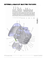
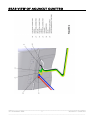
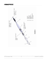
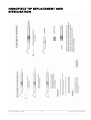
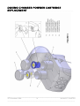
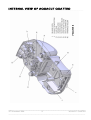
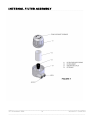
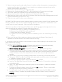
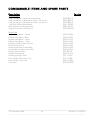
AQUACUT QUATTRO
Fluid
Abrasion
Unit
Installation, Operation
and Maintenance manual
WARNING:
Do not connect to the air supply
before
reading this manual.
CONTENTS
------------------------------------------------------------------------------------------------------------------------------------------------------------------------------------------------------------------------------------------------------------------------------------------------------------------------------------------------------
PAGE
TABLE OF SYMBOLS
2
TECHNICAL DESCRIPTION
3
INDICATIONS FOR USE AND WARNINGS
6
RECOMMENDED ACCESSORIES
7
CONTENTS OF THE PACKAGING
8
EXTERNAL AQUACUT QUATTRO FEATURES
9
REAR VIEW OF AQUACUT QUATTRO
10
HANDPIECE
11
HANDPIECE TIP REPLACEMENT AND STERILISATION
12
DOSING CHAMBER POWDER CARTRIDGE REPLACEMENT
13
INTERNAL VIEW OF AQUACUT QUATTRO
14
INTERNAL FILTER ASSEMBLY
15
CONTROL BLOCK
16
SITING THE AQUACUT QUATTRO
17
MACHINE INSTALLATION
18
PREPARING TO USE THE AQUACUT QUATTRO FOR THE FIRST TIME
21
REMOVING AND REFITTING THE DOSING CHAMBER LIDS
23
_____________________________________________________________________________________
20th November 2006
1
AQUACUT QUATTRO
____________________________________________________________________________________
REMOVING AND INSERTING A POWDER CARTRIDGE
23
STERILISING THE HANDPIECE
24
REMOVING AND REPLACING A HANDPIECE
25
USING THE AQUACUT
QUATTRO
26
THE FIRST STEPS TO MASTERING THE AQUACUT QUATTRO
27
MAINTENANCE OF THE AQUACUT QUATTRO
30
TROUBLESHOOTING
36
CONSUMABLE ITEMS AND SPARE PARTS
38
NOTES
39
TABLE OF SYMBOLS
------------------------------------------------------------------------------------------------------------------------------------------------------------------------------------------------------------------------------------------------------------------------------------------------------------------------------------------------------
_____________________________________________________________________________________
20th November 2006
2
AQUACUT QUATTRO
____________________________________________________________________________________
_____________________________________________________________________________________
20th November 2006
3
AQUACUT QUATTRO
____________________________________________________________________________________
TECHNICAL DESCRIPTION
------------------------------------------------------------------------------------------------------------------------------------------------------------------------------------------------------------------------------------------------------------------------------------------------------------------------------------------------------
READ THIS MANUAL FULLY BEFORE ATTEMPTING TO
INSTALL OR USE THE AQUACUT QUATTRO MACHINE.
The AQUACUT QUATTRO fluid abrasion unit is a twin dispenser system. This allows the user to
select either Cutting or Polishing Powders instantly. The Dosing Chambers can be loaded with
either 29 or 53 micron aluminium oxide for tooth reduction and fine granular sodium
bicarbonate for tooth cleaning and polishing.
The AQUACUT QUATTRO is entirely pneumatic in operation and therefore the only supply
needed to the machine is a clean, dry air supply of between 5 bar, (72 psi) and 7.5 bar,
(109 psi) to ISO 8571.1 class 1.4.1. This can be the dental practice’s existing air supply
system, an independent compressor or bottled air/nitrogen.
Secondary gas supply is not recommended at this time.
It is essential that a high performance water removing filter and a shut-off valve are fitted in the
supply line, (see section on recommended accessories).
The incoming air to the AQUACUT QUATTRO is internally regulated to 7.5 bar, (109 psi) max,
for the pneumatic control system with and supply to the powder cartridge chambers to 5 bar,
(72 psi).
The flow of clean dry air to the handpiece is initiated by depressing the foot switch roller down
to the first index position. (Felt as 1st resistance point to downward movement).
The flow of clean air and fluid to the handpiece is initiated by depressing the foot switch roller
down to the second index position. (Felt as 2nd resistance point to downward movement).
The flow of powder and fluid to the handpiece is initiated by depressing the foot switch roller
fully down. Residual powder in the line to the handpiece is vented into a filtered exhaust
collector inside the machine when the roller is allowed to return to the upper position.
The foot pedal actuates a purpose built pinch valve block within the Aquacut Quattro, which
in turn controls the flow of the abrasive laden air.
The pinch valve tubes are easily changed on a routine basis in a few minutes without the use
of special tools.
The abrasive powders are supplied in sealed, colour-coded single use cartridges that are
calibrated to supply the correct range of flow rates for each powder.
The powder cartridges can be changed at any time by simply switching the Aquacut Quattro
off, removing the lid from the dosing chamber, lifting out the powder cartridge and sliding in a
new one after removing the two yellow sealing tabs. Replace the dosing chamber lid, switch
on the supply and the unit is ready for use again.
When in use, the dosing chamber lids are held securely in place automatically and cannot be
inadvertently removed while under pressure.
To undo a lid, the Aquacut Quattro must be switched off; this automatically vents the internal
pressure from the complete unit. Residual powders in the lines are filtered into the exhaust
collector.
Complete depressurisation of the machine takes about 20-30 seconds.
The Aquacut Quattro fluid runs in a parallel path to the handpiece tip, where it combines with
the cutting medium. The fluid is drawn up the twin supply tube to the tip by the venturi effect
of the particle air stream. At the tip the fluid is ejected as a conical spray over the outside of the
particle stream and acts to contain the cutting medium within the cutting area. In this way the
amount of airborne Aluminium Powder/Sodium Bicarbonate is significantly reduced.
_____________________________________________________________________________________
20th November 2006
4
AQUACUT QUATTRO
____________________________________________________________________________________
There are four controls available to the user, the Air/2nd supply selector; Cut/Polish Powder
selector; Powder volume and Cutting/Polishing speed.
The air pressure, (Speed), at the handpiece can be adjusted over a variable range of 1 – 3.
The Powder volume can be adjusted over a variable range of 1 – 5.
The handpiece with fitted tungsten carbide tipped nozzles is easily removed from the air line
for cleaning, sterilizing or replacement.
WARNING: WHEN OPERATING THE AQUACUT QUATTRO, IT IS
ESSENTIAL THAT A FILTERED HIGH SPEED INTRA-ORAL EVACUATION
UNIT IS USED AT ALL TIMES.
IT IS ALSO RECOMMENDED THAT A FILTERED EXTRA-ORAL
EVACUATOR IS ALSO USED.
_____________________________________________________________________________________
20th November 2006
5
AQUACUT QUATTRO
____________________________________________________________________________________
The overall dimensions of the AQUACUT QUATTRO: Width
Height
Depth
Nett weight
250mm [9.8 Inches)
240mm [9.4 inches)
230mm (9.1 inches)
7.5kgs (16.5 lbs)
The AQUACUT QUATTRO is a class lla medical device.
TYPICAL CUTTING PERFORMANCE THROUGH 1mm OF GLASS.
0.5mm Dia nozzle, 29 micron aluminium oxide.
3 bar cutting pressure, Low vibrator pressure: 10 seconds.
7 bar cutting pressure, High vibrator pressure: 5 seconds.
0.6mm Dia nozzle, 53 micron aluminium oxide.
3 bar cutting pressure, Low vibrator pressure: 6 seconds.
7 bar cutting pressure, High vibrator pressure: 2 seconds.
0.8mm Dia nozzle, 53 micron aluminium oxide.
3 bar cutting pressure. Low vibrator pressure: 3 seconds
7 bar cutting pressure, High vibrator pressure: 1.5 seconds
ENVIRONMENTAL CONDITIONS FOR TRANSPORT AND STORAGE
The AQUACUT QUATTRO should be kept within the Temperature range -10°C and +40°C
(14°F and 104°F) and below 80% humidity.
_____________________________________________________________________________________
20th November 2006
6
AQUACUT QUATTRO
____________________________________________________________________________________
INDICATIONS FOR USE AND WARNINGS
------------------------------------------------------------------------------------------------------------------------------------------------------------------------------------------------------------------------------------------------------------------------------------------------------------------------------------------------------
INDICATIONS FOR USE
Preparation for Pit and Fissure Sealants
Removal of Composites for Restoration
Cavity Preparation
Cleaning, Polishing and Stain removal
Etching
WARNINGS
Do not turn on the air supply until you have read the complete manual, particularly the section
headed ‘Removing and Refitting the Dosing chamber lids’ (see page 21), and have made sure
that both Dosing Chamber Lids, (item 14 & 16), are correctly and fully engaged.
All powders supplied by Velopex are sterile until opened and containers are not reusable.
The foot pedal, (item 11), must be sited in such a place that it will not be operated by accident
as this will cause a high pressure stream of abrasive powder to be emitted from the cutting
nozzle, (item 31), in an uncontrolled and therefore dangerous manner.
Use only original Medivance consumable products, (powders etc), as other makes may
damage or alter the performance of the Aquacut Quattro and make the machine dangerous.
Always ensure safety goggles and everyone in the area when setting up or
using this equipment wears respiratory masks.
Always ensure the handpiece is under control and the nozzle is pointing in a safe direction.
Handpieces MUST be sterilised before first use and between patient treatments.
Disposable feedline and tips are for one time use only. Always use a new feedline and tip
with each patient.
RECOMMENDED ACCESSORIES
------------------------------------------------------------------------------------------------------------------------------------------------------------------------------------------------------------------------------------------------------------------------------------------------------------------------------------------------------
WARNING: ALL REPLACEMENT PARTS AND CONSUMABLES MUST BE
SOURCED FROM MEDIVANCE INSTRUMENTS TO ENSURE CORRECT
AND
SAFE FUNCTIONING OF THE AQUACUT - REFER TO PAGE 33 FOR
DETAILS
The following parts are available for the preparation of the Aquacut Quattro air supply
_____________________________________________________________________________________
20th November 2006
7
AQUACUT QUATTRO
____________________________________________________________________________________
Breathing air filter unit
Shut off tap
Pressure regulator
Filter Regulator Tip
6mm Hose
4mm Hose
6mm to 4mm Converter
‘Quick Release Fittings’
Replacement Upper Cartridge for Breathing Air Filter
Replacement Lower Cartridge for Breathing Air Filter
Quick release Twin feed tube assembly
I/FIT 8200P
I/FIT 820IP
I/FIT 8202P
_____________________________________________________________________________________
20th November 2006
8
AQUACUT QUATTRO
____________________________________________________________________________________
CONTENTS OF THE PACKAGING
------------------------------------------------------------------------------------------------------------------------------------------------------------------------------------------------------------------------------------------------------------------------------------------------------------------------------------------------------
1.
1 off
Aquacut Quattro fluid abrasion unit.
2.
1 off
Three-position Foot pedal.
3.
1 off
0.6mm Handpiece (Colour Silver).
4.
1 off
Quick release Twin feed tube assembly.
5.
2 off
Cartridge of gamma irradiated aluminium oxide, 53 micron, (Red).
6.
2 off
Cartridge of gamma irradiated aluminium oxide. 29 micron, (Blue).
7.
2 off
Cartridge of gamma irradiated fine granular sodium bicarbonate (Clear).
8.
1 off
Operation manual.
9.
1. off
User manual.
10.
1 off
Pack 5 Glass slides.
11.
1 off
Nozzle cleaning wire.
12.
1 off
2 metre length 4mm air input hose.
13.
1 off
500ml Bottle fluid.
14.
1 off
Pack 50 disposable feed line and tips.
15.
1 off
Powder storage pot.
16.
1 off
20ml syringe for handpiece flushing.
_____________________________________________________________________________________
20th November 2006
9
AQUACUT QUATTRO
____________________________________________________________________________________
EXTERNAL AQUACUT QUATTRO FEATURES
------------------------------------------------------------------------------------------------------------------------------------------------------------------------------------------------------------------------------------------------------------------------------------------------------------------------------------------------------
_____________________________________________________________________________________
20th November 2006
10
AQUACUT QUATTRO
____________________________________________________________________________________
REAR VIEW OF AQUACUT QUATTRO
_____________________________________________________________________________________
20th November 2006
11
AQUACUT QUATTRO
____________________________________________________________________________________
HANDPIECE
------------------------------------------------------------------------------------------------------------------------------------------------------------------------------------------------------------------------------------------------------------------------------------------------------------------------------------------------------
_____________________________________________________________________________________
20th November 2006
12
AQUACUT QUATTRO
____________________________________________________________________________________
HANDPIECE TIP REPLACEMENT AND
STERILISATION
------------------------------------------------------------------------------------------------------------------------------------------------------------------------------------------------------------------------------------------------------------------------------------------------------------------------------------------------------
_____________________________________________________________________________________
20th November 2006
13
AQUACUT QUATTRO
____________________________________________________________________________________
DOSING CHAMBER POWDER CARTRIDGE
REPLACEMENT
------------------------------------------------------------------------------------------------------------------------------------------------------------------------------------------------------------------------------------------------------------------------------------------------------------------------------------------------------
_____________________________________________________________________________________
20th November 2006
14
AQUACUT QUATTRO
____________________________________________________________________________________
INTERNAL VIEW OF AQUACUT QUATTRO
------------------------------------------------------------------------------------------------------------------------------------------------------------------------------------------------------------------------------------------------------------------------------------------------------------------------------------------------------
_____________________________________________________________________________________
20th November 2006
15
AQUACUT QUATTRO
____________________________________________________________________________________
INTERNAL FILTER ASSEMBLY
------------------------------------------------------------------------------------------------------------------------------------------------------------------------------------------------------------------------------------------------------------------------------------------------------------------------------------------------------
_____________________________________________________________________________________
20th November 2006
16
AQUACUT QUATTRO
____________________________________________________________________________________
CONTROL BLOCK
------------------------------------------------------------------------------------------------------------------------------------------------------------------------------------------------------------------------------------------------------------------------------------------------------------------------------------------------------
_____________________________________________________________________________________
20th November 2006
17
AQUACUT QUATTRO
____________________________________________________________________________________
SITING THE AQUACUT QUATTRO
------------------------------------------------------------------------------------------------------------------------------------------------------------------------------------------------------------------------------------------------------------------------------------------------------------------------------------------------------
Familiarise yourself with the layout of the AQUACUT QUATTRO by referring to the illustrations
within this manual.
The machine is designed to be used on a rigid table top or on a purpose built dental cart with
the controls in easy reach of the Dentist.
Do not place the machine close to the edge or allow overhanging of the table top.
NOTE: Consideration must be given to the fact that the AQUACUT QUATTRO uses light
vibration to dispense the abrasive powder and any lack of rigidity of the table or work surface
will adversely affect the maximum flow rate of the powder.
Site the foot pedal, (item 11), within easy reach of the Dentist and route the hose to the rear of
the machine.
_____________________________________________________________________________________
20th November 2006
18
AQUACUT QUATTRO
____________________________________________________________________________________
MACHINE INSTALLATION
------------------------------------------------------------------------------------------------------------------------------------------------------------------------------------------------------------------------------------------------------------------------------------------------------------------------------------------------------
Before proceeding to install the Aquacut Quattro, ensure the air supply is available and meets
the site requirements detailed on page 2 and in the section Technical Description on page 3.
Always ensure safety goggles are worn by everyone in the area when
setting up or using this equipment.
Always ensure the handpiece is under control and the nozzle is
pointing in a safe direction.
Do not turn on the air supply until you have read the complete
manual, particularly the section headed ‘Removing and Refitting the
Dosing Chamber Lids’, and made sure that both lids, (item 14 & 16),
are correctly and fully engaged.
To prevent unnecessary use of powder, only fit the powder cartridges when required.
Refer to Figures 1; 2; 3; 4; 5 & 6 during the installation process.
1. Remove the machine from the box and place it onto the working surface.
2. Connect the foot valve to the back of the machine by pushing each coloured tube fully
into the four corresponding colour coded connectors, (items 20 - 25). (To disconnect,
first push the coloured connector collet inwards and hold, then push the tube inwards
and then pull out).
3. Connect the 4mm Blue supply line from the air supply outlet to the air inlet of the
machine, (item 24).
4. Red supply line connection for Secondary Gas supply outlet to the machine, (item 25).
(NOT RECOMMENDED AT THIS TIME).
5. By pressing lightly down on the top of the machine, pull the Release Catch, (item 5),
and allow the front of the machine to open. Slide out the Fluid Tank, (item 19), from the
machine and fill with Cutting Fluid. Replace the Tank Lid and slide back into position.
Press down on top of the machine until the Release Catch operates to hold the front of
the machine down securely.
6. Unpack the Quick Connect Twin Tube Line, (item 26). Connect one end, (marked with
a black sleeve), to the outlets of the machine, (item 6 & 7),
7. Unpack and connect a 0.6mm nozzle Handpiece to the other end of the twin tube.
Slide the handle, (item 27), onto the twin tube, (item 26) then firmly push the two tubes
onto the Hand Grip, (item 29), until they are fully located. Then slide the handle back
onto the Hand Grip until it ‘clicks’ into position.
Handpiece sizes are as follows: - Blue
= 0.5mm
(Optional extra)
Silver
= 0.6mm
(Supplied)
Gold
= 0.8mm
(Optional extra)
NOTE: - The nozzle, (item 31), and Hand Grip, (item 29), are
permanently connected and should not be separated. To change
the nozzle cutting sizes simply change the complete handpiece.
8. Assemble a replaceable feed line and tip, (item 30), to the nozzle ensuring that it is firmly
pressed on and square, (see Figure 4). Push the tube into the Handpiece connector
underneath the nozzle.
9. Check the Dosing Chamber Lids, (item 14 & 16), are correctly fitted. See page 21.
10. Wear safety goggles. Turn on the air supply to the machine, (item1), by selecting
the appropriate gas setting, (I = Air; II = Secondary gas – not recommended at this time).
_____________________________________________________________________________________
20th November 2006
19
AQUACUT QUATTRO
____________________________________________________________________________________
Rotate the 2 lower rotary control knobs from high to low setting, then set the speed
control to 1, (centre position) and the Powder control to 2, (centre position).
11. Pick up the Handpiece and pointing nozzle into a safe/suitable place, (sink/bin/aspirator
etc). Press down onto the WASH position of the foot pedal to operate the machine.
Check after a few seconds that fluid is being drawn up the fluid tube. Continue to
operate until the fluid sprays a fine mist from the nozzle.
12. Release the DRY position of the foot pedal to check that air continues but fluid stops.
13. Press the foot pedal fully down, (CUT), to check that the vibrators work and fluid flows.
(Rotate the Powder Selector Switch, (item 3), to check that the other pot vibrates).
14. Mode of operation for the foot control is as follows: CUT
- Fully Down Position
- Vibration-Powder- Fluid
WASH
- Middle Position
- Fluid- Clean air
DRY
- Upper Position
- Dry clean air
15. Switch off the machine using the rotary off switch, (item 1).
16. Wait – The machine will take approximately 20 SECONDS to depressurise before the
Dosing Chamber Lids can be unscrewed and removed.
17. The following instructions cover the insertion of a new powder cartridge into a dosing
chamber for the first time. On any subsequent occasion refer to the section headed
REMOVING AND INSERTING A POWDER CARTRIDGE.
18. ENSURE THE APPROPRIATE POWDER IS INSERTED INTO THE CORRECT CHAMBER AS
FOLLOWS:
Powder Type
Colour Code
Position
SODIUM BICARBONATE
WHITE
LEFT HAND
ALUMINIUM OXIDE (29 or 53 micron)
RED/BLUE
RIGHT HAND
19. Refer to Figure 5. Take a Clear, (white- sodium bicarbonate) powder cartridge for
insertion into the Left Hand Chamber. Remove the lower yellow draw tab ‘A’.
Position the cartridge over the dosing chamber, (item 13), ensuring that the flat on the
cartridge matches the dosing chamber. Insert the cartridge ensuring the rib slides down
the slot inside the Dosing Chamber. The upper flange should rest on the top face of the
chamber. Remove the upper yellow top seal ‘B’. Replace the dosing chamber
lid tightly. The black marker line should face forward.
20. Repeat the procedure to insert the required cutting powder in the Right Hand
Chamber, (Item 17), Red/Blue.
21. Aim the handpiece into the aspirator and turn on the Air Supply to position I, (item 1).
Press the foot pedal to ‘CUT’ position and check the machine is operating and powder is
flowing. Recheck the three Foot pedal operation modes, (see 14 above).
22. Test;- Aim the handpiece at about 25-30mm from a piece of tissue paper and press
‘CUT’ on foot pedal. Check that a ring of white powder inside an outer ring of fluid can
be seen. This is best carried out in a sink area to help contain the powder.
23. A secondary Gas supply is connected, (NOT RECOMMENDED AT THIS TIME),
select II, (item1) and repeat the test in 22 above.
24. The machine is now set up for use. Turn off machine. Remove handpiece.
PREPARING TO USE THE AQUACUT QUATTRO FOR
THE FIRST TIME
-----------------------------------------------------------------------------------------------------------------------------------------------------------------------------------------------------------------------------------------------------------------------------------------------------------------------------------------------------
_____________________________________________________________________________________
20th November 2006
20
AQUACUT QUATTRO
____________________________________________________________________________________
Use only original Medivance consumable products, (i.e. powders etc),
as other makes may damage or alter the performance of the Aquacut
Quattro and make the machine dangerous.
Refer to the USER MANUAL for guidance in selecting the correct
powders.
The Handpieces (item 18) are supplied clean but not sterilised. It is
therefore essential that they are sterilised before use and between
every patient.
Refer to the following sections when preparing the Aquacut Quattro
for first time use:STERILISING THE HANDPIECEPAGE 22
REMOVINGAND REPLACING A HANDPIECEPAGE 22
REMOVING AND REFITTING THE DOSING CHAMBER LIDSPAGE
21
REMOVING AND INSERTING A POWDER CARTRIDGEPAGE 21
Proceed as follows;Check the machine is switched OFF, (item1).
The handpieces, (which are supplied with the cutting nozzles permanently attached), are
designed to be repeatedly autoclaved for their sterilisation.
Refer to the section headed STERILISING THE HANDPIECE in this manual
before use on patients.
Fit the required size of handpiece to the Twin Feed Tube, (item 26).
Refer to the USER MANUAL for guidance in selecting the correct nozzle.
Fit the disposable feed line and tip, (item 30), to the handpiece nozzle.
Fit the required Powder cartridges into the dosing chambers.
Refer to the USER MANUAL for guidance in selecting the correct powder for a particular
procedure.
Fill the Cutting Fluid Tank, (item19).
For the next two settings the AQUACUT QUATTRO will need to be switched on at the on/off
switch, (item 1).
The pressure of the abrasive laden air that will flow from the nozzle can be set by turning the
air pressure control, (item 4), on the front panel and observing the gauge, (item 8).
The air pressure options are:
Area 1 - low energy, gentle action
TO
Area 3 - high energy, very fast cutting.
Refer to the USER MANUAL for guidance in selecting the correct air pressure settings.
The amount of powder entrained in the air flow can be set by turning the flow control, (item
2).
The abrasive content options are:
1
- Low powder content, slow cutting/cleaning,
TO
5
- High powder content, very fast cutting/cleaning.
Refer to the USER MANUAL for guidance in selecting the correct abrasive content.
FLUID SYSTEM
_____________________________________________________________________________________
20th November 2006
21
AQUACUT QUATTRO
____________________________________________________________________________________
The amount of fluid delivered to the cutting nozzle is factory preset. The flow rate is controlled
automatically depending on the selected nozzle size and air pressures.
When re-filling the Fluid Tank, the smaller tube of the twin assembly will need to be purged of
any air that may have entered the system.
To achieve this turn the powder setting to 1, (item 2), this will prevent unnecessary powder
being expelled from the handpiece. Point the handpiece in a safe direction, (i.e. the inlet of the
evacuation unit), and press the foot pedal ‘WASH’ centre position. The machine will expel air
from the handpiece and purge the fluid through the line.
The procedure is complete when a continuous fine mist sprays from the nozzle and no air
pockets can be seen in the smaller tube.
Reset the pressure on the powder setting, (item 2).
We recommend that the Fluid Tank is checked and re-filled daily as a matter of surgery
procedure to prevent running out of fluid whilst working. Depending on usage this may also
be carried out at the beginning of the afternoon session.
The feed line and tip are for one time use only. To prevent cross
contamination always use a new disposable feedline and tip, (item
30), with every patient.
Always flush the fluid through the tube system for 20 seconds before
initial use and at the start of every day.
_____________________________________________________________________________________
20th November 2006
22
AQUACUT QUATTRO
____________________________________________________________________________________
REMOVING AND REFITTING THE DOSING
CHAMBER LIDS
------------------------------------------------------------------------------------------------------------------------------------------------------------------------------------------------------------------------------------------------------------------------------------------------------------------------------------------------------
Ensure that the AQUACUT QUATTRO is turned off, at the on/off selector (item 1).
WARNING: ALWAYS MAKE SURE THAT THE NOZZLE (item 31) IS AIMED
INTO THE INLET OF YOUR EVACUATION UNIT AND THE EVACUATION
UNIT
IS TURNED ON WHILE THE AQUACUT IS BEING TURNED OFF OR ON.
WAIT UNTIL THE AIR HAS BEEN EXHAUSTED FROM THE MACHINE
BEFORE REMOVING THE DOSING CHAMBER LIDS. THE MACHINE WILL
TAKE ABOUT 30 SECONDS TO DEPRESSURISE WHEN TURNED OFF.
To remove the lids (item 14/16), unscrew anticlockwise for ⅔ of a turn at which point you will
feel the pressure seal release. Then unscrew a further 1 turn and lift off. This extra 1 turn is a
safety feature which allows any pressure retained in the dosing chamber to exhaust to air
while the lid is still safely engaged.
To refit the lid, place back on top of the dosing chamber (item 13/17) and screw clockwise
until the seal is felt engaging with the top of the chamber. Continue to screw until the lid
comes against a ‘stop’, this is indicated when the line engraved on the skirt of the lid is facing
to the front of the machine.
ALWAYS ENSURE THE CORRECT COLOUR CODED LID IS FITTED TO THE
CORRESPONDING CHAMBER AS FOLLOWS: White
Left Hand Lid Cleaning Powders
Red or Blue
Right Hand Lid Cutting Powders
REMOVING AND INSERTING A POWDER
CARTRIDGE
--------------------------------------------------------------------------------------------------------------------------------------------------------------------------------------------------------------------------------------------------------------------------------------------------------------------------------------------------------------------------------------------------------------------------
WARNING: ONLY USE ORIGINAL MEDIVANCE POWDERS WHICH ARE
SEALED IN NEW CONTAINERS. OTHER POWDERS COULD ALTER THE
PERFORMANCE OF THE AQUACUT QUATTRO AND MAKE THE
MACHINE DANGEROUS.
To remove a previously used powder cartridge, put a steadying hand on top of the AQUACUT
QUATTRO outer cabinet and gently lift the cartridge out of the dosing chamber.
If the powder cartridge is not empty and is going to be used again later, replace it carefully into
the plastic storage pot supplied with the product.
Refer to Figure 5. To fit a new powder cartridge, take a new powder cartridge of the required
grade and remove the lower yellow draw tab (A).
Position the powder container over the dosing chamber, (item 13/17), ensuring that the flat
on the powder cartridge's skirt is in line with the flat inside the dosing chamber.
Insert the cartridge into the dosing chamber so that the rib on the cartridge slides down the
slot inside the dosing chamber. The powder cartridge will slide fully down until its top flange
rests on the top face of the dosing chamber.
If the powder cartridge will not go fully down, remove and check that the rib on the powder
cartridge skirt slides down the slot in the flat inside the dosing chamber, and try again.
Peel off the upper yellow sealing tab (B).
_____________________________________________________________________________________
20th November 2006
23
AQUACUT QUATTRO
____________________________________________________________________________________
Finally, refit the dosing chamber lid.
ALWAYS ENSURE THE CORRECT COLOUR-CODED LID IS FITTED TO THE
CORRESPONDING CHAMBER AS FOLLOWS: White
Left Hand Lid
Cleaning Powders
Red or Blue
Right Hand Lid
Cutting Powders
STERILIZING THE HANDPIECE
------------------------------------------------------------------------------------------------------------------------------------------------------------------------------------------------------------------------------------------------------------------------------------------------------------------------------------------------------
The handpiece has been designed for reprocessing using a steam sterilizer.
The handpieces are supplied clean but not sterile, therefore it is essential that they are
sterilized before first being used and between patients.
Before sterilizing, the handpieces should be thoroughly washed in mild soapy water, cleaned
and rinsed to remove any debris. An ultrasonic cleaning bath can also be used.
To ensure satisfactory steam penetration during sterilization, it is important to check that the
two channels through the handpiece are clear and unblocked. To test this, fill the special
syringe supplied with clean water and, by holding the end firmly against each channel in turn,
squirt water through the handpiece and check for flow from the nozzles.
If the nozzle is blocked use the cleaning wire supplied to remove the debris.
The syringe should also be used for general flushing and cleaning of the handpiece channels.
THE HANDPIECE MUST BE STERILIZED BETWEEN USES TO THE
FOLLOWING CONDITIONS:–
Minimum 134˚C, (273˚F) at 2 bar for 3.5 minutes. This will ensure that a Sterility Assurance
Level (SAL), of 1 X 10¯6 is achieved.
A suitable sterilization pouch should be used to maintain sterility and used in accordance with
the manufacturer’s instructions.
REMOVING AND REPLACING A HANDPIECE
--------------------------------------------------------------------------------------------------------------------------------------------------------------------------------------------------------------------------------------------------------------------------------------------------------------------------------------------------------------------------------------------------------------------------
WARNING: Do not use a handpiece if the hole in the tip of the nozzle
is worn to the outer edge or if the swan neck tube is perforated by the
abrasive.
WARNING: Use only handpieces supplied by Medivance Instruments as
other makes may damage or alter performance and make the machine
dangerous.
Refer to Figures 3 & 4
To remove the disposable feed line and tip, (item 30), pull the feedline off the lower handle
connector. Pull the plastic tip off the cutting nozzle.
To remove the handpiece, (item 18), from the Twin Tube, (item 26), pull the Hand Grip (item
29), and Handle (item 27), apart. Pull the Twin Tube out of the Collet Lock (item 28), until the
two parts come free.
To fit a new handpiece, slide the handle (item 27), onto the twin tube (item 26) then firmly
push the two tubes onto the Hand Grip (item 29), until they are full located. Then slide the
handle back onto the Hand Grip until it ‘clicks’ into position.
To fit the disposable feed line and tip (item 30), first fold over the 'O' ring locking tab of the
plastic tip and push squarely onto the Hand Grip (item 29), until firmly engaged.
Rotate the tip so that the feed line is positioned centrally underneath the nozzle.
_____________________________________________________________________________________
20th November 2006
24
AQUACUT QUATTRO
____________________________________________________________________________________
Finally, push the feed line onto the connector.
The feed line and tip are for one time use only. To prevent cross
contamination always use a new disposable feedline and tip (item 30),
with each patient.
Always flush the fluid through the tube system for 20 seconds before
initial use and at the start of every day.
_____________________________________________________________________________________
20th November 2006
25
AQUACUT QUATTRO
____________________________________________________________________________________
USING THE AQUACUT QUATTRO
------------------------------------------------------------------------------------------------------------------------------------------------------------------------------------------------------------------------------------------------------------------------------------------------------------------------------------------------------
ATTENTION- Please read all the following important warnings before using the Aquacut
Quattro:
Only qualified dentists and dental hygienists should use the Aquacut Quattro on patients,
after reading this manual fully.
Before using the Aquacut Quattro, the person operating the unit, any assistants, the patient
and anyone else in the room must wear eye protection to BS EN 166 IF 4/5
and, except for the patient, they must all wear respiratory masks to EN 149
FF2S.
The disposable tip and feed tube are for one time use only and must be changed for each
patient.
The handpiece must always be autoclaved (sterilised) between patients.
Patients who are on restricted sodium diets or have respiratory problems should consult
their physicians before having treatment with Aquacut Quattro.
Aquacut Quattro may cause soft tissue damage, including inflammation and bleeding, and
creation of an air embolism.
Aquacut may cause hard tissue damage including etching or abrasion of enamel or
exposed root surfaces of the teeth.
When switching powders, (especially from Aluminium Oxide to Sodium
Bicarbonate), the powder line must be purged by pressing the ‘CUT’ (bottom) position of
the foot pedal for 10 seconds minimum. Aim the handpiece nozzle into the aspirator
system to contain the powder.
Before operating the Aquacut Quattro you must be in full control of the handpiece, (item
18) and be pointing the nozzle (item 31), in a safe direction.
In the following circumstances the powder lines and handpiece must be purged of any
previously used powder.
a) each time the AQUACUT QUATTRO is switched on;
b) each time a new cartridge of abrasive powder is loaded into the dosing chamber;
c) each time a cartridge of abrasive powder is replaced with another grade, even if the
replacement powder cartridge has been used before;
d) each time a cartridge of abrasive powder is replaced with the same grade even if the
replacement powder cartridge has been used before;
e) each time you change between the two dosing chambers using the powder
selector control (item 3) on the front panel;
f) each time the air pressure is adjusted, (item 4) on the front panel;
g) each time the abrasive powder flow is adjusted, (item 2) on the front panel;
h) each time a handpiece is replaced.
To purge the feed tube and handpiece of any previously used powder and charge with the
new powder, hold the handpiece and direct the nozzle into the inlet of the evacuation unit
which must be turned on.
Now press the ‘CUT’ (bottom) position of the foot pedal (item 11), for 10 seconds minimum
and observe the flow of abrasive powder as it is emitted from the nozzle. This will not only
charge the feed tube and handpiece with the new abrasive powder and flush out any
previous powder, it will also allow you to see how the powder will look as it comes out of the
nozzle.
_____________________________________________________________________________________
20th November 2006
26
AQUACUT QUATTRO
____________________________________________________________________________________
FIRST STEPS TO MASTERING THE AQUACUT
QUATTRO
------------------------------------------------------------------------------------------------------------------------------------------------------------------------------------------------------------------------------------------------------------------------------------------------------------------------------------------------------
NOTE: Should the Aquacut Quattro cease to operate correctly, or its
performance deteriorate, or it becomes difficult to control, refer to the
trouble shooting guide at the back of this manual.
WARNING: If the Aquacut Quattro is dropped or otherwise damaged, it
must not be used until a service engineer has inspected the unit.
WARNING: The feed line and tip are for one time use only. To prevent
cross contamination, always use a new feed line and tip (item 30),
with each patient.
WARNING: For this section it is important to use high speed
evacuation close to the cutting nozzle (item 31), while following the
procedures below. All persons in the area must wear eye protection to
BS 166 1F 4/5 and respiratory masks to EN149 FFP2S.
Aquacut Quattro tips are designed for use only with the Medivance
Aquacut Quattro. Attempts to use with any other micro abrasion
machines could be hazardous. When fitting a new tip, ensure that it is
firmly engaged on the cutting nozzle.
In most cases wear on the plastic tip should last long enough for one
treatment. However, in the case of prolonged treatment the fluid flow
through the nozzle may reduce and become uncontrolled. If this
occurs, replace with a second tip.
In the pack that comes with the machine are some 1mm thick glass microscope slides that
show a close similarity in hardness to tooth enamel. Cutting through these slides with various
combinations of abrasive powder grade, air pressure, abrasive flow and nozzle diameter will
give you a graphic display of the speed of penetration and the size and shape of the cuts that
are available before you progress to cutting teeth.
Refer to the USER MANUAL and read it thoroughly before proceeding to cut the glass slides or
extracted teeth.
To start, choose settings that cover a typical procedure that you would want to use on a
patient.
NOTE: Confirm the grade of the powder selected, by observing the
colour of the powder container in the selected dosing chamber.
Red =
53 micron aluminium oxide.
Blue =
29 micron aluminium oxide.
Clear/White =
Sodium Bicarbonate.
Handpiece sizes are as follows: Blue =
0.5mm
(Optional extra)
Silver =
0.6mm
(Supplied)
Gold =
0.8mm
(Optional extra)
_____________________________________________________________________________________
20th November 2006
27
AQUACUT QUATTRO
____________________________________________________________________________________
With the Aquacut turned on and all the settings made, switch on your aspirator and hold the
glass slide in front of its inlet tube.
Hold the handpiece with the cutting nozzle, (item 31) facing the glass slide and 1.5mm from its
surface.
Press the foot switch to operate the Aquacut Quattro.
The foot switch has three control positions depending on the area that is pressed. The modes
of operation are as follows:Position
Operation
Action
Fully down Fluid cutting Powder and fluid are supplied from the handpiece
Middle
Wash
Clean air and fluid are supplied from the handpiece
Upper Dry
Clean dry air is supplied from the handpiece
Practise moving your foot through the cut/wash/dry positions, so that you gain confidence
and experience with the way the foot switch operates.
It is important to observe how the abrasive rebounds from the cut surface. Practice moving the
aspirator inlet tube as the handpiece moves so that waste materials are efficiently collected.
Important: - The inside mouth area is much more enclosed than the open work surface.
The result is in a greatly reduced spread of abrasive material in the normal working area.
Try cuts of about 2 seconds duration and observe the results. Repeat the cut with the nozzle at
varying angles to the surface of the glass slide until you feel confident that you can predict the
results and aspirate effectively.
Move the cutting tip backwards and forwards over the area to be cut to examine various
cutting methods and results. Practise using all three cutting media to evaluate the differing
performance and results.
The next step is to practise cutting into an extracted tooth. In the same way modify the various
settings in the light of the results you achieved on the glass slides, until you are satisfied with
the results.
Finally, refer to the USER MANUAL - read it thoroughly again before selecting the various
settings suggested for the procedure you wish to perform and before using the AQUACUT
QUATTRO on a patient for the first time.
WARNING: Special consideration must be given to the use of the
Aquacut Quattro on patients who have:
1. RESPIRATORY DIFFICULTIES
2. ASTHMA
3. A COLD
4. BLOCKED NASAL PASSAGES
5. RESTRICTED SODIUM DIET
6. ANY OTHER MEDICAL PROBLEM THAT MAY PREVENT THE
PATIENT
FROM BREATHING THROUGH THE NOSE.
ANY PATIENT SUFFERING FROM ANY OF THE ABOVE CONDITIONS
SHOULD CONTACT THEIR PHYSICIAN BEFORE HAVING TREATMENT
WITH AQUACUT QUATTRO.
_____________________________________________________________________________________
20th November 2006
28
AQUACUT QUATTRO
____________________________________________________________________________________
MAINTENANCE OF THE AQUACUT QUATTRO
------------------------------------------------------------------------------------------------------------------------------------------------------------------------------------------------------------------------------------------------------------------------------------------------------------------------------------------------------
WARNING: - Always make sure that the nozzle (item 31), is aimed into
the inlet of your evacuation unit and the evacuation unit is turned on
while the Aquacut Quattro is being turned ‘on’ (l or II) or ‘off’’ (O), at
the selector switch (item 1).
Wait until the air has been exhausted from the machine before
carrying out any cleaning or maintenance on the machine.
Always ensure safety goggles are worn by everyone in the area when
setting up, testing or using this equipment.
Always ensure the handpiece is under control and the nozzle is
pointing in a safe direction.
ANNUAL SERVICE AND SAFETY CHECK.
For the continuing safe and reliable functioning of the AQUACUT QUATTRO it is
recommended that you contact your supplier or Medivance Instruments and book an annual
service and safety check.
Ensure the twin tube assembly is replaced annually or when damaged.
This will take only a short time and ensure the continued integrity of your AQUACUT
QUATTRO.
CLEANING THE AQUACUT QUATTRO.
Keep the casing, the dosing chambers, (item 13/17) and their lids (item 14/16) clean with a
pure water dampened cloth, taking care not to allow any liquid to get inside the machine. Use
only mild soapy water for cleaning the case and dosing chambers.
The inside of the dosing chambers, lids and the powder cartridges must be kept dry at all
times.
INSPECTION OF THE DOSING CHAMBERS.
WARNING: under no circumstances must any other cleaning agent,
including surface wipes containing alcohol, come into contact with
the case or the dosing chambers.
The dosing chambers are polycarbonate pressure vessels and must be
inspected for any visible damage each time a new container of
abrasive powder is loaded into them.
If any damage is evident the Aquacut Quattro should not be used until
a Medivance approved service engineer has inspected the machine.
_____________________________________________________________________________________
20th November 2006
29
AQUACUT QUATTRO
____________________________________________________________________________________
EMPTYING AND CLEANING THE FILTERED EXHAUST COLLECTOR.
At the beginning of each day it is necessary to empty the powder exhaust tank (item 9) and
clean the filter (item 38).
Press lightly down on the top of the machine, pull the Release Catch (item 5), and allow the
front of the machine to open. Supporting the machine, pivot the upper part of the machine
fully over and until the cover (item 15), rests on the work surface and the inside is presented as
shown in figure 6. Slide the Powder Tank (item 9), out of position, remove the lid and empty
the contents into a waste bin. DO NOT RE-USE as the powder is contaminated with
cutting/polishing. Replace the tank lid and slide back into position.
Remove the filter pad from the filter, (item38), shake to clean and refit.
Refill the Fluid Tank.
Pivot over the top of the machine and press down until the Release Catch (item 5), operates to
hold the front of the machine down securely.
HANDPIECE.
Cleaning
Handpieces must be cleaned and STERILIZED before first use and
between every patient. See the separate section STERILIZING THE
HANDPIECE on page 22.
Blockages
If the abrasive powder ceases to flow from the nozzle (item 31) while cutting is in progress, the
nozzle may have become blocked with abrasive particles.
Release the foot pedal (item 11), as soon as a blockage is suspected to minimise the amount of
powder collecting behind the nozzle.
Aim the nozzle (item 30), into the inlet of your evacuation unit and make sure the evacuation
unit is turned on while you turn the AQUACUT ‘off’ at the on/off selector, (item 1).
Wait for the air to be exhausted from the machine (about 20 seconds) before proceeding.
Now remove the handpiece and clear the blockage by inserting a length of 0.35mm wire
(supplied) through the nozzle from the tip. Stubborn blockages may be loosened by
immersion in an ultrasonic cleaning bath.
Inspection
Regularly inspect the cutting nozzle and handpiece for excessive wear or damage.
Do not use a Handpiece if the hole in the tip of the nozzle is worn to the outer edge or if the
abrasive perforates the swan neck tube.
TWIN TUBE ASSEMBLY
Cleaning
The Twin Tube Assembly (item 26), must not be autoclaved.
Wash the Twin Tube Assembly in mild soapy water and rinse thoroughly. Allow to dry
completely before use.
Always purge the tubes with Powder and Fluid thoroughly before use.
Inspection
Ensure the Twin Tubes are in good condition and fit together correctly with the Handpiece.
Test the Check Valve (item 33) is functioning. The valve prevents fluid being forced back down
the tube during use.
_____________________________________________________________________________________
20th November 2006
30
AQUACUT QUATTRO
____________________________________________________________________________________
Check 1 - With the twin tube filled with fluid, disconnect the tube at the Fluid Out connection,
(item 7). Hold the handpiece up vertically and check that the fluid in the tube does not drip
from the disconnected end. Reconnect the tube.
Check 2 – With the machine in the ‘ready to use’ condition, press the ‘Wash’ control on the
foot pedal and gently press the plastic tip on the end of the nozzle down onto a flat surface
(e.g. a glass slide). The fluid should be prevented from blowing back down the fluid line past
the handpiece. The joint between the plastic tip and feedline may also disconnect.
Replace the whole Twin Tube Assembly if any faults are found.
REPLACING THE ABRASIVE TUBE ASSEMBLY AND INTERNAL FILTERS.
The Aquacut Quattro uses a system of pinched tubes (items 43, 44, 45 & 46), to control the
abrasive powders supplying the handpiece. Over time, these wear and should be replaced
every 12 months.
If the Aquacut Quattro exhibits an audible air leak from inside the machine and performance
falls below standard, it is possible that one of these abrasive tubes has split near one of the
pinch valves.
The Aquacut Quattro also has 2 internal air filters (items 35), that protect critical components.
These should be visually inspected at the same time and if necessary replaced.
The Aquacut Quattro has been designed so that these tubes and filters can be easily replaced
without the need for specialist tools. The procedure should take no longer than 15 minutes.
For spare parts you will need to specify the machine Serial Number shown on the technical
label on the back of the machine.
You will need both a medium size flat and a cross head screwdriver.
WARNING: Turn off the air supply at the wall outlet and disconnect
the air and Secondary Gas supply inlet connections, (item 24 & 25), at
the rear of the machine before attempting any maintenance.
The abrasive tubes are connected inside
the machine using collet lock fittings.
To disconnect the tube from this type of
fitting proceed as follows and refer to
the diagram opposite.
1. Push and hold the tube towards the fitting.
2. Push in and hold the fitting collar.
3. Pull the tube out of the fitting.
To reassemble, simply push the tube firmly into
the
fitting.
To replace the pinch tubes proceed as follows:Refer to Figure 8.
1. Press lightly down on the top of the machine, pull the Release Catch (item 5), and allow the
front of the machine to open. Supporting the machine, pivot the upper part of the machine
fully over and until the cover, (item 15), rests on the work surface and the inside is
presented as shown in figure 6.
2. Locate the Pinch Block (item 49) and Pinch valves (items 42, 43, 44, & 45).
_____________________________________________________________________________________
20th November 2006
31
AQUACUT QUATTRO
____________________________________________________________________________________
3. Notice that each pinch valve and tube end is colour-coded showing the corresponding
position and location of the parts. Ensure that the new replacement parts have similar
colour coding before proceeding.
4. Remove the 4 small retaining ‘O’-rings (item 42).
5. Slide out the 4 retaining pins (item 47 & 48). Note that the 2 lower pins are longer.
6. The Pinch Valves are now able to be removed from their seating.
7. Disconnect the ends of the tube and discard 4 old pinch valves and tubes.
8. Matching the colour codes, refit the Pinch valves into their respective seating positions and
replace the Retaining Pins and ‘O’ rings.
9. Push the tube ends into their correct positions.
DOUBLE CHECK that the correct coloured tubing connects to the correct Pinch Cylinders and
Dosing Chamber Pot(s). Incorrectly fitted tubing will cause the machine to malfunction and
could cause the wrong powder to be used at the Handpiece.
Check the condition of the Internal Air Filters (item 35). If they appear heavily soiled or wet,
these should also be replaced. Proceed referring to Figure 7.
a) Remove the cover by rotating CLOCKWISE (item 51).
b) Remove the old Filter Element and discard.
c) Refit a new Filter Element (item 52).
d) Tighten the cover by rotating ANTI-CLOCKWISE, (ensure the Valve Plug is correctly
fitted).
10. Pivot over the top of the machine and press down until the Release Catch (item 5),
operates to hold the front of the machine down securely.
It is important that the machine is now tested to ensure that the piping of the machine has
been carried out correctly.
To Test, proceed as follows:a) Place one cartridge only of Powder into the White (Sodium Bicarbonate),
chamber. (Ensure the Red/Blue Dosing Chamber is empty).
b) Wear Safety Goggles. Switch the machine ‘on’ and check for air leaks.
c) Using the Selector Switch (item 3), switch (select), the White Dosing Chamber and press
‘Cut’ on the Foot Pedal while aiming the nozzle at a piece of tissue paper at a distance
of about 25mm (1 inch). This is best carried out in a sink area to help contain the
powder.
d) Check that a central ring of white powder inside an outer ring of fluid can be seen.
e) Next press ‘WASH’ on the Foot Pedal while aiming the nozzle at a piece of tissue paper
at a distance of about 25mm (1 inch).
f) This time you should observe a ring of fluid with no powder.
g) Switch to the Red/Blue Dosing Chamber, (purge the line for 10 seconds to clear any
residual powder).
h) Press ‘CUT’ while aiming the nozzle at a piece of tissue paper at a distance of about
25mm (1 inch).
i) This time you should observe a ring of fluid with no powder. (There is no powder
cartridge in the selected Dosing Chamber).
j) Turn the machine off and move the powder cartridge so that the Red/Blue (cutting
powder) Dosing Chamber has powder loaded and the White Dosing Chamber is
empty.
_____________________________________________________________________________________
20th November 2006
32
AQUACUT QUATTRO
____________________________________________________________________________________
k) Switch the machine ‘on’.
l) Using the Selector Switch (item 3), switch (select) the Red/Blue Dosing Chamber and
press ‘Cut’ on the Foot Pedal while aiming the nozzle at a piece of tissue paper from a
distance of about 25mm (1 inch).
m) Check that a central ring of white powder inside an outer ring of fluid can be seen.
n) Next press ‘WASH’ on the Foot Pedal while aiming the nozzle at a piece of tissue paper
at a distance of about 25mm (1 inch).
o) This time you should observe a ring of fluid with no powder.
p) Switch to the White Dosing Chamber, (purge the line for 10 seconds to clear any
residual powder).
q) Press ‘CUT’ while aiming the nozzle at a piece of tissue paper at a distance of about
25mm (1 inch).
r) This time you should observe a ring of fluid with no powder. (There is no powder
cartridge in the selected Dosing Chamber).
s) Finally add a Powder Cartridge to the White (Sodium Bicarbonate) Dosing Chamber
and check that the CUT: WASH: DRY functions of the machine work satisfactorily when
each Chamber is selected.
Switch off the machine and fit the required Powders into the Dosing Chambers.
The machine is now ready for use.
_____________________________________________________________________________________
20th November 2006
33
AQUACUT QUATTRO
____________________________________________________________________________________
TROUBLESHOOTING
------------------------------------------------------------------------------------------------------------------------------------------------------------------------------------------------------------------------------------------------------------------------------------------------------------------------------------------------------
Symptom:
The unit does not operate when foot pedal is depressed.
Action:
1. Ensure that the compressed air supply is at the specified pressure, is connected and turned
on.
2. Ensure that the unit is switched on and that the air pressure and powder flow controls are
set to a minimum of `1’ on both of the settings. This should ensure that the unit will start
correctly.
3. Check that the foot pedal hoses have been correctly connected to the back of the
machine.
4. Ensure that the dosing chamber lids have been fully engaged. Incorrect fitting will result in
a significant leakage of air from the dosing chamber. To remedy, turn the unit off and
carefully wipe the inner Lid seal and Dosing Chamber sealing face. Fully screw down the
lids so that the black line on the Lids points directly forwards.
5. Check that the pneumatic system has not been contaminated by wet compressed air.
Should this have occurred it will be necessary to change the airline filters, clean or replace
the airline and acquire the services of a Medivance trained engineer to assess the damage
to the Aquacut Quattro unit.
Symptom:
The vibrator does not operate when the foot pedal is depressed.
Action:
1. Ensure that the compressed air supply is at the specified pressure, is connected and turned
on.
2. Check that the foot pedal is connected correctly and that its free movement is not
prevented by its position or some foreign body.
3. Check that the pneumatic system has not been contaminated by wet compressed air.
Should this have occurred it will be necessary to change the airline filters, clean or replace
the airline and acquire the services of an engineer to assess the damage to the Aquacut
Quattro unit.
Symptom:
No air flow through the nozzle.
Action:
1. Ensure that the compressed air supply is at the specified pressure, is connected and turned
on.
2. Ensure that the air pressure regulator is not set at too low a value - a minimum setting of ‘1’
should give a detectable airflow.
3. Check that the nozzle is not blocked. If blocked remove the handpiece and clear the
blockage with a cleaning wire.
Symptom:
Irregular flow or no flow of cutting fluid to the tip.
Action:
_____________________________________________________________________________________
20th November 2006
34
AQUACUT QUATTRO
____________________________________________________________________________________
1. Worn feed line and tip. In most cases the wear on the plastic tip should last long enough
for a patient treatment. Prolonged treatment may result in premature wear which may
result in reduced or uncontrolled flow. Replace with a second tip.
2. Ensure the plastic tip is firmly engaged on the cutting nozzle.
3. Check the fluid tank is not empty and the tube in the tank is fully submerged.
4. Blockage in the supply line. Check the clear twin tube for evidence of material blocking the
tube.
5. Leaking joint, air bubbles in the feed pipe indicates that air is seeping into a joint. The
leaking point can be identified from the spot where the air appears. Check the joint and
replace part.
NOTE: IF THE FAULT CANNOT BE LOCATED AND REPAIRED BY REFERRING TO THIS
TROUBLESHOOTING GUIDE IT WILL BE NECESSARY TO ACQUIRE THE SERVICES OF A
MEDIVANCE TRAINED ENGINEER FOR A MORE THOROUGH DIAGNOSIS.
_____________________________________________________________________________________
20th November 2006
35
AQUACUT QUATTRO
____________________________________________________________________________________
CONSUMABLE ITEMS AND SPARE PARTS
------------------------------------------------------------------------------------------------------------------------------------------------------------------------------------------------------------------------------------------------------------------------------------------------------------------------------------------------------
Description
Consumables
4 off Containers of sodium bicarbonate
4 off Containers of aluminium oxide - 29 micron
4 off Containers of aluminium oxide - 53 micron
1 off Pack 500ml Fluid Bottles
Glass slides for cutting practice
50 pack Feed line and Tips A2
Part No
I/PDR 8015F
I/PDR 8025F
I/PDR 8035F
I/PAC 8202F
I/MIC 0010P
I/ASS 8007M
Spare Parts
0.4mm Handpiece - Green
0.5mm Handpiece - Blue
0.6mm Handpiece – Silver
0.8mm Handpiece – Gold
Exhaust Powder Tank and Lid
Fluid Tank and Lid
Dosing chamber lid assembly
Foot pedal complete with hose
Nozzle cleaning wire
Powder Storage Jar
Flushing Syringe 20ml
Internal Filter Elements 2 off
Internal Filter Assy 2 off
Twin tube
I/ASS 8189A
I/ASS 8190A
I/ASS 8191A
I/ASS 8192A
I/ASS 8193A
I/ASS 8194A
I/ASS 8195A
I/ASS 8196A
I/FIT 8073P
I/ASS 8197A
I/FIT 8101P
I/FIT 8198P
I/ASS 8198A
I/ASS 8020M
_____________________________________________________________________________________
20th November 2006
36
AQUACUT QUATTRO
____________________________________________________________________________________
NOTES
------------------------------------------------------------------------------------------------------------------------------------------------------------------------------------------------------------------------------------------------------------------------------------------------------------------------------------------------------
_____________________________________________________________________________________
20th November 2006
37
AQUACUT QUATTRO
____________________________________________________________________________________
Medivance – Aquacut Quattro Operating Manual– UK –OM50 – Issue 4
Velopex is a trademark of Medivance Instruments Ltd
20/11/06
Pt No I/LIT2807P