1
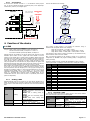
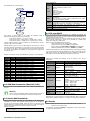
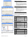
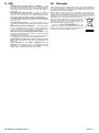
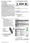
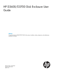
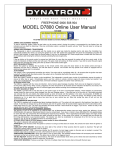
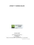
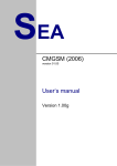
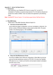
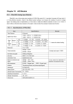
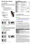
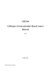
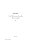
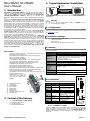
3. Typical Application, Installation FBs-CMGSM, B1-CMGSM User’s Manual GSM Antenna FBs- CMGSM 1. Introduction RS 232 Communication Power + 5 VDC FBs-CMGSM and B1-CMGSM (CMGSM for short) are communication modules for FATEK PLC systems FBs-xxMC and B1-xxM. CMGSM uses the GSM network to transfer the data. CMGSM is based on the quad band GSM module EGS5 Gemalto (850/900/1800/1900 MHz). CMGSM is backed up by 1200 mAh Li-Ion accumulator. CMGSM offer three different ways of communication with connected PLC. The first one is monitoring and remote control of PLC via SMS. CMGSM reads periodically PLC registers containing a flag to send SMS, if the flag is set, CMGSM reads destination phone number and string of characters (text), sends SMS and clears the flag. If there is a SMS received by CMGSM, it is written into PLC registers including another flag “SMS received” to be processed by PLC program. At the end the PLC program clears this flag. So these operational SMS must be processed by PLC program both on SMS reception and SMS sending. Some status and event SMS are predefined in CMGSM (e.g. “Connection to PLC failure”) and only the destination phone number have to be set in PLC registers. The second way of communication with PLC via CMGSM is dial up data transfer via GSM network (CSD). The connection can be only incoming for CMGSM, that may be initiated from a control center for the purpose of remote system analysis and PLC software tuning and modification by WinProladder SW. The third way of CMGSM communication over the GSM network is GPRS data connection using TCP/IP protocol. CMGSM opens the connection in TCP client mode. Any SIM card, that can provide internet connection over the GSM network, can be used. CMGSM connects to IP address and port specified in from PLC. It is important to notice, that the connection can be opened in direction from CMGSM to PC (server) only. PC cannot open a connection to CMGSM because CMGSM has no server implemented and usually does not have public IP address. GPRS has special data transfer properties (data grouping, data transfer delay 1 ... 10 seconds), that are not suitable for WinProladder SW. WinProladder must use dial up data transfer (so called CSD) only. Warning Turn off all power supply during installation of CMGSM to PLC to prevent damage to equipment! 3.1 Configuration If a SIM card does not need PIN code, no configuration for basic use is necessary. For the SIM card with PIN code the configuration in PLC is necessary. Read chapter 5.1 Configuration for more. 3.2 Hardware settings Switch off the power supply of PLC Connect GSM antenna Insert SIM card Connect the flat cable between CMGSM and PLC 3.3 Startup Three ways of GSM network use – SMS, GPRS, Data Call CSD (all of them practically at the same time) WinProladder remote GSM dial up data transfer connection (CSD) USB port for module monitoring Firmware update via GSM available Li-Ion backup 1200 mAh accumulator – min. 24 hours of operation Lowest level super watchdog function (Hardware Power OFF) FBs-CMGSM can be used directly with PLC FBs-xxMC (Port 3) B1-CMGSM can be used directly with PLC B1-xxM One digital input IN and one digital output OUT SMS functionality is fully under PLC program control Configuration of CMGSM means just to set several PLC registers by user No PLC program support is necessary for CSD and GPRS operation LEDs for device status and data flow signalization One CMGSM can work for network of PLC units, inputs and outputs can be placed at different places 1 Unlimited number of logical and 8 analog inputs and outputs can 9 work with one CMGSM (PLC network) 2 Term Description permanently off 600 ms on / 600 ms off No power or STAND BY mode. Device is not logged into the GSM network. This state occurs after start of device for approx. 30 seconds. If it remains, check: SIM card (is inserted?, is valid?) Antenna (is connected?) Configuration (is SIM PIN correct?) Device is logged into the GSM network and is idle. (It means that no GPRS nor CSD connection is active.) 75 ms on / 3 s off 75 ms on / 75 ms off / 75 ms on / 3 s off 500 ms on / 50 ms off permanently on GPRS active, no data GPRS active, data transfer in progress CSD (data connection) in progress Expressed line is common operating state. 3.4 Front Panel 3 + 7 1) 2) 3) 4) 5) 6) 7) 8) 9) GSM antenna connector IO connector SIM card holder USB connector DIN rail holder FUNC button Indication LEDs Flat cable for connection to PLC Indication LEDs 4 6 5 2. Content of the Delivery 1 1 1 1 pc pc pc pc of of of of FAC-FBS-CMGSM or FAC-B1-CMGSM antenna GSM-ANT05S 6 pin connector CD with documentation Name ANT Connector GSM LED blue ERR IO FUNC LED red Connector Button SIM CARD USB SIM card Holder Connector RCV SND LED yellow LED green 3.4.1 Element Description GSM Antenna connector GSM-ANT05S recommended GSM status (see the previous table) Error IN (input), OUT (output) Multifunction Button: DOUT2 change, RESTART, STAND BY mode. Press the SIM card to remove it from holder USB connection to PC for debugging purposes Receiving SMS Sending SMS GSM IN ERR OUT SIM RCV USB 11 Flat cable Note: FATEK PLC is not part of the delivery of this product. It is needed to order independently. Device status is indicated with blue GSM LED on the CMGSM front panel. Valid statuses are as follows: Main features FATEK PLC SND FUNC FBs-CMGSM COMMUNICATION GSM MODULE Pushbutton “FUNC” Pushbutton “FUNC” has several functions. Short press changes the state of the output OUT (DOUT2). Long press (longer than 3 seconds) will either RESTART CMGSM (if CMGSM is powered by the PLC) or enter the STAND BY MODE (if the CMGSM is powered from the internal accumulator - PLC is either disconnected or turned off). FBs-CMGSM User's Manual EN v3-01.doc Page #1 of 7 3.4.1 IO Connector IO connector has 6 terminals. Terminals “+” “-” are intended for service purposes only - for test of an internal accumulator. Terminals IN (“IN1”) are for digital input. Terminals OUT (“DOUT2”) are for digital output. CMGSM *) Please, see the technical specifications for details 50 Ohm 4V How does the CMGSM send a message: START GSM-PWR12 or GSM-PWR1 ? D3800 WRITE 0x0003 INTO D3800 3k9 READ D3810-D3819 Phone number MAX *) 35VAC/70mA 50 VDC/100mA IN 1k WAIT 5s 0x0001 8 to 30 VDC *) TEST ACC. ELSE INPUT (e.g. button or mg. contact) READ D3820-D3899 Text OUT 0,2A SENDING OK ? RESULT ERROR OUTPUT (e.g.relay) GSM-RELE-OUT1 WRITE 0x0000 INTO D3800 WRITE 0x0004 INTO D3800 4. Function of the device 4.1 SMS One of the primary functions of the CMGSM is to send and receive SMS messages. There are 2 kinds of SMS, which have different functions and purposes: SMS for and from PLC FATEK, see chapters 4.1.1. and 4.1.2 Service SMS commands processed by CMGSM, see chapter 4.3 Outgoing SMS from PLC FATEK are sent by PLC program, that writes the text and destination phone number into PLC registers and orders CMGSM to send the message by write special value to another register ( SendFlag). CMGSM sends SMS and writes result of the sending to PLC register (SendFlag). Incoming messages for PLC FATEK are received by CMGSM and the text and origin phone number are written into PLC registers. Subsequently in another register (RecvFlag) is written value, that signalizes new received SMS. PLC program analyzes the registers and deactivates flag RecvFlag. All the SMS structure and security features must be done by PLC program, including confirmation, that SMS was received, if required. SMS messages, which contains characters “#!” (hash and exclamation) followed by access code, are sent and received by CMGSM itself and their function, structure and security features cannot be changed by user or PLC program. Incoming SMS of this kind are described in chapter 4.3 Service SMS Commands and are used to get information about CMGSM status, to reset CMGSM or to get current CMGSM configuration. Outgoing SMS of this kind are described in chapter 4.5 Events. Events, it is information about emergency status of CMGSM module like lost communication with PLC. These events are sent to a predefined phone number (Master in configuration). 4.1.1 Sending a SMS CMGSM periodically tests the first register of the Send Record, standard base is D3800. The Send Record is an area in PLC registers which must be filled by program in PLC in order to send a SMS message. For structure of the record see the following table. Registers Caption Description 0x0000 – Idle 0x0001 – Command to send (written by program in PLC) 0x0003 – SMS is sending (written by D3800 SendFlag CMGSM) 0x0000 – SMS sent successfully (written by CMGSM) 0x0004 – Failed while sending SMS (written by CMGSM) Phone number where to send the D3810-D3819 SendDestAddress message. Length 20 characters. Text of the message. Length 160 D3820-D3899 SendUserData characters. This range of registers can not be used for any other purposes! FBs-CMGSM User's Manual EN v3-01.doc Every register of Phone number or Text contains two characters. String of characters ends with special character 0x00. Examples: String with one character – “A”: D3820 = 0x0041 String “TEXT”: D3820 = 0x4554, D3821 = 0x5458, D3822 = 0x0000 String “HELLO”: D3820 = 0x4548, D3821 = 0x4C4C, D3822 = 0x004F If the length of a phone number is exactly 20 characters (or 160 characters of text) then the character 0x00 at the end is omitted! Base of Send Record (D3800) may be changed to another D or R register via configuration key REGSEND. Only register SendFlag (D3800) is changed during sending a message. Example of sending a message “WE ARE THE CHAMPIONS!” to phone “123465”: (Check register D3800 – SendFlag for value 0x0000 before sending the message!) Register Value Description D3811 0x3231 0x3433 SendDestAddress, characters “1” and “2” SendDestAddress, characters “3” and “4” D3812 0x3635 SendDestAddress, characters “5” and “6” D3813 0x0000 End of string D3820 0x4557 SendUserData, characters “W” and “E” D3821 0x4120 SendUserData, characters “ ” (space) and “A” D3822 0x4552 SendUserData, characters “R” and “E” D3823 0x5420 SendUserData, characters “ ” (space) and “T” D3824 0x4548 SendUserData, characters “H” and “E” D3825 0x4320 SendUserData, characters “ ” (space) and “C” D3826 0x4148 SendUserData, characters “H” and “A” D3827 0x504D SendUserData, characters “M” and “P” D3828 0x4F49 SendUserData, characters “I” and “O” D3829 0x534E SendUserData, characters “N” and “S” D382A 0x0021 SendUserData, characters “!” and end of string D3800 0x0001 SendFlag: send command D3810 4.1.2 Receiving a SMS Incoming SMS messages are saved into registers of PLC in Recv Record, standard base D3700. Structure of the record is in following table. Registers Caption Description 0x0000 – Idle (written by PLC program) D3700 RecvFlag 0x0001 – Message received (written by CMGSM) Phone number of the message sender D3710-D3719 RecvOrigAddress (originator). Length 20 characters. Text of the message. Length 160 D3720-D3799 RecvUserData characters. This range of registers cannot be used for any other purposes! Page #2 of 7 Table of all keywords: Keyword START Message received ON CMGSM: NETWORK=Vodafone CZ 77% IN1=off OUT2=off CSD=no connection GPRS=no connection PLC=connected CMGSM v8.2 Device will respond with confirmation SMS and restart itself. PLC is not affected. This command is used after change of configuration in PLC register to accept the changes by CMGSM. Device will respond with current configuration. (Current configuration is a default configuration with some values changed by configuration string in PLC, see Chapter 5 – Configuration.) CMGSM will respond with confirmation SMS. CMGSM will write default configuration to attached PLC and restart itself. Activate digital output OUT2 OFF Deactivate digital output OUT2 INFO STATE ? D3700 ELSE WAIT 1s 0x0000 WRITE Phone number INTO D3710-D3719 RESET CONFIG WRITE Text of SMS INTO D3720-D3799 FACTORY WRITE 0x0001 INTO D3700 4.4 TCP over GPRS END Every register of Phone number or Text contains two characters. String of characters ends with special character 0x00. Examples: String with one character – “A”: D3720 = 0x0041 String “TEXT”: D3720 = 0x4554, D3721 = 0x5458, D3722 = 0x0000 String “HELLO”: D3720 = 0x4548, D3721 = 0x4C4C, D3722 = 0x004F If length of phone number is exactly 20 characters (or 160 characters of text) the character 0x00 at the end is omitted! CMGSM contains a queue of up to 100 SMS messages. After the queue is full all other SMS messages are discarded. If a power failure occurs all received messages in the queue are lost. Base of Recv Record (D3700) may be changed to another D or R register via configuration key REGRECV. No other registers are changed than the necessary ones. Example of receiving of message “TEST MESSAGE.” from phone “+420123456789”: Register Value One of the primary functions of this device is to establish and maintain TCP connection from PLC to a server. In order to achieve this goal FBsCMGSM has to make following steps after power up: Establish connection to PLC via serial port. Parameters of the serial port are: 9600 baud, 7 data bits, EVEN parity, 1 stop bit, no hw handshake (it is default FATEK settings for all serial ports), address 01h. After power on the FBsCMGSM will proceed steps: Read configuration from PLC register D3900 – D3999. Login to the GSM network, using PIN from configuration. Attach to GPRS, using APN, USER and PASSWD from configuration. Establish and maintain TCP connection to SERVER on port PORT. CMGSM will try indefinitely to read configuration from PLC at the beginning. If there is no serial communication between CMGSM and PLC device will not login into the GSM network! If there is no configuration in PLC or the configuration is damaged or other problem occurs CMGSM writes default configuration into the PLC. Description D3710 0x0001 0x342B RecvFlag: new message RecvOrigAddress, characters “+” and “4” D3711 0x3032 RecvOrigAddress, characters “2” and “0” D3712 0x3231 RecvOrigAddress, characters “1” and “2” D3713 0x3433 RecvOrigAddress, characters “3” and “4” D3714 0x3635 RecvOrigAddress, characters “5” and “6” D3715 0x3837 RecvOrigAddress, characters “7” and “8” D3716 0x0039 RecvOrigAddress, characters “9” and end of string D3720 0x4554 RecvUserData, characters “T” and “E” D3721 0x5453 RecvUserData, characters “S” and “T” D3722 0x4D20 RecvUserData, characters “ ” (space) and “M” D3723 0x5345 RecvUserData, characters “E” and “S” D3724 0x4153 RecvUserData, characters “S” and “A” D3725 0x4547 RecvUserData, characters “G” and “E” D3726 0x002E RecvUserData, characters “.” and end of string D3700 Description Device will respond with SMS describing its current status, e.g. How CMGSM stores a received message: 4.2 GSM Data Connection (Data Call, CSD) Data connection can be established anytime. Even if GPRS communication is in progress. Warning There is no security mechanism against unauthorized data connection to PLC. So it is highly recommended to set security in PLC (password). 4.3 Service SMS Commands Received SMS message with string ‘#!’ and password at the beginning are considered to be service SMS commands. These messages are not forwarded to PLC, but they are processed in CMGSM. Device will check for a valid access code (ACODE parameter in configuration) and if the access code is valid, the message is searched for keywords. Only one keyword in every SMS is executed. Example of this SMS: #!1234 INFO #!998877 CONFIG FBs-CMGSM User's Manual EN v3-01.doc GPRS can be controlled and monitored via set of registers in PLC and via configuration: Registers Caption Description 0=no connection (written by PLC) D3510 GprsCommand 1=open connection (written by PLC) 0x00=no connection, idle 0x01=connecting D3511 GprsState 0x80=connected 0x81=disconnecting D3512 GprsCntErr Error counter for connection Data counter, direction UP D3516-D3517 GprsCntUp (= PLCTCP), D3516 LSB Data counter, direction DOWN D3518-D3519 GprsCntDown (= TCPPLC), D3518 LSB Local IP address if connected. “0.0.0.0” if not connected. (D3520=MSB) Example: If local IP address is 147.32.80.1, then D3520-D3523 GprsLocalIP D3520 … 0x0093 (147d) D3521 … 0x0020 (32d) D3522 … 0x0050 (80d) D3523 … 0x0001 (1d) Local TCP port if connected, 0 if not D3524 GprsLocalPort connected Remote IP address if connected. “0.0.0.0” D3525-D3528 GprsRemoteIP if not connected. (D2425=MSB) Remote TCP port if connected, 0 if not D3529 GprsRemotePort connected This range of registers cannot be used for any other purposes! GPRS diagnostic is part of Diagnostic (see chapter Diagnostic). Base of Diag Record (D3500) may be changed to another D or R register via configuration key REGDIAG. 4.5 Events Device can detect special events and send a warning about them as a SMS: Connection to PLC failure/restore It is needed to set parameter MASTER in configuration for both of these events, see chapter 5.2 Basic Parameters. Page #3 of 7 4.6 Diagnostic Diagnostics values are written to Diagnostic Record, standard base D3500. Structure of the record is in following table: Registers Caption Description 0=no connection to PLC, 1=connection to D3500.0 DiagCnct PLC OK 0=no SMS in receive queue, 1=at least one D3500.1 DiagRQueue SMS in receive queue result of command AT+CREG: 0=not registered, not searching 1=registered, home network D3500.8-15 DiagGsmReg 2=not registered, searching 3=registration denied 5=registered, roaming Signal quality in percent (0-100) or 255 if D3501.0-7 DiagSigQuality unknown. D3501.8-15 DiagSigErr Signal BER (0-7) or 255 if unknown. CMGSM writes value 0x0001 whenever diagnostic record is refreshed (cca 6 seconds). This is intended for PLC program D3502 DiagAlive to check if CMGSM is alive. In this case PLC program will write a 0x0000 into this register and wait for 0x0001 here. Version of CMGSM3, in high byte is high D3503 DiagVersion version number, in low byte is low byte is low version number D3504 0x0000 For future use If PLC writes value 0xF3A5 to this register D3505 DiagReset the CMGSM will make reset of itself. 0x0000 – Idle 0x0001 – Execute command in DiagAtCmd (written by program in PLC) 0x0003 – Command is about to execute D3506 DiagAtFlag (written by CMGSM) 0x0000 – Command executed successfully (written by CMGSM) 0x0004 – Exception while executing the command (written by CMGSM) 32 bit counter which is incremented whenever CMGSM updates DiagRegisters area in PLC. The counter is cleared after D3508-D3509 DiagUpTime restart of CMGSM. The counter value indicates in a certain way how long the CMGSM is running without restart (so called Uptime). Reserved for GPRS diagnostics D3510-D3529 Gprs ... See chapter “TCP over GPRS” for details String with name of operator when D3530-D3539 DiagOperator registered. Empty string if not registered. Length 20 characters. D3540-D3549 DiagCredit Reserved Sending AT commands to modem directly. Write a command to this place and set D3506 (DiagAtFlag) to 0x0001. Command is executed and result is placed in this D3550-D3699 DiagAtCmd place (overwriting original command). In D3506 (DiagAtFlag) is signalized end of execution. The system is the same as with sending SMS. This range of registers cannot be used for any other purposes! Notation D3500.x means x-th bit of D3500 register. For example D3500.0 is the least significant bit in register D3500. Another example D3500.8-15 are eight most significant bits in register D3500 (high byte). Base of Diag Record (D3500) may be changed to another D or R register via configuration key REGDIAG. Step 1 – Right click on Table edit - ASCII Table and select “New ASCII Table” Step 2 – Enter Table Name „cfg“ and Table starting address „D3900“. Then click “OK”. Step 3 – Enter configuration string “CMGSM3;PIN=7608;ACODE=998877;$” into field “ASCII Editor” and click on button “Output Preview”. !!! Warning: Change PIN according your real SIM card !!! 5. Configuration 5.1 How to Configuration for CMGSM is located inside PLC Fatek. Range of internal PLC registers D3900 – D3999 is used. Configuration itself is a string of characters. This string is created via WinProladder (software from PLC FATEK manufacturer), see following images. This range of registers cannot be used for any other purposes! Step 3 (GPRS) – Enter configuration string “CMGSM3;PIN=7608;APN=internet;SERVER=test.server.com;PORT=5700 ;ACODE=998877;$” into field “ASCII Editor” and click on button “Output Preview”. !!! Warning: Change PIN according to your real SIM card !!! FBs-CMGSM User's Manual EN v3-01.doc Page #4 of 7 Configuration string is very simple. For example: CMGSM3;PIN=7608;ACODE=998877;MASTER=+420777777497;$ For easy understanding this string says: CMGSM3 – It is a configuration for CMGSM. PIN=7608 – PIN code of the SIM card in order to register into the GSM network. ACODE=998877 – Access code for Service SMS Commands is 998877 MASTER=+420777777497 – Warning SMS is sent to this phone number in case of any event. For example “Connection to PLC failure.” when communication between CMGSM and PLC is lost or “IN1 activated (L>H).” when digital input IN (IN1) is activated respectively “IN1 released (H->L).” when digital input IN (IN1) is deactivated. Step 4 – Select “Non Output Format” and click “OK”. Example of configuration string for GPRS: CMGSM3;PIN=7608;APN=internet; SERVER=test.server.com;PORT=5700;ACODE=998877;$ This string means: CMGSM3 – It is configuration for CMGSM. PIN=7608 – User PIN code of ‘7608’ for SIM card in order to register into the network. APN=internet – Access Point (APN) is needed in order to use GPRS service in GSM network. In this example APN is ‘internet’. SERVER=test.server.com – It is a name of a server, to which CMGSM will connect. (Using TCP connection.) PORT=5700 – Use TCP connection to port 5700 ACODE=998877 – Access code for SMS control is 998877 General format of these messages is following: CMGSM3;KEY1=VALUE1;KEY2=VALUE2;...[;]$ Step 5 – Configuration string is now black. Click “OK”. Part ‘CMGSM3’ at the beginning of the string is mandatory. It is a stamp of validity. Acceptable keys are shown in table below. Unknown keys are ignored, no spaces are allowed inside keys or values. Order of pairs is not important. Keys are not case sensitive, values are case sensitive. Maximum length of configuration string is 200 characters. At the end of each part MUST be character ‘;’ (semicolon), after last pair MAY be character ‘;’ (semicolon) and MUST be character ‘$’ (dolar). 5.2 Basic parameters Key PIN ACODE MASTER Description PIN code for SIM card. It may be omitted if the SIM card does not need a PIN code. But it is mandatory if the SIM card needs the PIN code. Access code for SMS control. You can send SMS message in order to control CMGSM. These SMS must begin with this ACODE. They will be ignored otherwise. Optional. Phone number, where to send SMS about important events: Connection to PLC failure. No SMS are sent if value is empty. Only one master is possible. Default <empty> 1234 <empty> 5.3 Advanced parameters Key Step 5 (GPRS) – Configuration string is now black. Click “OK”. REGSEND REGRECV REGDIAG NETRESET Description First register of the Send Record.. It is area, where PLC writes messages to send. See 4.1.1 Sending a SMS. Only D or R registers can be used. First register of the Recv Record. It is an area, where CMGSM writes received messages. See 4.1.2 Receive a SMS. Only D or R registers can be used. First register of the Diagnostic Record. It is an area, where CMGSM writes diagnostic values like operator, signal quality, … See chapter 4.4 This is a security feature. Value zero (0) in this parameters means security reset every week (7 days). If you do not want any security reset write -1 to this parameter. Default D3800 D3700 D3500 0 5.4 GPRS parameters Keys in configuration string: Key Step 6 – Result Configuration is read after power up and only once. If you change configuration (for example by WinProladder and second serial port), it is not read automatically. You have to restart CMGSM. CMGSM will try to log in the GSM network without PIN if no configuration in PLC is found. (In this case SIM card without PIN authorization is requested.) Description Default APN Access Point for GPRS. Ask your GSM provider for this value. internet USER User for APN. Mandatory is provider requires. <empty> PASSWD Password for APN. Mandatory is provider requires. <empty> SERVER Name or IP address of server, to which CMGSM will connect. TCP connection is used. Optional. <empty> PORT TCP port for connection. Optional. 5700 DNS IP address of DNS server. Optional. <empty> If SERVER is omitted no GPRS connection is made and device waits for a data CSD call only. FBs-CMGSM User's Manual EN v3-01.doc Page #5 of 7 5.5 Examples of Configuration Strings 7.2 Simple Use We recommend this scenario for your first step with CMGSM. 5.5.1 SIM without PIN Configuration string: CMGSM3;ACODE=998877;$ GSM Network Internet Translated for human this string says: CMGSM3 – It is configuration for CMGSM. ACODE=998877 – Access code for Service SMS Commands is 998877 Firewall 5.5.2 Use registers D1000-D1100 for sending SMS LAN Configuration string: CMGSM3;PIN=7608;REGSEND=D1000;$ Translated for human this string says: CMGSM3 – It is configuration for CMGSM. PIN=7608 – PIN code 7608 for SIM card in order to register into network. REGSEND=D1000 – Begin of the Send Record. [default Access code for SMS control is 1234] 5.5.3 Only CSD (without GPRS) Configuration string: CMGSM3;PIN=7608;$ Translated for human this string says: CMGSM3 – It is configuration for CMGSM. [default Access code for SMS control is 1234] 5.5.4 FBsCMGSM Your computer in LAN of your company PWR COMM FATEK PLC You need to prepare following items in this scenario: External (WAN) IP address of your firewall. Rest of the Internet sees you with this IP. Warning: it is NOT your IP address in LAN (i.e. 10.0.0.25). Your external IP address may be obtained from various WEB sites, i.e. http://www.whatismyip.com/. A redirection of port 5700 from external side of your firewall to your computer. Cooperation of your IT department will be necessary for all of these items. We offer simple program that acts like a server. CMGSM connects to this server. This program is only a demonstration for one connection and elements X0-X3 and Y0-Y3. It may be obtained from our WEB site (www.seapraha.cz). SIM without PIN, GPRS connection Configuration string: CMGSM3;APN=internet;SERVER=test.server.com;PORT=5700;AC ODE=998877;$ Translated for human this string says: CMGSM3 – It is configuration for CMGSM. APN=internet – Access Point (APN) is ‘internet’. SERVER=test.server.com – Connect to ‘test.server.com’ PORT=5700 – Use TCP connection to port 5700 ACODE=998877 – Access code for SMS control is 998877 6. Usage scenarios for SMS Usage examples can be found on CD with documentation or on the web pages http://fatek.esea.cz/. In category FAC-CMGSM-xxx are examples of programs for receiving and sending of SMS from PLC. 7. Usage Scenarios for GPRS 7.1 Explanation of Important Terms Term GPRS TCP/IP TCP Firewall Port Description The way how to transfer data through the GSM network. It is charged according to transferred bytes (and not per minutes) and is much more suitable for remote monitoring than data connection (CSD). It is protocol which is used while communicating through GPRS. (Like Fatek protocol is used to communicate between computer and Fatek PLC). It is one of protocols in TCP/IP family used with CMGSM. It may be imagine as a bidirectional stream of bytes through the Internet and the GSM network from your computer to a Fatek PLC It is a security device. It located between you LAN and Internet. Main purpose of the Firewall is to protect your LAN against an attack from Internet. It is a number of a service in your computer. Complete address needed to connect your computer is composed from IP address and Port number and may be seen as 11.22.33.44:5700 (IPADDRESS:PORT). Details: Program listens on TCP port 5700 for incoming connection. Port 5700 is default port where CMGSM connects to. Program periodically queries status of inputs X0-X3 from remote station. You can change any of output Y0-Y3 by click on a check box Y0-Y1. 8. Technical Specifications 8.1 General Parameter Dimensions Width Height Depth (without antenna) Fixing Power Backup power Number Voltage log H Voltage log L Current Number Voltage DC Digital outputs Voltage AC DC, AC Current DC Current AC Humidity Operational Temperature Operational GSM RF power GSM frequencies Digital input DC (any polarity) Antenna Communication interface FBs-CMGSM User's Manual EN v3-01.doc Symbol w h d Conditions MIN. FBS-CMGSM B1-CMGSM TYP. 25 95 80 55 MAX. Unit mm mm mm mm DIN rail or flat panel screw fixing 5V / 100mA (max.) from power supply of PLC main unit 3.7V, 1200mAh internal Li-Ion accumulator 1 |VIN| 8 12 30 VDC |VIN| <4 4 VDC IIN 5 mA 1 VOUTDC 50 VDC 8 VOUTAC 35 VAC IOUTDC 100 mA IOUTAC 70 mA hA 90 % tA -20 +45 2 Worldwide 850 / 900 / 1800 / 1900 SMA female GSM-ANT05S recommended Flat cable connected directly into corresponding type of PLC Fatek °C W MHz Page #6 of 7 9. FAQ CSD (GSM data) connection cannot be established – 1) check power supply, 2) check indication LED on device, 3) are CSD connections available on your SIM card? Ask provider, 4) check GSM signal quality on your mobile phone near the device. At least 50% signal is recommended. No reply to Service SMS Commands – 1) check power supply, 2) check indication LED on device, 3) check configuration (is access code correct?), 4) try to send SMS from your mobile with SIM card in the device. (Note: LED RCV and SND are not used for Command SMS) Some special characters are not correctly transported by SMS – Try to use so called 7 bit SMS (160 characters) and only basic ASCII characters (0-127) No communication with PLC – 1) check power supply for PLC, 2) check COM port settings in WinProladder. It MUST be 9600 7E1, address 01h. GPRS connection cannot be established – 1) check power supply, 2) check communication with PLC Fatek, 3) check configuration, 4) check if it is possible from another computer connected to the Internet to connect to your server (may be firewall is wrong configured). GPRS connection is not working during CSD connection – This is the feature of GSM module. GPRS connection is restored automatically after CSD connection is finished. Communication is OK but real outputs Y0-Y3 do not reflect commands – 1) PLC FATEK must be in Run mode. Use WinProladder to run PLC. Communication is OK but inputs X1-X3 do not show correct value – 1) PLC FATEK must be in Run mode. Use WinProladder to run the machine. Some parameters in the FATEK configuration are not functioning – Please check if there is no “$” character before these parameters (e.g. “CMGSM3;$PIN=7608; ACODE=998877;$”) because CMGSM reads the configuration until the first “$” character. FBs-CMGSM User's Manual EN v3-01.doc 10. Warranty General warranty period is 12 months after purchase, when eventual malfunction device will be repaired free of charge in SEA company while shipping to SEA is paid by customer and SEA pays for shipping back to customer. For SW there is 24 months warranty under following conditions: Both CPU and PC software is sold “as is”. The software was created by the best software engineers in SEA and was carefully tested both in SEA and also by SEA customers using GSM applications products made in SEA. In spite of making all possible to get error free software it can happen, that the software in CPU or PC programming SW or their mutual interaction has some error under some specific conditions. If such error is found and the description of the problem including configuration file is sent by E-mail to SEA ltd., the error is removed free of charge and SEA will send new SW by E-mail to customer. SEA ltd. has NO RESPONSIBILITY for any damage, lost, costs and any other problems direct or inducted, caused by such SW error, by eventual device malfunction from any reason or by undelivered SMS from the device. Page #7 of 7