1
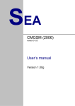
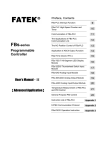
4.1 Front Panel
FBs-CML User’s Manual
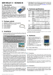
1. Introduction
Name
POW
LED red
Lights when CML is powered
RUN
LED green
CML operational mode:
Fast blink
Blink-Pause
Blink-Blink-Pause
1. PLC detection (after init)
2. Connection to SLAVE PLC
3. Connection to MASTER PLC
(PLC with FUN151 CLINK)
ERR
LED red
Error indication
Tx
LED red
Serial Communication to PLC
Rx
LED green
Serial
PLC
1.
2.
3.
4.
5.
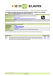
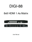
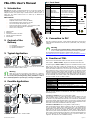
Point to point wireless connection of PLC’s
Multipoint wireless network of PLC’s (like RS485)
More independent wireless network’s in one place
Can be used directly with FBs-xxMC (Port 3)
No PLC program support is necessary – just use FUN151 (CLINK)
LEDs for device status and data flow signalization
Works in free 2.4 GHz band
2
3
2. Content of the
Delivery
4
5
FBs-CML
LED yellow
BTN
Communication
from
FBs-CML
RADIO MODULE
RF activity (Blinks whenever
any packet is sent)
BTN
Button
For future use
ANT
Antenna
Antenna connector
VF
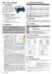
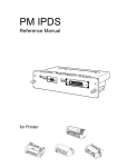
5. Connection to PLC
CML unit is connected to PLC FBs-… family using flat cable which is used for power
supply and data communication with PLC via Port 3 (9600 Baud, 7 bits, Even parity,
1 Stop bit).
1 pc of FBs-CML
1 pc of multidirectional antenna
1 pc printed documentation
Warning
Turn off all power (including battery) during installation of CML
to PLC or related equipments to prevent injury or damage to equipment!
For communication between PLC FUN151: CLINK in master PLC is used.
(See FATEK FBs-series User’s Manual–II; Chapter 12,13:Communication of FBs-PLC)
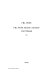
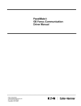
3. Typical Application
PLC FATEK
Tx
Rx
VF
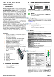
1
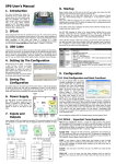
Indication LEDs
BTN button
Connection flat cable to PLC Fatek
Antenna connector RP SMA male
DIN rail holder
POW
ERR
Main features
Description
RUN
FBs-CML (CML for short) is wireless link between two or more PLC’s FATEK. It is
replacement for RS485 link between PLC’s. You can create two point link or
multipoint network. CML expects usage of function FUN151: CLINK in mode 0 on
master PLC. The wireless network works in a similar way as RS485 and is
transparent for PLC.
Element
FBs-CML
PLC FATEK
6. Function of CML
CML acts as PLC unit with station number 254. CML uses two sets of registers:
State registers: R2800 to R2809 – Registers are transmitted from CML to PLC
Command registers: R2810 to R2019 – Registers are transmitted from PLC to CML
In typical application CML connects two main PLC units. One of the PLC called
MASTER uses function FUN151: CLINK in mode 0.
Warning
FATEK PLC is not part of the delivery of this product. It is needed to
order independently. Any Fatek FBs-xxMC PLC can be used along with
CML. Turn off all power (including battery) during installation of CML to
PLC or related equipments to prevent injury or damage to equipment!
After power up CML starts to detect the connected PLC unit. It expects factory
default setting of PLC serial Port3 (9600 baud, 7 bits, Even parity, 1 stop bit). CML
tries all PLC station numbers from 1 to 253 one by one and waits for an answer
from connected PLC unit. In case there comes no answer, CML lights the red LED
ERR and then tests all station numbers again and again. In case an answer comes,
it means for CML that the connected PLC is SLAVE type (without CLINK function). In
case the connected PLC sends valid data to CML (station number 254) CML expects
the PLC is MASTER (uses FUN151: CLINK). CML operational mode is indicated by
the green LED RUN. See the next table for details:
LED RUN
4. Possible Application
PLC FATEK
Blink-Blink-Pause
Blink-Pause
CML is connected to SLAVE PLC (without FUN151: CLINK)
Permanently light
Reserved for future use
Fast blink 1:1
Fast blink 1:1
+ LED ERR
FBs-CML
Description
CML is not supplied
Detection of connected PLC in progress
No PLC detected
E.g. Wrong setting of Port3 on PLC
CML is connected to MASTER PLC (with FUN151: CLINK)
Dark
After the successful detection of connected PLC, CML starts to operate in one of
the following modes:
PLC FATEK
FBs-CML
PLC FATEK
FBs-CML
FBs-CML
Multipoint wireless network of PLC’s – similar to RS485
FBs-CML - V1.09-EN / 2013-03-19
PLC FATEK
Connection to SLAVE PLC (PLC is not using FUN151: CLINK)
CML periodically (1 per 15 sec) writes State registers (R2800 to R2809) to PLC and
reads Command registers (R2810 to R2819) from PLC. CML listens on preset
RF channel for any valid data packet and sends it to connected PLC (independently
on the station number inside the data packet). In case the PLC recognizes the data
packet has the same station number as PLC, it sends an answer data packet to CML
which sends it via RF back to MASTER PLC without any change.
Connection to MASTER PLC (PLC is using FUN151: CLINK in mode 0)
State and Command registers (R2800 to R2819) for CML are sent by MASTER PLC
as a part of FUN151: CLINK, (Port3, station number 254). The wireless RF data
communication is practically the same as in RS485 protocol. CML analyses the data
packet from PLC and in case the packet has another station number than CML
(other then 254) CML sends this data packet to RF on a preset RF channel and then
start to listen on preset RF channel for and answer. CML sends all data packets from
RF to connected PLC. All RF communication is done on preset RF channel (see
“Appendix – RF Channels” for list of available channels).
Page #1 of 3
CML State Registers Description (output registers from CML):
Register
Name
R2800
DI_STAMP 'CL'
R2801
DI_CHANNEL
R2802
DI_ALIVE
R2803
DI_VERSION
R2804
DI_RSSI
R2805
R2806
DI_STATUS
R2807
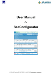
Example of usage function FUN151: CLINK
Pt: 3; PLC port 3 is used for communication with CML
Md: 0; FUN151: CLINK uses “mode 0”
SR: D1000; Link table for FUN151: CLINK
WR: R2000; Working registers for FUN151: CLINK
R2808(Lo)
R2809(Hi)
DI_TIME_UP
Description
0x434C ('CL') Sign of CML
Actual RF Channel number
See Appendix of this document
CML writes value 0x0001 whenever diagnostic
record is refreshed (cca 6 seconds). This is
intended for PLC program to check if CML is alive.
In this case PLC program will write a 0x0000 into
this register and wait for 0x0001 here.
Firmware version of CML:
In high byte is high version number
Inn low byte is low byte is low version number
RSSI value of the last received data packet
recalculated into dBm
Reserved
Reserved
x0H=Detection of PLC in progress
x1H=Connection to SLAVE PLC detected
x2H=Connection to MASTER PLC detected
1xH=Communication with PLC OK
32 bit counter which is incremented every second.
The counter is cleared after restart of CML. The
counter value indicates in a certain way how long
the CML is running without restart (so called
Uptime).
CML Command Registers Description (input registers for CML):
Register
Name
R2810
CF_STAMP ‘CL’
R2811
CF_CHANNEL
R2812
CF
_BANDWIDTH
R2813
Description
0x434C ('CL') CML Sign. Must be set to 'CL'.
Otherwise CML does not accept any command
(RF Channel set, Bandwidth set, Reset) from PLC!
RF Channel No. setting
See Appendix – RF Channels
RF Band Width setting
(Reserved for future usage)
Reserved
R2816
Reserved
If PLC writes value 0xF3A5 to this register the
CML will make reset of itself.
Reserved
R2817
Reserved
R2818
Reserved
R2819
Reserved
R2814
CF_RESET
R2815
7. Technical specification
7.1 General
Parameter
Link table setup for FUN151: CLINK
Width
Height
Depth (without
antenna)
Dimensions
Fixing
Power
Backup power
Temperature
Operating
Storage
Operational
Humidity
RF power
RF sensitivity
Automatic Frequency
Compensation (AFC)
RF frequency
RF freq. drift
Range
Range
Antenna
Connector
Inside building
Outdoor
Communication interface
Link table setup for FUN151: CLINK
Seq. 0: Command registers R2800 to R2809 for CML (station number 254)
Seq. 1: Status registers R2810 to R2819 from CML (station number 254)
Seq. 2: Reading of M0 state from remote PLC (station number 1) to MASTER PLC
FBs-CML - V1.09-EN / 2013-03-19
Symbol Conditions MIN.
w
h
d
TYP.
25
95
80
MAX.
DIN rail or flat panel screw fixing
5V / 40mA from power supply of PLC main unit
no
tA
-20
+60
-25
+70
hA
90
20
-100 dBm at 9.6 kbps and 1% packet error rate
up to +/- 400
Unit
mm
mm
mm
°C
°C
%
dBm
dBm
kHz
Free 2.4GHz band *) 2400 to 2483 MHz
Factory setting:
RF Channel 24, Band Width 81 kHz
+/- 50kHz in the range of operating temperatures kHz
Up to 20 m
m
Up to 200 m
m
RP SMA male (Device)
RP SMA female (Antenna)
Flat cable connected directly
into Fatek PLC
Warning
*) SRD Regulations (Short Range Device): International regulations
and national laws regulate the use of radio receivers and transmitters.
The most important regulations for the 2.4 GHz band are EN 300 440 and EN 300
328 (Europe), FCC CFR47 part 15.247 and 15.249 (USA), and ARIB STD-T66
(Japan). Please note that compliance with regulations is dependent on complete
system performance. It is the customer’s responsibility to ensure that the system
complies with regulations.
Page #2 of 3
8. FAQ
CML does not communicate with connected PLC. A) Please, check
setup of serial Port 3 in PLC (9600 Baud, 7 bits, even parity, 1 Stop bit).
If the problem persists try to initialize the PLC into factory default. (In
program WinProladder[Menu] -> PLC -> Clear PLC). B) Please, check
SLAVE PLC address setting (WinProladder[Menu] -> PLC -> Setting ->
Station Number). C) Check CML LED diodes (especially Rx and Tx).
How to reach the highest reliability of CML wireless
communication when transmitting data packets? CML uses free
2.4 GHz band. It means that not every data packet can be successfully
transmitted to remote CML due to jamming. Each packet is secured by
several levels of check sums. It’s recommended to send max. 50 bytes of
user data in each data packet. (50 bytes can transmitted by CML trough
RF in one data packet without necessity to divide them it into sub
packets. 50 bytes means transmission of eight 16bites registers e.g.
R1000 to R1007. For larger data packets the probability of successful
data transmission is lower.
Is it possible to connect two PLCs on longer distances outside
building? Use YAGI antenna or sector antenna.
After change of station number of SLAVE PLC, CML ceased to
communicate with PLC. After change of station number of PLC it’s
necessary to switch off and on the power supply of PLC.
Note: CML does not recognize serial parity on Port3 of PLC
Manufacturer: SEA, www.seapraha.cz
FATEK Manufacturer: FATEK Corporation, www.fatek.com
9. Warranty
General warranty period is 12 months after purchase, when eventual malfunction
device will be repaired free of charge in SEA company while shipping to SEA is paid
by customer and SEA pays for shipping back to customer. For SW there is 24
months warranty under following conditions:
Both CPU and PC software is sold “as is”. The software was created by the best
software engineers in SEA and was carefully tested both in SEA and also by SEA
customers using GSM applications products made in SEA. In spite of making all
possible to get error free software it can happen, that the software in CPU or PC
programming SW or their mutual interaction has some error under some specific
conditions. If such error is found and the description of the problem including
configuration file is sent by E-mail to SEA ltd., the error is removed free of charge
and SEA will send new SW by E-mail to customer.
SEA ltd. has NO RESPONSIBILITY for any
damage, lost, costs and any other problems direct or
inducted, caused by such SW error, by eventual device
malfunction from any reason or by undelivered SMS from the
device.
FBs-CML - V1.09-EN / 2013-03-19
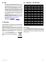
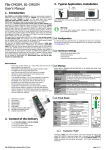
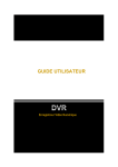
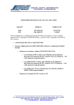
10. Appendix – RF Channels
Channel
No.
Frequency
[MHz]
Channel
No.
Frequency
[MHz]
Channel
No.
Frequency
[MHz]
0
1
2
3
4
5
6
7
8
9
10
11
12
13
14
15
16
17
18
19
20
21
22
23
24
25
26
27
28
29
2400,5
2401,5
2402,5
2403,5
2404,5
2405,5
2406,5
2407,5
2408,5
2409,5
2410,5
2411,5
2412,5
2413,5
2414,5
2415,5
2416,5
2417,5
2418,5
2419,5
2420,5
2421,5
2422,5
2423,5
2424,5
2425,5
2426,5
2427,5
2428,5
2429,5
30
31
32
33
34
35
36
37
38
39
40
41
42
43
44
45
46
47
48
49
50
51
52
53
54
55
56
57
58
59
2430,5
2431,5
2432,5
2433,5
2434,5
2435,5
2436,5
2437,5
2438,5
2439,5
2440,5
2441,5
2442,5
2443,5
2444,5
2445,5
2446,5
2447,5
2448,5
2449,5
2450,5
2451,5
2452,5
2453,5
2454,5
2455,5
2456,5
2457,5
2458,5
2459,5
60
61
62
63
64
65
66
67
68
69
70
71
72
73
74
75
76
77
78
79
80
81
82
83
2460,5
2461,5
2462,5
2463,5
2464,5
2465,5
2466,5
2467,5
2468,5
2469,5
2470,5
2471,5
2472,5
2473,5
2474,5
2475,5
2476,5
2477,5
2478,5
2479,5
2480,5
2481,5
2482,5
2483,5
Warning
SRD Regulations (Short Range Device): International regulations
and national laws regulate the use of radio receivers and transmitters.
The most important regulations for the 2.4 GHz band are EN 300 440 and EN 300
328 (Europe), FCC CFR47 part 15.247 and 15.249 (USA), and ARIB STD-T66
(Japan). Please note that compliance with regulations is dependent on complete
system performance. It is the customer’s responsibility to ensure that the system
complies with regulations.
Page #3 of 3