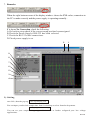
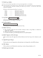
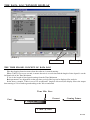
1
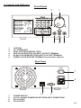
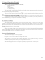
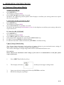
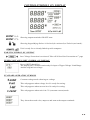
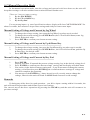
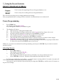
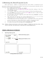
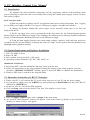
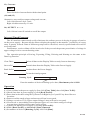
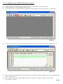
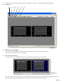
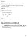
LABORATORY GRADE
SWITCHING MODE
PROGRAMMABLE POWER SUPPLY
with PC INTERFACE
7673-2405-0005
REV.1.7 - 06/2003
CONTENTS
1.
IMPORTANT SAFETY INSTRUCTIONS & PRECAUTIONS FOR USE
P.1
2.
SPECIFICATIONS
P.2
3.
INTRODUCTION
P.2
4.
CONTROLS & INDICATORS
P.3
5.
GENERAL OPERATING PRINCIPLE
P.4
6.
OPERATING INSTRUCTIONS
6.1. SETTING OF OPERATION MODE
6.2. MANUAL OPERATION MODE
P.5-6
P.7
7.
USING THE PRESET FEATURE
7.1. OPERATING THE TIMED PROGRAM
7.2. RUNNING THE TIMED PROGRAM
P.8
P.9
P.10-11
8.
MAINTENANCE
8.1. RECALIBRATION
8.2. TROUBLE SHOOTING
P.12
P.12
PC INTERFACE CONTROL USER MANUAL
9.1. INTRODUCTION
9.2. SYSTEM REQUIREMENT AND INSTALLATION
9.3. RS-232 INTERFACE OPERATION
9.4. RS-485 INTERFACE OPERATION
P.13
P.13
P.13-19
P.19-22
9.
1. IMPORTANT SAFETY INSTRUCTIONS
1.
2.
3.
4.
5.
6.
Do not use this apparatus near water.
Clean only with dry cloth.
Do not block any ventilation openings.
Do not install unit near any heat source or heating emitting devices.
Prevent the power cord from being walked on or pinched.
Unplug this unit during lighting storms or when unused for long periods of time.
PRECAUTIONS
1.
The unit must be used within its specified range.
The rated input voltages can be found on the rating label at the back the unit.
Before plugging into the AC supply, check with the rating label.
2.
This unit has a built-in Tracking O.V.P.(Over Voltage Protection) feature. In the event of
the output voltage becoming 10% greater than the set value, the O.V.P.
will be triggered and the output power will be cut off and > FAULT< warning appears.
When you get this warning, switch off the unit and remove all loading.
If you switch the unit back on again it should resume normal operation.
In the event this problem persists , the unit must be investigated by your agent.
3.
Only use the supplied software and optional accessories with this unit.
4.
Refer all servicing to qualified service personnel.
Warning !
Model SDP-2603, the maximum output voltage is up to 60Vdc.
It may be hazardous to touch metal part of the output terminals.
User must avoid touch live metal part of the output terminals.
P.1
2. Technical Specifications of SDP series Power Supplies
Specifications
SDP-2210
SDP-2405
SDP-2603
Output Voltage:
1-20VDC
1-40VDC
1-60VDC
Output Current:
0-10A
0-5A
0-3.3A
Ripple & Noise (P-P):
25mV
Load Regulation:
0.5% + 200mV
0.5%+100mV
0.5% +100mV
Line Regulation:
50mV
Input Voltage :
100 - 240 VAC, 50Hz / 60Hz
Display Meter:
4 digit - display LCD ammeter, voltmeter and power meter
Meter's Accuracy:
1.5% + 2 counts
LCD Module Back light : dim 48 x 6mm
Cooling System:
thermostatic control fan
Protection Devices:
Over Temperature, Tracking OVP
Approvals:
CE
Dimension (WxHxD):
193 x 98 x 215 (mm)
Weight:
3 KG
Accessory:
PC WindowsTM software, RS-232 cable and user's manual
Remarks:
Remote PC preset, activate and data logging
Optional RS-485 Adapter available
Adjustable upper voltage limit.
Power factor correction
3. INTRODUCTION
This series of laboratory grade, switching mode, programmable power supplies are ideal for
repetitive test routines in R&D, Production, Product Evaluation and various applications.
Information appearing on the large back-lit LCD makes the panel controls so simple and easy to
use in spite of its sophisticated features.
Because of the MCU, (Micro-Controller Unit ) and the related software,user re-calibration without
opening the casing is another added bonus.
When used with a standard PC, the supplied user friendly software and the built in RS-232 &
RS-485 interface provide 2 way communication thus would really enhance the unit's functionality.
Data logging with color graphic display in adjusting range voltage, current, watt, and time
periods are valuable tools in data analysis.
With RS-485 and the optional interface cable adapter, one PC can do remote control and data
logging as many as 31 power supplies.
More powerful software will be developed to meet the ever-changing demands in applications.
This series of power supplies have obtained the stringent safety approval EN-61010 for scientific
& laboratory equipment and the EMC 55011 for scientific, industrial and medical radio-frequency
equipment of the European EMC directive.
Please keep this manual in a safe place and contact your dealer for any special requirement in
application software or other feature.
P.2
4. Controls and Indicators
Front Panel
2
8888
... V
8888
... A
... W
8888
Timer 88 :88
m
V-const
V-set
I-const
I-set
Program
Recall
. . V
888
. . A
888
8
FAULT
OUTPUT
s
REMOTE
3
1.
2.
3.
4.
5.
6.
1
6
5
4
JOG DIAL
UP & DOWN KEY
DUAL FUCTION CONTROL KEYS
RED COLOR POSITIVE POLARITY OUTPUT TERMINAL
BLACK COLOR NEGATIVE POLARITY OUTPUT TERMINAL
GREEN COLOR GROUND TERMINAL (connected to chassis)
Back Panel
POWER
O
I
7
8
10
7.
8.
9.
10.
9
POWER SWITCH
AC 100 - 240VAC POWER SOCKET WITH INPUT POWER FUSE
RS-232 PORT
RS-485 PORT
P.3
5. General Operation Principle
There are four operation methods for this unit;
Manual Operation,
Presets,
Timed Program
PC Interface mode.
The large Liquid Crystal Display will guide you through various operations/procedures interactively
once you understand the operation principle.
There are 4 Dual Function Control Keys
for various operation modes and input states of the
unit.
To change/set operation mode (output on /off, key lock & etc.), in most cases, you need to use two
Dual Function keys to complete the operation.
To change input values of various settings ( voltage, current, preset number, cycles, time period & etc.),
use the ENTER key to get ready and to confirm the new settings.
The Liquid Crystal Display
The backlit display shows both the preset and actual output voltage , current levels at the output
terminals ; and status of constant current (CC) or constant voltage (CV) mode. Look out for new symbols
appearing on the display while doing inputting. They will guide you and remind you of the correct procedure.
Example: Inputting values of various settings
When a new setting (voltage, current, time periods & etc.) is ready for inputting, the hinting appearing
symbol of the related setting will be appearing on the display. After key in the required value, always follow
by pressing ENTER to confirm or to complete the operation.
Presets and Timed Subprograms
This unit has the capacity to store 10 programs.
Program 1 to 9 is for 9 sets of Presets of voltage and current.
The program 0 is reserved for the 20 timed subprograms, each is capable of storing 1 second to
99minutes operation period with its preset voltage and current levels.
The timed subprograms can be set to operate repeatedly in sequence from 1 to 9999 cycles.
P.4
6. OPERATING INSTRUCTIONS
6.1 Setting of Operation Modes
Output On/Off Mode
1.
2.
Press SHIFT key.
The display will show Sh:Ft.
Press (O/P On/Off) key within 3 seconds.
Watch for the appearing on/off symbol in the display to confirm your setting, otherwise repeat
the above procedure.
Lock/Unlock the Keypad and Jog Dial
1.
2.
Press SHIFT key.
The display will show Sh:Ft.
Press (Lock/Unlock) key within 3 seconds.
Watch for the appearing Lock/Unlock symbol in the display to confirm your setting, otherwise
repeat the above.
PC Interface RS-232/RS485
1.
2.
3.
4.
5.
Press SHIFT key.
The display will show Sh:Ft.
Press (RS232/485) key within 3 seconds.
Select desired PC Interface by pressing the (RS232/485) key.
For RS 232 press ENTER to confirm setting.
For RS 485 enter 485 address followed by ENTER to confirm setting.
Upper Voltage Limit Setting
This feature limits the upper level setting of output voltage to prevent inadvertent setting of
high output voltage which may damage your application.
The value of this upper voltage range limit will be retained until further reset.
Precaution:
Reset back to the maximum rated voltage of the unit is recommended to avoid false fault
report of the unit.
1.
Press SHIFT and follow by 0 key.
2.
The display will show
3.
4.
Input your desired voltage and follow by ENTER to confirm.
Recheck setting by repeating 1.
and the present upper voltage limit.
P.5
CONTROL SYMBOLS ON DISPLAY
Showing output terminals ON/OFF state.
Showing keypad &jog dial are in Locked (de-activated) or Unlock (activated) .
Unit is ready for or already linked up with computer.
WARNING SYMBOL ON DISPLAY
st
Over Voltage Protection is activated. Take off all load. See Precaution at 1 page
UPPER VOLTAGE LIMIT SYMBOL ON DISPLAY
Press SHIFT then 0 Key .
The display on LCD shows unit ready for input of Upper Voltage Limit Range
And the original set voltage.
STANDARD OPERATION SYMBOLS
Constant voltage mode showing set voltage
This only appears when voltage level is ready for setting.
This only appears when current level is ready for setting.
This only appears when unit is in CC (constant current) mode.
They show the actual volts, amperes and watt at the output terminals.
P.6
6.2 Manual Operation Mode
In the manual operation mode, once the voltage and current levels have been set, the unit will
keep these settings even after unit has been switched off until further reset.
There are 3 ways to input a setting;
1.
By the JOG WHEEL.
2.
By the UP or DOWN key.
3.
By the Key Pad.
For any wrong input, e.g. out of specification values, display will show " OUT OF RANGE " for
about 3 seconds , then returns to its previous settings and ready for correct new input.
Manual Setting of Voltage and Current by Jog Wheel
1.
2.
3.
To change the voltage setting, just rotate the Jog Wheel, no other step is needed.
To change the current setting, press ENTER twice ,the LCD will show I-set ,rotate Jog
Wheel for desired value.
Press ENTER to confirm your chosen current setting.
Manual Setting of Voltage and Current by Up & Down Key
1.
2.
3.
To change the voltage setting, just press the Up &Down Key, no other step is needed.
To change the current setting, press ENTER twice , the LCD will show I-set ,push the Up
& Down key for desired value.
Press ENTER to confirm your chosen current setting.
Manual Setting of Voltage and Current by Key Pad
1.
2.
3.
4.
Press ENTER.
Display will show V-set and the present voltage setting, key in the desired voltage level.
Press ENTER to confirm your chosen voltage setting, and the display will show I-set.
You can key in the desired current setting now , if you do not want to change the current
setting, you still need to press ENTER again to confirm the new settings of voltage and
current to complete the operation.
You must press the ENTER key 3 times in total even if you only want to change the
voltage, otherwise the unit will flash CANCELL and returns to its old settings
Remarks
If during any of the above key pad operation , you fail to input a setting within 10 seconds, the
unit will cancel the procedure and resume its previous settings.
You can exit any of the above operations by pressing the CLEAR key and the unit will resume to its
previous settings.
P.7
7. Using the Preset Features
PRESET PROGRAM SYMBOLS
Unit is ready for inputting of Preset Program Number (19).
Unit is ready for recalling a Preset Program Number.
The unit can store nine preset voltage and current settings.
Once programmed, these settings will be retained even when the unit is switched off.
Preset Programming
1.
Press PROG key
The display will show Program _
Key in Program Number (1-9) at the keypad
2.
The display will show :A)
The newly key in Program Number and
B)
The old settings of voltage and current with V-set ready for voltage to be reset.
C)
Set the required voltage level then press by ENTER to confirm.
D)
The display will show I-set ready for current level to be reset.
E)
Set required current level then press ENTER to confirm.
F)
The program will automatically advance to the next Preset (as shown in the display
Program_ section) ready for new setting of voltage and current.
G)
If you want to change the voltage and current setting of next Preset repeat procedure B to
E, otherwise just press ENTER to go to next Preset.
Whenever you want to terminate Preset Programming you can press CLEAR key to return to normal
operation mode.
Selecting Presets
1.
2.
3.
Press RECALL key
The display will show Recall__
Press the number key (1-9) .
The display will show the chosen Preset Number, its voltage and current level.
Press ENTER to activate .The unit will assume the chosen preset values.
If during any of the above procedures , you fail to input a setting within 10 seconds, the unit will
cancel the procedure and resume its previous settings.
You can exit any of the above operations by pressing the CLEAR key and the unit will resume to
its previous settings.
P.8
7.1 Operating the Timed Program
The unit can be programmed to operate up to 20 timed subprograms (1-19 STEP as shown in the
display). Each subprogram is capable of running a preset operation period of 1 second to 99 minutes &
99 seconds with its own preset voltage and current level.
The timed subprograms can be set to run in sequence repeatedly from 1 to 9999 cycles.
You can run the unit through the sequence of subprograms for the input cycles number unless
interrupted by pressing the CLEAR key.
Programming the Unit
1.
2.
3.
4.
5.
6.
7.
8.
9.
10.
Press PROG key
Press 0 KEY (to get to the Timed Program Mode)
and the display will show Program 0 StEP-.-.00
Input subprogram number 0 to 19 and press ENTER to confirm.
and the display will show StEP-.-.00 number and V-set ready for input.
Input voltage level followed by ENTER to confirm and display will show I-set.
Input current followed by ENTER to confirm.
The bottom left corner of the display will show Timer00m00and the appearing minute symbol m
Input minutes period(0-99) followed by ENTER to confirm.
The bottom left corner of the display will show Timer00m00s and the appearing second symbol s
Input seconds period (0-99) followed by ENTER to confirm.
The timed subprogram will automatically advance to next subprogram number ready for inputs
of new settings.
Repeat procedure 4 to 7.
A subprogram is confirmed to retain the new setting only when procedure 7 is completed .
You can input zero time period as a terminating subprogram.
Remarks:
A.)
B.)
Once the subprograms are filled, the unit will return to manual operation mode.
Any subprogram with zero time period will become the Terminating Subprogram.
For example if you set the subprogram7 with zero time period, all the subprograms after 7 (i.e.
8,9,10-------19) become non-existed.
And the timed program will only cycle from subprogram0 (STEP ) to subprogram 6.
You can use this feature to cut off the subprograms that are not required for the sequence.
C.)
A subprogram is confirmed to the new settings only when procedure 7 is done.
D.)
During any of the above procedures, if you fail to input a setting within 10 seconds, the unit will
exit from that procedure and return to manual operation mode.
E.)
For any wrong input, display will show OUT OF RANGE for about 3 seconds and then returns
to its previous procedure/settings ready for correct new input.
P.9
7.2 R u n n i n g t h e T i m e d P r o g r a m C y c l e s
Once the desired number of subprograms have been filled as explained in the
previous section, all the presets of voltage ,current levels and operation periods will be
retained until further programming.
1.
P r e s s R E C A L L f o l l o w e d b y t h e 0 K E Y.
The display will show STEP 00 and Recall 0 and the settings of the first
T i m e d Su b p r o g r a m .
2.
Use the UP^ or DN/ keys to check the settings of all the timed subprograms.
3.
Press ENTER and the display will show CYC-0000, the unit is ready for input
of repetitive operation cycles.
4.
Key in number of cycles required,1-9999 and followed by ENTER to start the
cycle operation.
5.
The unit will run through the Timed Subprogram 0 to 19 or 0 to any
subprogram prior to the subprogram with zero time period .
6.
The display will show the on-going cycle's count down time of the operation
period, actual and set voltage and current ,number of cycles executed.
7.
Yo u c a n a l s o s e e t h e p o w e r w a t t d i s p l a y i f y o u p r e s s E N T E R ,
8.
To return to the previous display press ENTER again
Note : Beware that the life span of the power supply is limited by the life of the relay
which is of 100 x 103 operation as stated by the relay manufacturer.
TIMED PROGRAM SYMBOLS
1.
Inputting Subprograms
StEP (timed subprogram)
Subprogram Number (0-19)
Setting minutes and seconds
P.10
2.
S y m b o l s i n R u n n i n g Ti m e d P r o g r a m C y c l e
U n i t r e a d y f o r r e c h e c k o f s e t t i n g o f a l l t h e t i m e d subprograms
Subprogram Number (0-19)
Unit ready for inputting number of cycles
Number of cycles executed
P.11
8. MAINTENANCE
8.1 RECALIBRATION
Introduction
This in-case recalibration is to reduce the difference between the Set values and the displayed
values on the LCD Display. You only use the recalibration when the difference is greater than 0.1V for
voltage or 0.01Afor current. The whole recalibration for voltages and current takes less than 15
minutes. It is performed by a proprietary software using regression algorithm.
The recalibration software is compatible to Window XP, Me, 2000, 98SE, 98.
Installation of the recalibration software
1. In the installation disk, run Setup.exe inside the folder of Re-calibration to install the
recalibration software.
2. Follow the instructions in the setup program.
3. Finally a SDP Recalibration icon is created in the Program Menu.
Operation Instruction
1. Ensure your PC is off, connect RS-232 to serial com. port of your PC and the power supply.
2. On Your Power Supply, press [SHIFT] key, then quickly press [RS232/485] key and select
RS-232 followed by [ENTER] key.
3. Switch on your PC and run the SDP recalibration software.
4. Follow the instructions shown in the software.
8.2 TROUBLE SHOOTING
1.Key pad and jog dial do not work
Check key lock symbol if in Lock state , unlock unit by SHIFT then LOCK/UNLOCK key,
otherwise switch off unit and switch on again to see if problem persists.
2.No output power
Check output on/off symbol on display. Press SHIFT then O/P ON/OFF
3.Cannot get high voltage setting within the rated maximum.
Check upper voltage limit setting by SHIFT then 0 Key.
Reset to rated max. voltage.
4.CANCELL symbol keeps appearing in all keying in operation.
Keying in time not fast enough as only 10 seconds are allowed for data inputting
And 3 seconds for operation mode setting.
5.OUT OF RANGE keeps appearing .
A. Check if setting is within the rated range.
B. If this occurs during voltage setting, see point 3.
P.12
9. PC Interface Control User Manual
9.1 Introduction
We integrate the micro-controller technology and our proprietary software with switching mode
power technology to make this unit a user friendly, time saving and reliable power supply. In fact it is more
than a power supply!
In PC interface mode:
1. With our proprietary software one PC can perform remote access/control and output data logg ing
for one SDP power supply with RS-232 or up to 31 SDP power supplies using RS-485 interface.
2. Outputs for dynamic loading like power surges can be recorded, stored (also as xls file) and
displayed in the PC.
3. The PC can input, store, retrieve and transfer all the data entries for the Timed Programs and the
Memory Presets to the SDP power supply. Thus eliminates the tedious process of keying in data for different
groups of Timed Programs and Memory Presets to the SDP power supply.
4. Using the data logging function, the actual output voltages, amperes, watts and time period are
recorded in the PC for later analysis. Adjusting the scales of voltage, current, power and time parameters can
Highlight further graphical analysis.
9.2 System Requirement and Software Installation
1.
2.
3.
4.
CPU 450 MHz or above
Ram 128 MB
Min. monitor screen area 800 x 600 pixels.
Operating systems WindowÒ Xp, Me, 2000, 98SE, 98.
Installation of Software
1. Run Setup.EXE with the installation disk that comes with the unit.
2. Follow the instructions in the setup program. During the running of the setup program, you may
encounter 'VERSION CONFLICT' remarks, ignore it and click 'YES' to complete the installation.
3. Finally a SDP icon is created in the Program Menu.
9.3 Operation Instruction for RS-232 Interface
1. Ensure your PC is off ,connect RS-232 to the serial com port of your PC and the power supply.
2. On your power supply, press the [SHIFT] key, then quickly press [RS232/485] key and select RS-232
followed by [ENTER] key.
3. Switch on your PC and run the SDP program.
4. Click on Setup, and select the disired Com. Port. The default is set at Com 1.
5. Click on Supply Connect, then click on Single in the drop menu.
6. An "Internal Timed Program" window will appear. Click on the Data Log header on top left and a
Window as shown in Fig 1 will appear.
P.13
7. Remarks:
When the right bottom corner of the display window shows the UVL value, connection to
the PC is made correctly and the power supply is operating normally .
If it shows No Connection, check the following:
A.Go back to setup check if the correct comp port has been assigned.
B.Check the Power Supply if RS-232 has been selected
C.Check the RS-232 cable connections.
D.Check power supply is on.
2
1
9
8
7
6
5
3
4
(FIG. 1)
1). Setting
one click , then the pop-up
Data log Sampling Time
You can input your desired sample time from 1 second up or select from the drop menu.
Voltage Upper Limit Setting
You can set your output voltage upper limit value to further safeguard your low voltage
applications.
P.14
2). Data Log window
A). You can use the Data Log window to view present output data or stored data .
B). All the parameters at the bottom of the window display can be changed by direct entry from the PC
(with decimal point) and then confirm by the Enter key of the PC , or select the values from
respective drop menu.
Parameters at the bottom of the Data Log window:
V Min.
V Max.
C Min.
C Max.
W Min.
W Max.
3). Log Name
-------------------------------------------
Minimum voltage level.
Maximum voltage level.
Minimum current level.
Maximum current level.
Minimum power level in watt.
Maximum power level in watt.
Untitle
Click cursor on "Untitle", type in a name for your log.
Note how the ###(5) icon changes to solid color
4). Log Description
You can type in your detail description of your log.
5). ##### Save Log
a) This function (and the icon) becomes effective when a Log Name is entered to
replace the "Untitle".
b) Click on it will save the current data onto the PC.
c) To retrieve the data , go to the drop menu at (3) Log Description.
6). ##### Export to a file of xls type
Click on this icon will export the collected data (in the Save Log) in xls format to your
PC.
7). Open file log of xls type
Click on this icon will import the collected data in xls format file to the SDP software.
8). XXX Delete
Click on this icon will delete the current log or retrieved log on display at (3).
9). Print Log in xls format.
P.15
THE DATA LOG WINDOW DISPLAY
( FIG. 2 )
Time Minimum
Time Length
THE TIME FRAME CONCEPT OF DATA LOG
The data logging function starts when the software is started running.
When T Min is set to zero second, it means the unit is on real time and the length of time lapsed is on the
left hand side of the Time Minimum.
T Len is the length of time lapsed starting from the Time Minimum.
Both parameters are adjustable so that any time period of the log can be displayed for analysis.
In the above example, T Min is set to 320 second and T length to 60 second, the display shows the output
data starting at 320 seconds ago and ending at the 380 second mark
Time Min. Zero
Present
Past
Coming Future
T length 60S
T Min. @ 320S
P.16
General Operation
Please refer to (Fig. 3) for the following description.
10
11
12
13
14
15
16
( FIG. 3 )
10). Power Supply Description:
manson sdp serial no S2405000
You may click on and assign an identification for your power supply in use.
Actually this feature is mainly for multiple power supplies application with RS-485.
11). Address :
00
This function is for multiple power supplies application.
Each power supply has a unique address.
Ignore this function when using RS-232.
12). Voltage:
##.# V
Enter the desired output voltage with decimal point.
P.17
13). Current:
#.## A
Enter the desired current limit with decimal point.
(14) and (15)
Alternative way to adjust output voltage and current ;
Left click increases by 0.1 unit
Right click decreases by 0.1 unit.
16). OUTPUT o------o
Left click on icon will switch on or off the output.
Internal Timed Program
The PC interface remote mode really eliminates the tedious process in keying in groups of entries
on the power supply . Because all the data are displayed together in the monitor , possibility of wrong
entry is greatly reduced. Data of different groups can be classified, stored ,exported and retrieved for
use at any time.
Furthermore, retrieved data will be in red color if they exceed the present preset limits of voltage in
upper voltage level or current limiting value.
The operation principle of Saving, Exporting, Filing, Deleting and Printing are the same as the
Data Log function.
Clear Table
Delete all data on the Display Table to ready for new data entry.
Save to PS
Transfer data from the Display Table to the Power Supply.
Read fro PS
Get data from the Power Supply.
Run
To run the timed program.
Running Cycle
9999
Enter the number of desired running cycles here, Maximum cycles is 9999.
Operation
1.) Clear old data in the power supply by first click [Clear Table] then click [Save To PS].
2.) Check if no data in power supply by click [Read Fro PS].
3.) Enter data in the table using the Up Down Left Right keys of your PC key board for new
locations.
4.) Data exceed the rated voltage and current will not be accepted.
5.) Voltage exceed set UVL (Upper output Voltage Limit) will not be accepted.
6.) If retrieved or entered data exceed present Upper or Lower limit setting of voltage
/current/time, the data will becomes red in colour.
7.) Transfer set data to power supply by clicking [Save to PS].
8.) Click [Read Fro PS] to initiate the [Run] command.
9.) Set number of desired [Running Cycle] and Click [Run].
P.18
Internal Preset Memory
The operation principle is the same as Internal Timed Program.
To activate the selected preset click on the box of the [Select] column then click Run.
If retrieved or entered data exceed present Upper or Lower limit setting of voltage /current/time,
the data will becomes red in colour.
9.4 Operation Instruction for RS-485 Interface
This interface operation is provided for remote access/control up to 31 SDP Power Supplies.
The setup procedures are as below:
9.4.1 Configuration of each power supply
1. Ensure your PC is off, Use RS-485 Plug to connect the Power Supplies to each other.
2. Make sure the PC are interconnected, use RS-485 to RS-232 converter to connect one of the power
supplies and the serial com port of your PC(Fig.4).
RS-485 to RS-232
Converter
RS-485
( FIG. 4 )
3. On your power supplies, press [SHIFT] key, then quickly press [RS-232/485] key and select
RS-485.
4. A 3-digit number will appear. This number is the address assigned to the power supply and will be
used in the software. 5.Using the Key Pad to key in the address to assign for each power supply. The
range is 001 ~ 031 and each of the power supplies requires an unique address.
6. Switch on your PC and run the SDP program.
7. Click on Setup, and select the desired Com. Port. The default is set at Com 1.
8. In the tool bar, Click on Supply Connect, then click on Single in the drop menu.
9. An Internal Timed Program window will appear.
10. By choosing the address in the Address field (Fig.5) you can input the desired settings for each
power supply as given in Section 9.3 on page 12.
( FIG. 5 )
P.19
9.4.2 Configuration of Multi Windows Analysis
1. In the tool bar, Click on Supply Connect, then click on Multi in the drop menu.
2. A Multi Windows window(Fig.6) will appear.
3. Click on the icon (circled as below), a Multi Power Supply Connect Setup(Fig.7) will appear.
( FIG. 6 )
4. Click on AutoScan Connect, the window will show the connected power supply indicted as "Y".
( FIG. 7 )
5. Click on the box along the Visible Column to set the desired power supply to be visible in Multiple
Data Log Window.
6. You can type in the description and location of your power supplies in the Location and
Description Column.
P.20
7. Click on Close icon(at right bottom of window) to return to Multiple Data Log Window.
8. Remarks:
3
4
2
5
1
6
( FIG. 8 )
1). Multi Alleyway Display
one click, it will display the Data log and output data of all the power supplies.
It will activate the icon (2), (3) and (4).
2). Show Digital and Log
one click, it will show both the data log of all the connected power supplies.
( FIG. 9 )
You can click on the data log to select the power supply, the data log will highlight in blue and the
address bar in the left bottom window will show the selected power supply.
P.21
3). Show Digital
one click, it will show the digital readings of all the connected power supplies.
4). Show Log
one click, it will show the data log of all the connected power supplies.
5). Single Alleyway Display
one click, it will only display the Data log of the selected the power supply(Fig. 10).
It will disable the icon (2), (3) and (4).
The parameters at the bottom are same as the Data Log Window in RS-232 Interface(Page 14).
The All SP Tick box --- Tick to apply the parameters to all Data Log Window in Multi Alleyway
Display.
6). Log Thumbnails Size Setup
one click, it let user to adjust the window size of the Data log Window in Multi Alleyway Display.
Use the sliders to adjust the height and width of the Data Log Windows.
Scale 4:3 tick box can enable 4:3 screen size for the Data Log Windows.
( FIG. 10 )
7
8
9
10
11
12
13
14
7) Save Log
a) Click on it and a save log window(Fig.13) will appear.
( FIG. 11 )
b)
c)
d)
e)
f)
Click on the box along the Save column to choose the desired power supplies' data log to save.
Type in the Table Name.
Click Save will save the current data onto the PC.
To retrieve data, go to the drop menu at Log (13).
To delete the log data, click on Delete Log icon (8).
P.22
8). Delete Log
It can delete the log data in the PC.
9). Export to a file log of xls type
Click on this icon will export the collected data (in Data Log) in xls format to your PC.
10).Open File Log of xls type
Click on this icon will import the collected data in xls fomat file to the SDP software.
11).Close File Log of xls type
Click on this icon will close the import xls format file.
12).Print Log
Print Log in xls format.
13).Log
Click on it to select the save log data.
14).Sample
Click on it to select the sampling time.
( FIG. 12 )
15
16
15).SetV
Click on it and type in to change the voltage setting of the selected power supply.
16).SetC
Click on it and type in to change the current setting of the selected power supply.
SAMPLING TIME & AVAILABLE LOG TIME RECORD
The available log time record for each log is 1800 x sampling time.
Hence a sampling time of 3 seconds will allow log time record of up to 1800x3 = 5400 seconds
a sampling time of 6 seconds will allow log time record of up to 1800x6 = 10800 seconds
When logging record is in excess of allowable log time record , the new log will
overwrite the first log record.
END