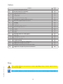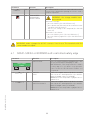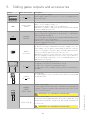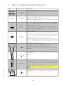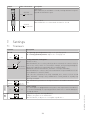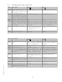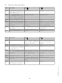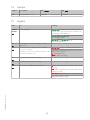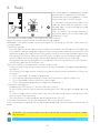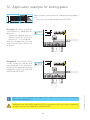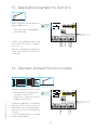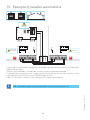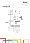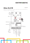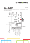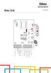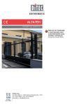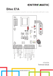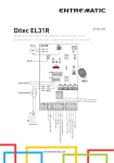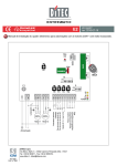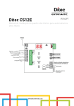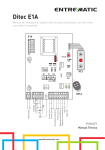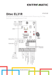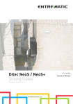
1
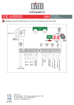
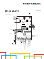
Ditec EL31R
IP1851EN
Installation Manual for control panel for 24V automations with
built-in radio.
Motor
EL31R
24V=
-M
+M
ENC
B
A
T
BATK3
A
N
T
JR1
IN
SA
11
POWER
12
B
ON
A
ON
SIG
AUX
COM
PRG
1 2 3 4 5 6 7 8
GOL4
1 2 3 4 5 6
Safety switch
VA
24V~ SAFETY
Transformer
VC
TC
R1
12 11 0
14 0
1 5 9 13 20
Step-by-step
Stop
Gate open indicator light
Partial opening
C NO
Flashing light
Limit switch
Limit switch
0 1 6 8 41
www.ditecentrematic.com
Safety test
Safety stop
Safety reopening
Power supply
Accessories output
F1
28
IP1851EN - 2015-11-24
Index
Subject
Page
1.
General safety precautions
30
2.
EC declaration of conformity
31
3.
Technical specifications
31
Applications
31
Commands
32
Self-controlled safety edge
33
5.
Sliding gates outputs and accessories
34
6.
Barriers outputs and accessories
35
7.
Settings
36
7.1
Trimmers
36
7.2
Sliding gates dip-switches
37
7.3
Barriers dip-switches
38
7.4
Jumper
39
7.5
Signals
39
8.
Radio
40
9.
Working modes for sliding gates
41
10.
Start-up
42
10.1
Sliding gates start-up
42
10.2
Barriers start-up
43
11.
Troubleshooting
44
12.
Application example for sliding gates
46
13.
Application example for barriers
47
14.
Example of operator present function mode
47
15.
Application example for parallel automations
48
3.1
4.
4.1
IP1851EN - 2015-11-24
Key
This symbol indicates instructions or notes regarding safety, to which special attention must be paid.
i
This symbol indicates useful information for the correct functioning of the product.
29
1. General safety precautions
Failure to observe the information in this manual may result
in minor personal injury or damage to equipment.
Save these instructions for future reference.
This installation manual is intended for qualified personnel only.
Installation, electrical connections and adjustments must be performed in accordance
with Good Working Methods and in compliance with the present standards.
Read the instructions carefully before installing the product.
Bad installation could be dangerous.
The packaging materials (plastic, polystyrene, etc.) should not be discarded in the environment or left within reach of children, as these are a potential source of danger.
Before installing the product, make sure it is in perfect condition.
Do not install the product in explosive areas and atmospheres: the presence of inflammable
gas or fumes represents a serious safety hazard.
The safety devices (photocells, safety edges, emergency stops, etc.) must be installed taking
into account: applicable laws and directives, Good Working Methods, installation premises,
system operating logic and the forces developed by the automation.
Before connecting the power supply, make sure the plate data correspond to that of the
mains power supply.
An omnipolar disconnection switch with minimum contact gaps of 3 mm must be included
in the mains supply.
Check that upstream of the electrical installation there is an adequate residual current circuit
breaker and a suitable overcurrent cutout.
When requested, connect the automation to an effective earthing system that complies with
current safety standards.
During installation, maintenance and repair operations, cut off the power supply before opening
the cover to access the electrical parts.
The electronic parts must be handled using earthed antistatic conductive arms.
The manufacturer of the motorisation declines all responsibility in the event of component
parts being fitted that are not compatible with the safe and correct operation.
Use original spare parts only for repairs or replacements of products.
Fix the control panel permanently. Pass the cables along the lower side of the container.
If they are accessible, block the cables with cable glands (not supplied). Keep the line and motor
conductors separated from the command conductors by at least 8mm in the terminal boards
connection points (e.g. using straps).
Connect together the protection conductors (yellow/green) of the line and the motors, using the
clamp supplied.
At the end of the installation, close the container.
30
IP1851EN - 2015-11-24
1.1 Installation precautions
2. EC Declaration of Conformity
The manufacturer Entrematic Group AB, with headquarters in Lodjursgatan 10, SE-261 44 Landskrona, Sweden,
declares that the EL31R type control panel complies with the conditions of the following EC
directives:
EMC Directive 2004/108/EC
Low Voltage Directive 2006/95/EC
R&TTE Directive 1999/5/EC
Landskrona, 29-01-2013
Marco Pietro Zini
(President & CEO)
3. Technical specifications
Storage module
3M1CR3
Power supply
230 V~ 50/60 Hz
ALTA5EH
CROSS5EH
CROSS5EH1
3M1CR5
3M1CR5C5
230 V~ 50/60 Hz
F1 fuse
F1,6A
F1,6A
Motor output
24 V
8A
24 V
9,5 A
24 V
14 A
Accessories
power supply
24 V
0,3 A
24 V
0,3 A
24 V
0,3 A
Temperature
min -20° C
max +55° C
min -20° C
max +55° C
min -20° C
max +55° C
min -20° C
max +55° C
Degree of
protection
IP24D
IP24D
IP24D
IP24D
Radio frequency
433,92 MHz
433,92 MHz
433,92 MHz
433,92 MHz
Stor able tr ansmitters
100
(200-BIXMR2)
100
(200-BIXMR2)
100
(200-BIXMR2)
100 (200-BIXMR2)
CROSS3E
i
ALTA7EH
CROSS7EH
CROSS7EH1
3M1CR7
3M1CR7C5
230 V~ 50/60 Hz
F2A
3M1QK
3M1QKC7
230 V~ 50/60 Hz
F1,6A
24 V
7A
24 V
0,3 A
N.B.: The given operating and performance features can only be guaranteed with the
use of DITEC Entrematic accessories and safety devices.
3.1 Applications
IP1851EN - 2015-11-24
QIK7EH
QIK7YEH
3M1QKC7
3M1CR5C5
3M1CR7C5
31
Command
1
5
N.O.
Function
Description
STEP-BY-STEP
WITH AUTOMATIC
CLOSING
With DIP1A=OFF and TC<MAX, closing of the contact
activates an opening or closing operation in the following
sequence: opening-stop-closing-opening.
N.B.: the stop is not permanent, but has the duration set
with the TC trimmer.
STEP-BY-STEP
WITHOUT AUTOMATIC
CLOSING
With DIP1A=OFF and TC=MAX, closing of the contact
activates an opening or closing operation in the following
sequence: opening-stop-closing-opening.
OPENING
WITH AUTOMATIC
CLOSING
With DIP1A=ON and TC<MAX, closing of the contact
activates an opening operation.
OPENING WITHOUT
AUTOMATIC
CLOSING
With DIP1A=ON and TC=MAX, closing of the contact
activates an opening operation.
N.B.: Once the automation stops, command 1-5 performs
the opposite operation to the one performed before the
stop.
6
N.O.
CLOSING
With DIP2B=OFF, closing of the contact activates a closing operation.
1
6
N.C.
OPENING
SAFETY CONTACT
With DIP2B=ON, opening of the safety contact stops and
prevents any movement.
1
8
N.C.
REVERSAL
SAFETY CONTACT
Opening the safety contact triggers a reversal of the
movement (reopening) during the closing operation.
1
9
N.C.
STOP
Opening the safety contact stops the current operation.
1
9
N.O.
OPERATOR PRESENT
CONTROL
Opening of contact 1-9 enables the operator present
function.
- opening with operator present 1-5 [with DIP1A=ON
and TC=MAX];
- closing with operator present 1-6 [with DIP2B=OFF].
N.B.: any safety devices, automatic closing and plug-in
cards in the AUX housing are disabled.
1
20
N.O.
PARTIAL
OPENING
With DIP3B=ON, closing of the contact activates a partial opening operation.
Once the automation stops, the partial opening control
performs the opposite operation to the one performed
before the stop.
AUTOMATIC
CLOSING
With DIP3B=OFF, permanent closing of the contact enables automatic closing.
QIK
CROSS
1
1
20
N.O.
AUTOMATIC
CLOSING
Permanent closing of the contact enables automatic
closing.
0
11
N.C.
CLOSING LIMIT
SWITCH
Opening of the contact stops the closing operation.
0
12
N.C.
OPENING LIMIT
SWITCH
Opening of the contact stops the opening operation.
SAFETY TEST
With DIP6A=ON, connecting terminal 41 enables a safety
edge test cycle before every operation. If the test fails the
SA LED flashes and the test is repeated.
41
32
IP1851EN - 2015-11-24
4. Commands
Command
PRG
Function
Description
N.C.
SAFETY SWITCH
The SAFETY SWITCH contact is connected to the release
system of the automation. Opening the release contact
stops the operation.
N.O.
TRANSMITTER
STORAGE AND
CANCELLATION
WARNING: the storage module must
be inserted.
Transmitter storage:
- press the PRG key (the SIG LED turns on),
- proceed with transmission from the transmitter to be
stored (the SIG LED flashes),
- wait 10 s for storage to be completed (the SIG LED
turns off).
Transmitter cancellation:
- press the PRG key for 3 s (the SIG LED flashes),
- press the PRG key again for 3 s (the SIG LED flashes
faster).
WARNING: make a jumper for all N.C. contacts if not in use. The terminals with the
same number are equal.
4.1 SOFA1-SOFA2 or GOPAVRS self-controlled safety edge
Command
Function
Description
SAFETY TEST
Place the SOFA1-SOFA2 or GOPAVRS device into
the special housing for AUX plug-in cards.
With DIP6A=ON, connecting terminal 41 enables
a safety edge test cycle before every operation.
If the test fails the SA LED flashes and the test
is repeated.
SOFA1-SOFA2
GOPAV
6
N.C.
SAFETY
STOP
Connect the output contact of the device to terminals 1-6 on the control panel (in series with the
photocell output contact, if installed).
WARNING: if not used, make a jumper for terminals 41-6.
1
8
N.C.
REVERSE
SAFETY CONTACT
Connect the output contact of the device to terminals 1-8 on the control panel (in series with the
photocell output contact, if installed).
WARNING: if not used, make a jumper for terminals 41-8.
IP1851EN - 2015-11-24
1
33
5. Sliding gates outputs and accessories
Output
Value - Accessories
- +
0 1
AUX
COM
BAT
24 V 0.3 A
Accessories power supply.
Power supply output for external accessories, including automation status lamps.
SOFA1-SOFA2
GOPAV
The control panel is fitted with a housing for a plug-in card, such as
radio receivers, magnetic loops, etc.
Operating of the plug-in card is selected by DIP1A.
WARNING: the plug-in cards must be inserted and removed with
the power supply disconnected.
STORAGE
MODULE
The storage module allows remote controls to be stored and the
type of control panel application to be defined (see TECHNICAL
SPECIFICATIONS on page 4).
If the control panel is replaced, the storage module being used can
be inserted in the new control panel.
WARNING: the storage module must be inserted and removed with
the power supply disconnected.
BATK3
2x12 V 2Ah
Barrier operation.
The batteries are kept charged when the power supply is on. If the
power supply is off, the panel is powered by the batteries until the
power is re-establish or until the battery voltage drops below the
safety threshold. The panel turns off in the last case.
WARNING: the batteries must always be connected to the control
panel for charging. Periodically check the efficiency of the batteries.
N.B.: the operating temperature of the rechargeable batteries is
approximately +5°C/+40°C.
1 5 9 13 20
24 V 3 W
14 0
LAMPH
24 V 25 W
C NO
Description
LUXK3E
LUXK7
230 V~ 60 W
Automation status light (proportional)
The light goes off when the automation is closed.
The light comes on when the automation is open.
The light flashes with a variable frequency while the automation is
operating.
Flashing light.
The flashing light activates simultaneously with the opening and
closing operation.
Internal courtesy light.
A courtesy light that turns on for 180 seconds with every opening (total
or partial), step-by-step and closing command can be connected in
series to the NO contact.
L N
230 V~ 400 W
External courtesy light.
An external courtesy light that turns on for 180 seconds with every
opening (total or partial), step-by-step and closing command can
be connected.
WARNING: use a double insulated cable
34
IP1851EN - 2015-11-24
WARNING: use a double insulated cable
6. Barrier outputs and accessories
Output
Value - Accessories
- +
0 1
24 V 0,3 A
AUX
COM
BAT
SOFA1-SOFA2
GOPAV
STORAGE
MODULE
The storage module allows remote controls to be stored and the
type of control panel application to be defined (see TECHNICAL
SPECIFICATIONS on page 4).
If the control panel is replaced, the storage module being used can
be inserted in the new control panel.
WARNING: the storage module must be inserted and removed with
the power supply disconnected.
BATK3
2x12 V 2Ah
Barrier operation.
The batteries are kept charged when the power supply is on. If the
power supply is off, the panel is powered by the batteries until the
power is re-establish or until the battery voltage drops below the
safety threshold. The panel turns off in the last case.
WARNING: the batteries must always be connected to the control
panel for charging. Periodically check the efficiency of the batteries.
N.B.: the operating temperature of the rechargeable batteries is
approximately +5°C/+40°C.
24 V 3 W
14 0
LAMPH
24 V 25 W
C NO
230 V~ 400 W
Automation status lamp (proportional)
The light goes off when the automation is closed.
The light comes on when the automation is open.
The light flashes with a variable frequency while the automation is
operating.
Flashing light.
WITH DIP5A=OFF it is activated during the opening and closing
operations.
External courtesy light.
With DIP5A=OFF, a courtesy light can be connected in series to the NO
contact, which activates for 180 s on each opening (total or partial),
step-by-step and closing command.
WARNING: use a double insulated cable
L N
IP1851EN - 2015-11-24
Accessories power supply.
Power supply output for external accessories, including automation status lamps.
The control panel is fitted with a housing for a plug-in card, such as
radio receivers, magnetic loops, etc.
Operating of the plug-in card is selected by DIP1A.
WARNING: the plug-in cards must be inserted and removed with
the power supply disconnected.
1 5 9 13 20
C NO
Description
14 0
LAMPH
24 V 25 W
Flashing light.
WITH DIP5A=ON it is activated during the opening and closing
operations.
35
Output
Value - Accessories
14 0
QIKLUX
24 V 300 mA max
14 0
QIKAFE
24 V 300 mA max
Description
Lighting kit.
With DIP5A=ON, on with barrier closed, flashing with barrier operating and off with barrier open.
Electric block.
With DIP5A=ON it is activated with the barrier closed.
7.Settings
7.1 Trimmers
Trimmer
Description
VA - VC
VA - Opening speed adjustment. Adjusts the opening speed.
VC - Closing speed adjustment. Adjusts the closing speed.
max
min
12
0
s
TC
MIN=0 s
MAX=disabled
TC
With DIP3B=OFF, permanent closing of contact 1-20 enables automatic closing.
MAX=120 s
R1
min
max
R1
min
max
Power setting.
The control panel is equipped with a safety device that stops motion if an obstacle
is encountered during the opening operation and reverses motion during the
closing operation.
Adjustment of power and stop distance.
It adjusts the power of the automation.
With DIP7B=OFF, it adjusts the closing bar stop distance.
36
IP1851EN - 2015-11-24
CROSS
MIN=0 s
QIK
Setting automatic closing time.
From 0 to 120 s.
With DIP3A=OFF, once a safety switch has been activated, the counter starts as
soon as the safety switch is released (for example, after passing through the
photocells), and lasts for a period of time set with TC (50%).
WARNING: with QIK automations, automatic closing is immediate.
With DIP3A=ON, the counter starts when automation is opened and lasts for the
entire duration set with TC (100%).
N.B.: after the activation of the stop command, once contact 1-9 has closed
again, automatic closing is only enabled after a total, partial or step-by-step
opening command.
IP1851EN - 2015-11-24
7.2 Sliding gates dip-switches
DIP A
Description
DIP1A
Command functions 1-5.
Step-by-step
N.B.: it also sets operating on
the AUX plug-in card.
Opening.
DIP2A
Selecting opening direction.
Opening to the right.
The opening direction is intended by viewing the automation
from the side being examined.
Opening to the left.
DIP3A
Automatic closing time restore
50%
100%
DIP4A
Automation status at power on.
Indicates how the control panel
considers automation when
powered up.
Open.
N.B.: with limit switches installed, we recommend setting
DIP4A=OFF.
Closed.
N.B.: if the automatic closing
function is not used, we recommend setting DIP4=ON.
DIP5A
Preflashing for 3 seconds.
Disabled during opening.
Enabled for both opening and
Enabled only with automatic closing.
closing with TC >3 s.
DIP6A
Safety test terminal 41.
Disabled.
Enabled.
DIP B
Description
OFF
ON
DIP1B
Reversal safety contact opera- With automation stopped and With automation stopped and
tion.
contact 1-8 open, opening op- 1-8 open, all operations are
erations are permitted.
disabled.
DIP2B
Command functions 1-6.
Closing.
Stop.
DIP3B
Command functions 1-20.
Automatic closing on.
Partial opening command.
DIP4B
Selection of maximum working Normal closing force and Reduced closing force and longforces limit and adjustment of reduced stop distance that er stop distance irrespective
stop distance.
changes according to speed.
of speed.
DIP5B
Encoder selection.
DIP6B
Current profile.
(Automations with
only).
OFF
ON
Automation without encoder.
Automation with encoder.
N.B.: stop limit switches must
be installed.
Disabled.
Enabled.
encoder
DIP7B
Approach speed adjustment.
Normal.
Reduced.
DIP8B
Electronic antifreeze system.
Enabled.
Maintains motor efficiency even
at low ambient temperatures.
Disabled.
37
7.3 Barrier dip-switches
DIP A
Description
DIP1A
Command functions 1-5.
Step-by-step
N.B.: it also sets operating on
the AUX plug-in card.
Opening.
DIP2A
Selecting opening direction.
Opening to the right.
The opening direction is intended by viewing the automation
from the side being examined.
Opening to the left.
DIP3A
Automatic closing time restore
0%
100%
DIP4A
Automation status at power on.
Indicates how the control panel
considers automation when
powered up.
Open.
N.B.: with limit switches installed, we recommend setting
DIP4A=OFF.
Closed.
N.B.: if the automatic closing
function is not used, we recommend setting DIP4=ON.
DIP5A
Operating of output 0-14 and Flashing light and courtesy light. Flashing light, lighting kit and
C-NO contact.
electric block.
OFF
ON
Preflashing for 3 seconds.
Enabled only with automatic closing with TC >3 s.
DIP6A
Safety test terminal 41.
Disabled.
Enabled.
DIP B
Description
OFF
ON
DIP1B
Reversal safety contact opera- With automation stopped and With automation stopped and
tion.
contact 1-8 open, opening op- 1-8 open, all operations are
erations are permitted.
disabled.
DIP2B
Command functions 1-6.
DIP3B
Preflashing for 3 seconds be- Disabled
fore closing, after intervention
of safety switch 1-8.
DIP4B
Selection of maximum working Normal closing force and re- Reduced closing force and longforces limit and adjustment of duced stop distance that chang- er stop distance irrespective
stop distance.
es according to speed.
of speed.
DIP5B
Stopping type selection.
DIP7B
Stop distance adjustment dur- It allows the adjustment of the Stopping fixed at 30°.
ing closing.
stop distance by means of trimmer R1.
DIP8B
Electronic antifreeze system.
Enabled.
Maintains motor efficiency even
at low ambient temperatures.
Closing.
Stop.
Enabled
Immediate.
Normal.
IP1851EN - 2015-11-24
Disabled.
38
7.4Jumper
Jumper
Description
OFF
ON
JR1
Built-in radio receiver
Disabled
Enabled
7.5 Signals
LED
On
Flashing
POWER
ALARM
Power supply on.
Encoder not working or DIP5B selection is not consistent with the encoder actually being or not being there.
Current overload on
flashing light output.
Shortcircuiting
of flashing light driver.
IN
Command received or change in status of a
dip-switch.
SA
At least one of the safety contacts is open.
Safety test failure (terminal 41).
1-9 contact is open.
Operations count performed (only when control
DIP6A selection is not consistent with the con- panel is switched on):
nection of terminals 6-8.
= 1000 operations
= 10000 operations
11
0-11 limit switch contact is open.
12
0-12 limit switch contact is open.
SIG
Transmitter enabling/storage phase.
/
/
/
Radio transmission of a stored remote control
received.
Radio transmission of an unstored remote
control received.
Transmitter being cancelled.
IP1851EN - 2015-11-24
Damaged storage.
39
8.Radio
The control panel is equipped with a radio
receiver with a frequency of 433.92 MHz.
The antenna consists of a rigid wire, 173 mm
JR1
long, connected to the ANT clamp.
It is possible to increase the range of the
SIG
COM
CH1
CH2
radio by connecting the antenna of the
PRG
flashing lights, or by installing the tuned
10 s
BIXAL antenna.
CH3
CH4
N.B.: To connect the external antenna to
the control panel, use a coaxial cable, type
1
2
3
RG58 (max. 10 m).
Check that the storage module is inserted in the COM connector.
Up to 100 remote controls can be stored in the storage module.
WARNING: if the radio receiver on the control panel is not used, set JR1=OFF and remove the
storage module.
Transmitter storage:
- Press the PRG key on the radio receiver or on the control panel; the SIG indicator LED lights up;
- Proceed with transmission by pressing the CH keys on the remote control that you want to store
(within the range of the radio receiver). The remote control is now stored. During this phase, the
SIG indicator LED flashes. When the SIG LED comes on again, you can validate another remote
control. Validate all the new remote controls by making a transmission as indicated;
- You automatically exit the procedure 10 seconds after the last transmission, or you can press
the PRG key again (the SIG LED goes off).
Up to four CH keys of a single remote control can be stored.
- If only one (any) CH key of the remote control is stored, command 1-5 (step-by-step/opening) is
carried out;
- If 2-4 CH keys of a single remote control are stored, the functions matched with the CH keys are
as follows:
• CH1 = command 1-5 step-by-step/opening;
• CH2 = partial opening command, it causes the automation to open for about 1 m;
• CH3 = command to switch on/off the courtesy light;
• CH4 = stop command, equivalent to impulsive command 1-9.
Transmitter cancellation:
- Hold down the PRG key for 3 s; the SIG LED starts to flash;
- To cancel all the remote controls from the memory, press the PRG key again, keeping it pressed
for 3 s;
- To cancel a single remote control, press any one of the previously memorised CH keys of the
remote control to be cancelled;
- The cancellation is confirmed by the quick flashing of the SIG LED.
For further information see the user manual for GOL series remote controls.
If the control panel is replaced, the storage module being used can be inserted in the new control
panel.
WARNING: the storage module must be inserted and removed with the power supply
disconnected.
i
For further information see the user manual for GOL series remote controls.
40
IP1851EN - 2015-11-24
ANT
9. Working modes for sliding gates
The control panel can work in the following 3 modes:
• automations with encoder (DIP5B=ON) and without stop limit switches,
the automation stops on the mechanical stops;
• automations with encoder (DIP5B=ON) and with stop limit switches,
the automation stops after the stop limit switches have tripped;
• automations without encoder (DIP5B=OFF) and with stop limit switches,
the automation stops after the stop limit switches have tripped.
IP1851EN - 2015-11-24
In the automations with encoder (DIP5B=ON), by selecting DIP6B=ON, the control panel activates
an innovative automatic detection system for the current necessary to move the automation at any
point of the opening and closing operation.
The current stored profile shows the forces necessary for correct movement, taking the frictions
into consideration.
The current profile is automatically updated every time an operation is completed (opening-closing)
and it gradually adapts to the frictions resulting from progressive and natural ageing of the gate
frame, reducing the need to service.
N.B.: The current profile is kept stored even in the event of a power failure.
41
10. Start-up
10.1 Starting the sliding gates
1- Make a jumper for NC safety contacts.
2- Check that the storage module corresponding to the type of application selected is correctly
plugged in.
3- Adjust the opening and closing stop limit switches, if any.
N.B.: limit switches must be kept pressed until the operation has been completed.
4- Set TC=MAX and R1=50%.
Select the desired opening direction with DIP2A.
Set DIP4B=OFF and DIP6B=OFF.
5- Manually move the sliding gate and make sure the entire stroke slides evenly and without
friction.
6- Switch on and check the automation is operating correctly with the subsequent opening and
closing commands.
Check that the limit switches are activated if used.
7- Connect the safety devices (removing the relative jumpers) and check they function correctly.
8- If desired, adjust the automatic closing time with the TC trimmer.
WARNING: the automatic closing time after a safety device has triggered depends on the DIP3A
setting.
9- Set the desired opening and closing speed with the VA and VC trimmers.
10-Connect any other accessories and check they are functioning.
11-Set the obstacle thrust with the R1 trimmer.
To enable the current profile (see chapter 9) proceed as indicated:
• set DIP6B=ON (any previously stored current profile is reset);
• perform 2 complete operations (opening-closing).
12-For correct operating of the sliding gate with the correct operating forces, we recommend
using the following settings:
• gate without rubber edges: DIP4B=ON and DIP7B=ON;
• gate with rubber edges: DIP4B=ON and DIP7B=OFF;
• gate with self-controlled safety edges: DIP4B=OFF and DIP7B=OFF.
WARNING: After adjusting, check that the working forces exerted by the door wings comply
with standards EN12453-EN12445.
i
N.B.: in the event of servicing or if the control panel is to be replaced, repeat the startup procedure.
42
IP1851EN - 2015-11-24
WARNING The operations related to point 6 are performed without safeties.
The trimmer can only be adjusted with the automation idle.
The automation automatically slows when approaching the end stops or stop limit switches.
After start-up the control panel receives a RESET and the first operation is performed at
reduced speed (automation position acquisition).
10.2 Starting the barriers
WARNING The operations related to point 6 are performed without safeties.
The trimmer can only be adjusted with the automation idle.
The automation automatically slows when approaching the end stops or stop limit switches.
After start-up the control panel receives a RESET and the first operation is performed at
reduced speed (automation position acquisition).
1- Make a jumper for NC safety contacts.
2- Check that the storage module corresponding to the type of application selected is correctly
plugged in.
3- Adjust the opening and closing stop limit switches, if any.
N.B.: limit switches must be kept pressed until the operation has been completed.
4- Set TC=MAX and R1=50%.
Select the desired opening direction with DIP2A.
Set DIP4B=OFF and DIP6B=OFF.
5- Manually move the barrier bar and make sure it is correctly balanced.
6- Switch on and check the automation is operating correctly with the subsequent opening and
closing commands.
Check that the limit switches are activated if used.
7- Connect the safety devices (removing the relative jumpers) and check they function correctly.
8- If desired, adjust the automatic closing time with the TC trimmer.
WARNING: the automatic closing time after a safety device has triggered depends on the DIP3A
setting.
9- Set the desired opening and closing speed with the VA and VC trimmers.
WARNING: with QIK automations, for correct operation with a bar longer than 4.5 m, adjust
the VA and VC trimmers to no more than 50%.
10-Connect any other accessories and check they are functioning.
N.B.: in the event of servicing or if the control panel is to be replaced, repeat the startup procedure.
IP1851EN - 2015-11-24
i
43
11. Troubleshooting
Problem
Possible causes
The automation does not open or No power.
close.
(POWER ALARM LED off).
Operation
Check that the control panel is
powered correctly.
Short circuited accessories.
(POWER ALARM LED off).
Disconnect all accessories from
terminals 0-1 (a voltage of 24V=
must be present) and reconnect
them one at a time.
Blown line fuse.
(POWER ALARM LED off).
Replace fuse F1.
Safety contacts are open.
(SA LED on).
Check that the safety contacts are
closed correctly (NC).
Check the DIP6A setting.
Safety contacts not correctly con- Check connections to terminals 6-8
nected or self-controlled safety on control panel and connections
to the self-controlled safety edge.
edge not functioning correctly.
(flashing SA LED).
SAFETY SWITCH release micros- Check that the hatch is closed corwitch open.
rectly and the microswitch makes
(LEDs 11 and 12 on).
contact.
No storage module or incorrect Switch the automation off and plug
storage module.
in the correct storage module.
(SA and POWER ALARM LEDs
flashing alternatively).
The remote control does not work. Check the correct memorisation
of the transmitters on the built-in
radio. If there is a fault with the
radio receiver that is built into the
control panel, the remote control
codes can be read by removing the
storage module.
Photocells activated.
(SA LED on).
Check that the photocells are
clean and operating correctly.
The automatic closing does not Check that the TC trimmer is not
work.
set at the maximum or check the
DIP3B=ON setting.
The automation opens/closes Encoder disconnected, false en- Check that the encoder is connectbriefly and then stops.
coder contacts, encoder fault.
ed correctly, clean the contacts by
(flashing POWER ALARM LED).
connecting and disconnecting the
encoder plug on the contacts, replace encoder.
Check the DIP5B setting.
Motor leads crossed.
(flashing POWER ALARM LED).
Check the motor leads.
There is a presence of friction.
Manually check that the automation moves freely and check the R1
adjustment.
44
IP1851EN - 2015-11-24
The external safety devices are not Incorrect connections between the Connect NC safety contacts toactivated.
photocells and the control panel.
gether in series and remove any
jumpers on the control panel
terminal board.
IP1851EN - 2015-11-24
The remote control has lim- The radio transmission is impeded Install the antenna outside.
ited range and does not work by metal structures and reinforced
with the automation moving. concrete walls.
Substitute the transmitter batteries.
45
12. Application example for sliding gates
When using the control panel for sliding automation applications:
- Select the correct opening direction with DIP2A
B
ON
A
ON
<MAX
1 2 3 4 5 6 7
VA
1 2 3 4 5 6
TC
R1
Closing limit switch
Opening limit switch
C NO
B
DIP2B=ON
DIP3B=ON A
DIP1A=OFF
14 0
1 5 9 13 20
0 1 6 8 41
ON
<MAX
1 2 3 4 5 6 7
ON
VA
1 2 3 4 5 6
VC
TC
R1
12 11 0
Closing limit switch
Opening limit switch
14 0
1 5 9 13 20
Opening
C NO
i
VC
12 11 0
0 1 6 8 41
N.B.: if the self-controlled safety edge SOFA1-SOFA2 is used, make the connections
indicated in paragraph 4.1.
WARNING: with CROSS5EH1 and CROSS7EH1 automations with a limit switch and without
encoder, you must set DIP5B=OFF and DIP6B=OFF.
46
IP1851EN - 2015-11-24
(Example 2). The remote control
can be used with step-by-step
functioning and, at the same time,
terminal 5 with opening function by
making the connections indicated
and setting DIP1A=OFF.
DIP2B=ON
DIP1A=ON
Partial opening
(Example 1). When using the
control panel for sliding gate applications:
- connect the opening and closing limit switch NC contacts to
terminals 0-11-12 if required.
With this configuration, the wing
stops when the limit switches are
activated.
13. Application example for barriers
When using the control panel for
barrier applications:
DIP2B=ON
DIP5B=ON
DIP1A=ON
B
ON
A
ON
<MAX
1 2 3 4 5 6 7
1 2 3 4 5 6
- Select the correct opening direction with DIP2A.
VA
VC
TC
R1
12 11 0
Closing limit switch
Opening limit switch
C NO
14 0
1 5 9 13 20
0 1 6 8 41
Connect the opening and closing
limit switch NC contacts to terminals 0-11-12.
With this configuration, the barrier
stops when the limit switches are
activated.
14. Operator present function modes
IP1851EN - 2015-11-24
Quando il quadro elettronico viene
usato in modalità “uomo presente”:
- scollegare il morsetto 9;
- impostare il senso di marcia
mediante DIP2A=OFF;
In questa condizione, i comandi di
apertura (1-5) e di chiusura (1-6)
funzionano solo se mantenuti premuti, al loro rilascio l’automazione
si ferma.
La chiusura automatica e i comandi
radio sono disabilitati.
B
DIP2B=OFF
DIP1A=ON A
ON
1 2 3 4 5 6 7 8
50%
50%
VA
VC
<MAX
ON
1 2 3 4 5 6
TC
R1
12 11 0
Closing limit switch
Opening limit switch
C NO
47
14 0
1 5 9 13 20
0 1 6 8 41
15. Example of parallel automations
A
B
JR1
1
2
3
4
A
A
JR2
OUT2 ANT
1
2
3
4
ON
1 2 3 4 5 6 7
DIP1A=ON
DIP2A=ON
B
JR1=NO
JR2=CH1
BIXLR22
B
A
JR1
ON
1 2 3 4 5 6
1 5 9 13 20
B
ON
A
ON
JR1
1 2 3 4 5 6 7
DIP1A=ON
1 2 3 4 5 6
0 1 6 8 41
1 5 9 13 20
0 1 6 8 41
B
It is possible to command two automations [A] and [B] in parallel with the connections and settings
indicated in the figure.
Step-by-step commands (1-5) and radio controls are like an opening command.
To manage both automations with a single remote control, do not use the radio receivers on the
control panels (JR1=OFF), but insert a BIXLR22 radio receiver.
Adjust TC, VA and VC trimmers in the same position on both control panels.
N.B.: the opening and closing movements may not be synchronised.
IP1851EN - 2015-11-24
i
48
IP1851EN - 2015-11-24
All the rights concerning this material are the exclusive property of Entrematic Group AB.
Although the contents of this publication have been drawn up with the greatest care, Entrematic Group AB
cannot be held responsible in any way for any damage caused by mistakes or omissions in this publication. We reserve the right to make changes without prior notice. Copying, scanning and changing in any way
are expressly forbidden unless authorised in writing by Entrematic Group AB.
49
IP1851EN - 2015-11-24
Entrematic Group AB
Lodjursgatan 10
SE-261 44, Landskrona
Sweden
www.ditecentrematic.com