1
Contents
Chapter 1
Chapter 2
Chapter 3
General Introduction .......................................1
1.1
1.2
1.3
INTRODUCTION ..................................................................................................... 2
FEATURES ............................................................................................................. 2
SPECIFICATIONS . ................................................................................................. 3
1.3.1 GENERAL .......................................................................................................... 3
1.3.2 INTEGRATED GRAPHICS CONTROLLER. ............................................................... 3
1.3.3 ETHERNET ........................................................................................................ 4
1.3.4 ELECTRICAL SPECIFICATIONS . ........................................................................... 4
1.4
1.5
1.6
OS SUPPORT ......................................................................................................... 4
OTHER .................................................................................................................... 5
ENVIRONMENTAL SPECIFICATIONS . ................................................................. 5
1.7
MECHANICAL SPECIFICATIONS . ....................................................................... 6
H/W Installation................................................7
2.1
2.2
JUMPERS ............................................................................................................... 9
EXTERNAL I/O CONNECTORS & PIN ASSIGNMENTS . ................................... 13
2.3
PERIPHERAL INSTALLATION . .......................................................................... 21
BIOS Settings.................................................25
3.1
3.2
ENTERING SETUP . .............................................................................................. 23
MAIN SETUP ........................................................................................................ 24
3.2.1 SYSTEM TIME / SYSTEM DATE . ........................................................................ 24
3.3
ADVANCED BIOS FEATURES SETUP . .............................................................. 25
3.3.1 PCI SUBSYSTEM SETTING . .............................................................................. 26
3.3.2 ACPI SETTING ................................................................................................ 27
3.3.3 CPU CONFIGURATION SETTING . ...................................................................... 28
3.3.4 SATA CONFIGURATION . .................................................................................. 29
3.3.5 USB CONFIGURATION . .................................................................................... 30
3.3.6 SUPER I/O CONFIGURATION . ........................................................................... 31
3.3.7 PC HEALTH STATUS ........................................................................................ 34
3.3.8 PPM CONFIGURATION . .................................................................................... 36
3.4
CHIPSET SETTINGS/HOST BRIDGE . ................................................................. 37
3.4.1 INTEL IGD CONFIGURATION . ............................................................................ 38
3.5
CHIPSET SETTINGS/SOUTH BRIDGE . .............................................................. 39
3.5.1 NM10 CHIP CONFIGURATION. .......................................................................... 40
3.5.2 PCI EXPRESSS PORT 0-PORT 4 CONFIGURATION . ............................................ 41
3.5.3 RESTORE AC POWER LOSS CONFIGURATION . ................................................ 45
3.5.4 BOOT CONFIGURATION . ................................................................................. 46
3.6
EXIT OPTION ........................................................................................................ 47
IFC-BOX2600 User Manual
ii
3.6.1 DISCARD CHANGES AND EXIT . ........................................................................ 48
3.6.2 LOAD OPTIMAL DEFAULTS . ............................................................................. 48
3.6.3 LOAD FAIL-SAFE DEFAULTS . ........................................................................... 48
Chapter 4
S/W Introduction & Installation.....................49
4.1
4.2
S/W INTRODUCTION . ......................................................................................... 50
DRIVER INSTALL . ............................................................................................... 50
4.2.1 WINDOWS®XP PROFESSIONAL DRIVER INSTALL . ............................................ 50
4.2.2 WINDOWS® 7 DRIVER INSTALL . ...................................................................... 50
4.2.3 WINDOWS DRIVER UPGRADE . ......................................................................... 51
4.2.4 LINUX DRIVER INSTALL . .................................................................................. 51
4.2.5 LINUX DRIVER UPGRADE . ............................................................................... 51
4.3
WINDOWS®XP EMBEDDED SERVICE . ............................................................ 52
4.4
WATCHDOG PROGRAM EXAMPLE. ................................................................. 52
4.4.1 WDT PROGRAMMING MODEL . ........................................................................ 52
4.5
GPIO PROGRAM EXAMPLE . ............................................................................. 53
4.5.1 OVERVIEW . .................................................................................................... 53
4.5.2 GPIO PROGRAMMING MODEL . ......................................................................... 54
4.6
BIOS SERVICE . ................................................................................................... 54
4.6.1 BIOS UPGRADE TOOL INSTRUCTION . .............................................................. 55
4.6.2 BIOS LOGO REPLACEMENT TOOL INSTRUCTION . ........................................... 55
Chapter 5
Appendix: A....................................................60
A.1
SYSTEM I/O PORTS . .......................................................................................... 59
A.2
1ST MB MEMORY MAP . .................................................................................... 59
A.3
DMA CHANNEL ASSIGNMENTS. ...................................................................... 60
A.4
INTERRUPT ASSIGNMENTS . ............................................................................ 60
IFC-BOX2600 User Manual
viii
Chapter
1
General Introduction
IFC-BOX2600 User Manual
1
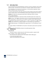
1.1 Introduction
The IFC-BOX2600 fanless Embedded Box Computer is an ideal, application-ready system
platform solution. All electronics are protected in a compact, sealed, aluminum case for
easy embedding in the customer’s own housing, or as a stand-alone application where
space is limited and the environment harsh.
The solid, sealed aluminum case offers vibration and dust resistance while also providing a
passive cooling solution. The IFC-BOX2600 provides system integrators with a turn key
solution
and versatile application development path without breaking the bank or missing
time-to-market deadlines.
IFC-BOX2600 is designed as a palm-size fanless embedded system and occupies only
205
127 x 56.5 mm . The rugged, cast aluminum case not only provides great protection from
EMI, shock/vibration, cold and heat, but also passive cooling for quiet, fanless operation.
IFC-BOX2600 meets demands by offering up to 1 x VGA, 2 x Giga LAN, 4 x USB 2.0 ports,
and
x COM
8 ports all packed into a compact rugged unit and powered by an Intel® Atom™
N2600/ N2800 processor. IFC-BOX2600 also supports both 2.5” SATA HDD and C-FAST
SSD
for storage. Besides, IFC-BOX2600 is a low-power-consumption system and it is powered
by DC
9-36V input. The IFC-BOX2600 provides for diversified application fields.
1.2 Features
Key features
Extremely compact, sealed construction with fanless operation, supports Intel®
Atom™ N2600 1.6 GHz / N2800 1.86 GHz CPU
Ultra slim palm-size system with 2.5" SATA HDD/C-FAST SSD support
Low power consumption system
Support VESA/desk/DIN-rail mountings
IFC-BOX2600 User Manual
2
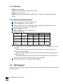
1.3 Specifications
1.3.1 General
CPU: Intel® Atom™ Dual Core Processor N2600 1.6 GHz/N2800 1.86 GHz
System Chipset: Intel® NM10 Express Chipset
BIOS: AMI 16 Mbit Flash BIOS
System Memory: On board 2GByte DDR3 1066GHz SDRAM
Watchdog Timer: 255-level interval timer, setup by software
Serial Ports:
— 2 RS-232/485 BIOS select, support RS-485 auto flow control and TI ISO7221C 4 kV
isolation protection
— 6 RS232 port (ESD protection: air gap ±15 kV, contact ±8 kV), 4KV Surge
protection(only TX/RX)
USB:
— 4 x USB 2.0 compliant Ports
Audio: High Definition Audio Codec - Realtek ALC662, with Line-in, Line-out
Expansion Interface: Support up to 1 x full size Mini-PCIe
Storage:
— Support C-FAST SSD device
— SATA: Support 1 x 2.5” SATAII HDD
1.3.2 Integrated Graphics Controller
Contains Intel graphics processing GMA3600 core
Directx 10.1 compliant Pixel Shader* V3.0 and OGL 3.0
400 MHz( N2600/N2650) graphic core frequency
Video RAM shared with system memory
Display ports: VGA output
VGA: analog RGB display output up to resolution 1920 x 1200 @ 60Hz for N2000
serial
The Intel® Atom™ Processor N2000 series supports full MPEG2 (VLD/ iDCT/MC),
WMV, Fast video Composing, HW decode/ acceleration for MPEG4 Part 10
(AVC/H.264) & VC-1; 720p60, 1080i60, 1080p@24 up to 20 Mps
MPEG4 part2 does not utilize Next Generation Intel® Atom™ Processor based
(Desktop and Mobile) Platform H/W
Hardware Decode assist for Flash Decode for Adobe 11.0 and newer versions
IFC-BOX2600 User Manual
3
1.3.3 Ethernet
Chipset: Intel® 82583V
Speed: 10/100/1000 Mbps, support Wake on LAN
Interface: Up to 2 x RJ45
Standard: Compliant with IEEE 802.3, IEEE 802.3u, IEEE 802.3x, IEEE 8023y,IEEE
802.ab.
1.3.4 Electrical Specifications
Power supply type: AT / ATX jumper select
Power management: ACPI 3.0, APM
Power requirement: +9V-36V DC Wide range voltage input. Support power input
reverse direction protection, recoverable fuse.
Input Voltage: DC 9-36V
Power Adapter: AC to DC 12V/5A, 60W
Power consumption:
N2800(Fanless)
Voltage
Mode
Current Power
N2600(Fanless)
Current
Power
Idle mode
+12V
0.94
10.92
0.74
8.88
Power on
+12V
1.21
14.52
1.09
13.08
Max load
+12V
1.23
14.76
0.88
10.56
Power consumption test conditions:
— Test conditions: Windows®XP Professional, Burntest ver5.3,RENICE X1 C-FAST
16G SSD
— Idle mode: Measure the current value when system is on windows mode and
without running any program
— Power on - Boot: Measure the maximum current value between system power on
and boot-up to OS
— Max load: Measure the maximum current value when system is under maximum
load (CPU with top speed, RAM & Graphic with full loading)
RTC battery: Lithium 3 .3V/210mAH CR2032 battery
1.4 OS Support
It supports Win7, Win XP(Not support 3D and Media Hardware Decode), Win CE 6.0, and Linux
Ubuntu 10.04 UP
IFC-BOX2600 User Manual
4
1.5 OTHER
Deep sleep S4 mode
Reset/Power bottom/Power LED/HDD LED/Com state LED
12-bit programmable GPIO (General Purpose Input/Output) with 3.3V tolerance
Watchdog Timer: Output system reset, programmable counter from 1-255 min/sec
Security data area: 64 bytes on EEPROM for customer saving sensitive data
1.6 Environmental Specifications
Operating temperature:
-20 ~ 60° C (With extended temperature SSD/C-Fast devices)
0 ~50° C (With N2600 CPU and standard temperature HDD/SSD/C-Fast devices)
0 ~45° C (With N2800 CPU and standard temperature HDD/SSD/C-Fast devices)
Relative humidity: 95% @ 40°C (non-condensing)
Storage temperature: -40 ~ 85°C (-40 ~ 185°F)
Vibration loading during operation:
— With SSD/C-FAST: 3 Grms, IEC 60068-2-64, random, 5 ~ 500 Hz, 1 hr/axis
— Shock during operation:
— With C-FAST SSD 30 G, IEC 60068-2-64, half sine, 11 ms duration
Safety: UL,CB,CCC
EMC: CE, FCC Class A
IFC-BOX2600 User Manual
5
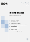
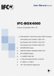
1.7 Mechanical Specifications
IFC-BOX2600 User Manual
6
Figure 1.7 IFC-BOX2600 mechanical dimension drawing
IFC-BOX2600 User Manual
7
Chapter
2
H/W Installation
This chapter explains the setup
procedures of the IFC-BOX2600
hardware, including instructions
on setting jumpers and
connecting peripherals,
switches and indicators. Be
sure to read all safety
precautions before you begin
the installation procedure.
IFC-BOX2600 User Manual
8
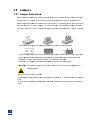
2.1
1 Jum
mpers
2.1
1.1 Jum
mper Des
scription
n
Cards can
n be configu
ured by setting jumpers
s. A jumper is a metal b
bridge used
d to close an
n
electric cirrcuit. It conssists of two metal pins and a smalll metal clip (often prote
ected by a
plastic covver) that slid
des over the
e pins to connect them. To close a jumper, yo
ou connect the
pins with the
t clip. To open a jum
mper, you remove the clip.
c
Sometim
mes a jump
per will have
e
three pins, labeled 1, 2 and 3. In
n this case you
y would connect
c
eith
her pins 1 and 2, or 2 and
a
3.
The jum
mper setting
gs are schem
matically de
epicted in th
his manual a
as follows.
A pair off needle-no
ose pliers may be helpfful when wo
orking with jumpers. If you
y have an
ny
doubts about
a
the be
est hardwarre configura
ation for you
ur applicatio
on, contact your local
distributtor or sales representative before you make any
a change
es.
Generallly, you simp
ply need a standard
s
ca
able to make most connections.
Warning
g! To avoid
d damaging the computter, always turn off the power supply
p before
setting jumpers.
j
How to verify
v
Pin1 of
o the jumpe
er?
1. Please
e check the
e M/B carefu
ully, where there
t
is a mark
m
of “1” o
or white thic
ck line, there
e is
Pin1.
2. Look into the pad
d on the bacck side of th
he M/B, generally the square side of the pad is
i
Pin1.
9
2.1
1.2 Jum
mper Settting
JVDD1
LVDS LC
CD Working
g Voltage Select
S
Part Numb
ber
Description
n
PinHead
der 2x2Pin 2.0mm
2
DIP & Jumper 2
2.0mm
Setting
Functio
on
(1-2)
+3.3V(D
Default)
(3-4)
+5V
The opera
ating voltag
ge of LCD in
n the marke
et are generrally 3.3V an
nd 5V, so please
read the LCD
L
Datash
heet carefully before se
etting right operating
o
vvoltage, othe
erwise
the LCD panel
p
may be
b burned or
o not work normally. Any
A damage
e result from
m this is
NOT cove
ered in free warranty ra
ange.
JVDD2
DI Working Voltage
e Select
Part Numb
ber
Description
n
PinHead
der 2x2Pin 2.0mm
2
DIP & Jumper 2
2.0mm
Setting
Functio
on
(1-2)
+5V(Deffault)
(3-4)
+12V
Pin1 of DI connectorr working vo
oltage selec
ct,max 1A
JVDD3
DO Worrking Voltage Select
Part Numb
ber
Description
n
PinHead
der 2x2Pin 2.0mm
2
DIP & Jumper 2
2.0mm
Setting
Functio
on
(1-2)
+5V(Deffault)
(3-4)
+12V
Pin1 of DO connecto
or working voltage
v
sele
ect,max 1A
`
10
JCMOS_A
AT1
CMOS
S Clear/AT & ATX Pow
wer Mode Se
elect
Part Numb
ber
Description
n
Settting
(3
3-4)
(1-2)
PinHea
ader 2x2Pin
n 2.0mm DIP & Jumper 2.0mm
Funct
OFF
K
KEEP
CMO
OS(Default)
ON
C
CLEAR
CMOS
ON
A
ATX
(Default)
OFF
A
AT
How to clear
c
CMOS
S: (Must folllow steps as below)
If any of these statess happens: such as CM
MOS data co
orruption, a
administrato
or or
password
d of the BIOS forgotten, not able to
o boot-up du
ue to wrong
g setting of the
t CPU
frequencyy in BIOS, or
o the CPU/Memory ne
eed to clear the CMOS setting, the
en you
can use th
his jumper to
t clear CM
MOS, and BIIOS will resset to defaullt settings.
• Pin
n1 and Pin2
2 short circu
uit (default): Normal Co
ondition;
• Pin
n2 and Pin3
3 short circu
uit: Clear CM
MOS setting
g;
Clear CM
MOS setting and load de
efault settin
ngs:
1. Turn-offf the system
m power;
2. Use jum
mper to make Pin2 and
d Pin3 shortt circuit, waiting for 3-5
5sec., then reset
r
the
jumper ass Pin1 and Pin2
P
short circuit.
c
3. Turn-on
n the system
m power
4. If it is th
he wrong se
etting of CP
PU frequenc
cy in BIOS, then please
e press F2 to
t enter
BIOS settting menu once
o
the sysstem reboot.
5. Set the
e CPU opera
ating speed
d to default value or a reasonable
r
value;
6. Save & Exit the BIIOS menu.
Power Mode Selectt:
AT power mode: Bo
oot-up auto
omatically when pow
wer-on.
11
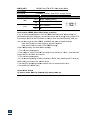
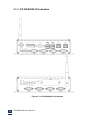
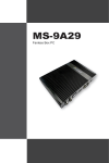
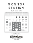
2.1.3 IFC-BOX2600 I/O Indication
Figure 2.1.3 IFC-BOX2600 I/O Indication
IFC-BOX2600 User Manual
12
2.2 External I/O Connectors & Pin Assignments
Power Input Connector
Part Number
Description
(PWR1)
Terminal MB1.5/VF3.5/2-G 2Pin 3.5mm 90° Green DIP
Pin
Signal
Pin
Signal
1
GND
2
DC
IFC-BOX2600 comes with a 3.5mm Phoenix header that carries 9-36VDC external power
input,
inappropriate connection(inverted connection)of the power will burn the M/B. The bracket
makes the power connector very secure.
DI (DI1)
Part Number
Description
Pin
1
3
5
7
GPIO Pin-Header
Terminal MB1.5/V3.5/8-G 8Pin 3.5mm 90° Green DIP
Signal
VCC(5/12V Option)
GPI10
GPI13
GPI22
Pin
2
4
6
8
Signal
GPI9
GPI12
GPI14
GND
1. User can refer to our example for GPI setting. When it is defined as "input", it can receive 3.3V
or 5V level signal.
2. User can select Pin1 5/12V@1A output by jumper JVDD2
IFC-BOX2600 User Manual
13
DO (D01)
Part Numb
ber
Description
n
Pin
1
3
5
7
Signal
S
V
VCC
G
GPO10
G
GPO13
G
GPO22
GPIO Pin-Head
der
Term
minal MB1.5//V3.5/8-G 8Pin
8
3.5mm
m 90° Green DIP
Pin
P
2
4
6
8
Signal
GPO
O9
GPO
O12
GPO
O14
GND
1. User r can refer to
o our example for GPO se
etting. When
n it is defined
d as "output"", it can outp
put
5V@24mA level signa.
2. User can
c select Pin
n1 5/12V@1A output by jumper JVDD3
VGA (VGA
A1)
Part Numb
ber
Description
n
Pin
1
3
5
7
9
11
13
15
Signal
S
R
RED
B
BLUE
G
GND
G
GND
N
NC
N
NC
H
HSYNC
D
DCLK
VG
GA Port with Back I/O Panel
VG
GA Port D-S
Sub 15Pin Female
F
DIP
P
Pin
P
2
4
6
8
10
12
14
Signal
GREEN
NC
GND
GND
GND
DAT
TA
VSY
YNC
VGA: ana
alog RGB display outpu
ut up to resolution 1920 x 1200 @ 60Hz
14
USB1,USB
B2
Part Numb
ber
Description
n
Pin
1
3
5
7
9
11
1.
2.
3.
Do
ouble USB Port
P AF90° 12Pin DIP
Signal
S
U
USB1_VCC
U
USB_DAT+
U
USB1_VCC
U
USB_DAT+
C
CHASSIS
C
CHASSIS
Pin
P
2
4
6
8
10
12
SIM
M Card Soc
cket
SIM
M Card Soc
cket Clamsh
hell-Type 2xx3Pin SMD
Signal
S
S
SIM_PWR
S
SIM_CLK
S
SIM_VPP
Support 3G
3 UIM card
d,Pop-up ho
older
15
Signal
USB
B_DATAGND
USB
B_DATAGND
CHA
ASSIS
CHA
ASSIS
Proviides four US
SB (Universsal Serial Bus)
B
2.0 Porrts Plug and
d Play . The
e USB interrface
comp
plies with high speed USB
U
specific
cation Rev. 2.0 which ssupPorts 48
80 Mbps tran
nsfer
rate, and are fusse protected
d.
The USB
U
interfa
ace can be disabled
d
in the
t system BIOS setup
p.
To better
b
meet our clien
nts’ applica
ation, +5V doesn’t d
do limited 500mA current
prote
ection, so evvery USB output can satisfy max. 1A current demand.
SIM1
Part Numb
ber
Description
n
Pin
1
3
5
US
SB2.0/1.1 Port
P with Bacck I/O pane
el
Pin
P
2
4
6
Signal
SIM
M_RST#
GND
SIM
M_DATA
LAN1,LAN
N2
Part Numb
ber
Description
n
Pin
1
3
5
7
9
11
13
15
17
19
R
RJ45
Port wiith Back I/O
O panel
RJJ45 Port witth Active/lin
nk state LED
D
Signal
S
G
GND
L
LAN1_MDI0
0N
L
LAN1_MDI1
1N
L
LAN1_MDI2
2N
L
LAN1_MDI3
3N
+
+3.3V_LAN
1
L
LAN1_ACT#
#
C
CHASSIS
N
NC
LAN21V9)
L
LAN1TCT(L
Pin
P
2
4
6
8
10
12
14
16
18
20
2
Signal
LAN
N1_MDI0P
LAN
N1_MDI1P
LAN
N1_MDI2P
LAN
N1_MDI3P
CHA
ASSIS
LAN
N1_LINK#
+3.3
3V_LAN1
CHA
ASSIS
NC
LAN
N1TCTG
IFC-BOX2600
p
provides
on
ne RJ45 LAN interface connector which
w
is fully complian
nt with IEEE
E
802.3u 10
0/100/1000 Mbps CSM
MA/CD stand
dards. It is equipped
e
w
with 82583V
V and suppo
ort
Wake on LAN. The Ethernet
E
po
ort uses a sttandard RJ--45 jack con
nnector with
h LED indica
ators
on the fro
ont side to show
s
Active
e/Link status
s and Speed
d status Inte
el 82583V PCI-E
P
10/100/10
000 Mb/s Ethernet, sup
porting wak
ke on LAN and
a PXE.
COM1
Part Numb
ber
Description
n
Pin
1
3
5
7
9
Signal
S
N
NNDCD1#
N
NTX1
G
GND
N
NRTS1#
N
NNRI1#
DB9 COM Porrt with Backk I/O Panel
CO
OM Port D-S
Sub 9Pin Ma
ale DIP
Pin
P
2
4
6
8
Signal
NRX
X1
NDT
TR1#
NDS
SR1#
NCT
TS1#
1. RS23
32 RX/TX sig
gnal support 4KV surg
ge protection
n;
2. Max. traffic rate: 115200bpss
16
COM3,COM4
Part Number
Description
Pin
1
3
5
7
9
Signal
NNDCD1#_485#
NTX1
GND
NC
NC
DB9 COM Port with Back I/O Panel
COM Port D-Sub 9Pin Male DIP
Pin
2
4
6
8
Signal
NRX1_485
NC
NC
NC
1. By BIOS setup RS232/485;
2. When select RS485, then Pin1 & Pin2 are RS485 output, support 4KV electromagnetic
isolation and automatically data flow control.
3. Olny RX/TX/GND 3 line RS232 port
4. Olny RX/TX/GND 3 line RS232 signal support 4KV surge protection;
5. Max. traffic rate: 115200bps
COM2,COM5~COM8
Part Number
Description
Pin
1
3
5
7
9
Signal
NC
NTX1
GND
NC
NC
DB9 COM Port with Back I/O Panel
COM Port D-Sub 9Pin Male DIP
Pin
2
4
6
8
Signal
NRX1
NC
NC
NC
1. Olny RX/TX/GND 3 line RS232 port
2. RS232 RX/TX signal support 4KV surge protection;
3. Max. traffic rate: 115200bps
IFC-BOX2600 User Manual
17
AUDIO (AUDIO1)
Part Number
Description
AUDIO Connector
AUDIO Jack Green Vertical 5Pin DIP
Pin
Signal
Pin
Signal
IFC-BOX2600 offers stereo audio ports by two 3.5 ear phone jack connectors of Line_out and
Line_in. The audio chip controller is ALC892 which is compliant with the Azalea standard.
MIC (MIC1)
Part Number
Description
MIC Connector
MIC Jack Green Vertical 5Pin DIP
Pin
Signal
Pin
Signal
IFC-BOX2600 offers stereo audio ports by two 3.5 ear phone jack connectors of Line_out and
Line_in. The audio chip controller is ALC662 which is compliant with the Azalea standard.
Com_LED
Part Number
Description
Pin
Signal
(LED1,LED2,LED3,LED4,LED5)
LED Group 2Row Green DIP-4P
Pin
Signal
The LED is blinking when COM1-COM8 is transferring data; Vice versa.
IFC-BOX2600 User Manual
18
Power ON
N/OFF Butto
on
Part Numb
ber
Description
n
(P
PWR_SW1))
P
Power
Butto
on LED PTC
CT-07-A 5P
P 7Pin DIP
IFC-BOX2600
o
omes
c with a Power On
n/Off button with LED in
ndicators on
n the front side
s
to show
w its
On status (G
Green LED) and
a Off/Susp
pend status (Orange LED
D). Dual funcctions of Softt Power -On//Off
(Instant off or
o Delay 4 Se
econds), and
d Suspend are supported
d.
Reset Buttton
Part Numb
ber
Description
n
(S
SW2)
P
Power
Butto
on DTSA-64
44 4Pin DIP
P
IFC-BOX2600
o
omes
c with a RESET bu
utton.
AST (CFAS
ST1)
CFA
Part Numb
ber
Description
n
Pin
1
3
5
7
9
11
13
15
17
19
21
23
Compa
actFlash Ty
ypeII Socke
et
CF Socket CFAHU-SSC
C
C1-110-0040 24Pin 1.2
27mm SMD
Signal
S
G
GND
T
TXR
RX+
G
GND
G
GND
T
TBD
T
TBD
IO
O11
IO
O1
IO
O3
V
VCC33
P
PGND
Standard C-FAST SA
ATAII socke
et
19
Pin
P
2
4
6
8
10
12
14
16
18
20
2
22
2
24
2
Signal
TX+
+
GND
RX-CDII
TBD
D
TBD
D
GND
IO12
IO2
VCC
C33
PGN
ND
CDO
O
MINI-PCIE1
Part Number
Description
Pin
1
3
5
7
9
11
13
15
17
19
21
23
25
27
29
31
33
35
37
39
41
43
45
47
49
51
Signal
WAKE#
RSVD1
RSVD2
CLKREQ#
CND1
REFCLKREFCLK+
CND2
RSVD3
RSVD4
CND3
PER_N0
PER_P0
CND4
CND5
PET_N0
PET_P0
CND6
RSVD5
RSVD6
RSVD7
RSVD8
RSVD9
RSVD10
RSVD11
RSVD12
Mini-PCIe Connector
Mini-PCIe Slot SD-8003-402 52Pin H6.7mm SMD
Pin
2
4
6
8
10
12
14
16
18
20
22
24
26
28
30
32
34
36
38
40
42
44
46
48
50
52
Signal
+3.3V_1
CND7
+1.5V_1
SIM_PWR
SIM_DATA
SIM_CLK
SIM_RST#
SIM_VPP
CND8
W_DISABLE#
PERST#
+3.3V_AUX
CND9
+1.5V_2
SMB_CLK
SMB_DATA
CND10
USB_DUSB_D+
CND11
LED_WWAN#
LED_WLAN#
LED_WPAN#
+1.5V_3
CND12
+3.3V_2
Support PCI Express x1 bus Mini PCIE and USB device.
IFC-BOX2600 User Manual
20
2.3 Peripheral Installation
2.3.1 HDD Installation (IFC-BOX2600 only)
1.
Unscrew the bottom cover screws. (marked with "HDD")
IFC-BOX2600 User Manual
21
Chapter
3
BIOS Settings
IFC-BOX2600 User Manual
22
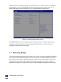
AMIBIOS has been integrated into many motherboards for over a decade. With the AMIBIOS
Setup program, you can modify BIOS settings and control the various system features. Thi
chapter describes the basic navigation of the IFC-BOX2600 BIOS setup screens.
Figure 3.1 Setup Program Initial Screen
AMI's BIOS ROM has a built-in Setup program that allows users to modify the basic system
configuration. This information is stored in battery-backed CMOS so it retains the Setup
information when the power is turned off.
3.1 Entering Setup
Turn on the computer and check for the “patch" code. If there is a number assigned to the patch
code, it means that the BIOS supports your CPU. If there is no number assigned to the patch
code, please contact an IFC application engineer to obtain an up-to-date patch code file. This
will ensure that your CPU's system status is valid. After ensuring that you have a number
assigned to the patch code, press <DEL> and you will immediately be allowed to enter Setup.
IFC-BOX2600 User Manual
23
3.2 Main Setup
When you first enter the BIOS Setup Utility, you will enter the Main setup screen. You can
always return to the Main setup screen by selecting the Main tab. There are two Main Setup
options. They are described in this section. The Main BIOS Setup screen is shown below.
Figure 3.2 Main Setup Screen
The Main BIOS setup screen has two main frames. The left frame displays all the options that
can be configured. Grayed-out options cannot be configured; options in blue can. The right
frame displays the key legend.
Above the key legend is an area reserved for a text message. When an option is selected in the
left frame, it is highlighted in white. Often a text message will accompany it.
3.2.1 System Time / System Date
Use this option to change the system time and date. Highlight System Time or System Date
using the <Arrow> keys. Enter new values through the keyboard. Press the <Tab> key or the
<Arrow> keys to move between fields. The date must be entered in MM/DD/YY format. The
time must be entered in HH:MM:SS format.
IFC-BOX2600 User Manual
24
3.3 Advanced BIOS Features Setup
Select the Advanced tab from the IFC-BOX2600 setup screen to enter the Advanced BIOS Setup
screen. You can select any of the items in the left frame of the screen, such as CPU
Configuration, to go to the sub menu for that item. You can display an Advanced BIOS Setup
option by highlighting it using the <Arrow> keys. All Advanced BIOS Setup options are
described in this section. The Advanced BIOS Setup screens is shown below. The sub menus
are described on the following pages.
Figure 3.3 Advanced BIOS Features Setup Screen
IFC-BOX2600 User Manual
25
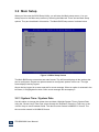
3.3.1 PCI Subsystem Setting
Figure 3.3.1 PCI Subsystem Configuration Setting
IFC-BOX2600 User Manual
26
3.3.2 ACPI Setting
Figure 3.3.2 ACPI Configuration Setting
IFC-BOX2600 User Manual
27
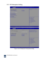
3.3.3 CPU Configuration Setting
Figure 3.3.3 CPU Configuration Setting
Max CPUID Value Limit
This item allows you to limit CPUID maximum value.
Execute-Disable Bit Capability
This item allows you to enable or disable the No-Execution page protection technology.
IFC-BOX2600 User Manual
28
Hyper Threading Technology
This item allows you to enable or disable Intel Hyper Threading technology.
3.3.4 SATA Configuration
Figure 3.3.4 SATA Configuration
SATA E Configuration
This item allows you to select Disabled / IDE / AHCI
IFC-BOX2600 User Manual
29
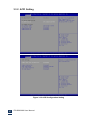
3.3.5 USB Configuration
Figure 3.3.5 USB Configuration
IFC-BOX2600 User Manual
30
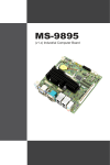
3.3.6 Super I/O Configuration
IFC-BOX2600 User Manual
31
IFC-BOX2600 User Manual
32
Figure 3.3.6 Super I/O Configuration
Serial Port1- Port8 address
This item allows you to select serial port1 ~ port8 of base addresses.
Serial Port1- Port8 IRQ
This item allows you to select serial port1 ~ port8 of IRQ.
Com3-Com4 RS232/RS485 Select
This item allows you to select Com3-Com4 RS232/RS485 model
IFC-BOX2600 User Manual
33
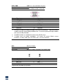
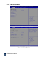
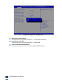
3.3.7 PC Health Status
Figure 3.3.7 PC Health status
IFC-BOX2600 User Manual
34
IFC-BOX2600 User Manual
35
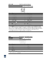
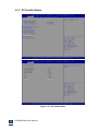
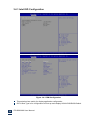
3.3.8 PPM Configuration
Figure 3.3.8 PPM Configuration
IFC-BOX2600 User Manual
36
EIST
When configuration is “Enabled”, the M/B will auto-adjust operation frequency according to
current CPU operation status, for power saving consideration.
This selection item also support the configuration of CPU sleep state, support max.
Intel C6 mode.
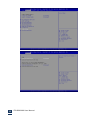
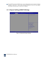
3.4 Chipset Settings/HOST Bridge
Figure 3.4 Advanced Chipset Settings
IFC-BOX2600 User Manual
37
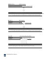
3.4.1 Intel IGD Configuration
Figure 3.4.1 PPM Configuration
This selection item mainly for display application configuration.
IGFX--Boot Type is for configuration of boot-up main display:VGA/LVDS/VBIOS Default.
IFC-BOX2600 User Manual
38
During POST process and DOS mode, only one display device can be chosen for display,
otherwise, it won’t work; And only after entering to Windows or Linux OS, it can support
dual display (simultaneously or asynchronous display).
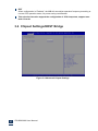
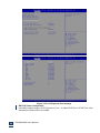
3.5 Chipset Settings/SOUTH Bridge
Figure 3.5 Advanced Chipset Settings
IFC-BOX2600 User Manual
39
3.5.1 NM10 Chip Configuration
Figure 3.5.1 NM10 Chip Settings
This selection item is for Audio/NM10 Chip integrated network card /SMBus
configuration.
IFC-BOX2600 User Manual
40
LAN controller
IFC-BOX2600 does Not apply Intel NM10 chipset built-in Intel 82567V LAN controller,
so
default
the setting is “Disabled”.
SMBUS Controller
Enables or disables the SMBUS controller.
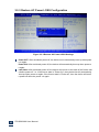
3.5.2 PCI Expresss Port 0-Port 4 Configuration
IFC-BOX2600 User Manual
41
IFC-BOX2600 User Manual
42
IFC-BOX2600 User Manual
43
Figure 3.5.2 PCI Expresss Port Settings
SB PCIE Ports Configuration
Intel NM10 chipset support 4 PCI Express x 1 bus,in which PCIE Port 1和PCIE Port 2 are
allocated to onboard LAN1 and LAN2
IFC-BOX2600 User Manual
44
3.5.3 Restore AC Power LOSS Configuration
Figure 3.5.3 Restore AC Power LOSS Settings
Power OFF: After accidental power-off, the device won't automatically boot-up when powe
r-on again.
Power ON: After accidental power-off, the device will automatically boot-up when power-o
n again.
Last State: After accidental power-off, the device will recover to the state of the former stat
e before power-off. i.e.: If the former state is "Power On", then the device will automatically
boot-up when power-on again; if the former state is "Power off", then the device will remai
n power-off when the power- on again.
IFC-BOX2600 User Manual
45
3.5.4 BOOT Configuration
Figure 3.5.4 BOOT Configuration
IFC-BOX2600 User Manual
46
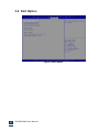
3.6 Exit Option
Figure 3.6 Exit Option
IFC-BOX2600 User Manual
47
Save Changes and Exit
When you have completed system configuration, select this option to save your changes, exit
BIOS setup and reboot the computer so the new system configuration parameters can take
effect.
1. Select Exit Saving Changes from the Exit menu and press <Enter>. The following message
appears: Save Configuration Changes and Exit Now? [Ok] [Cancel]
2. Select Ok or cancel.
3.6.1. Discard Changes and Exit
Select this option to quit Setup without making any permanent changes to the system
configuration.
1. Select Exit Discarding Changes from the Exit menu and press <Enter>. The following
message appears: Discard Changes and Exit Setup Now? [Ok] [Cancel]
1. Select Ok to discard changes and exit. Discard Changes
2. Select Discard Changes from the Exit menu and press <Enter>.
3.6.2. Load Optimal Defaults
The IFC-BOX2600 automatically configures all setup items to optimal settings when you select this
option. Optimal Defaults are designed for maximum system performance, but may not work
best for all computer applications. In particular, do not use the Optimal Defaults if your computer
is experiencing system configuration problems. Select Load Optimal Defaults from the Exit
menu and press <Enter>.
3.6.3. Load Fail-Safe Defaults
The IFC-BOX2600 automatically configures all setup options to fail-safe settings when you select this
option. Fail-Safe Defaults are designed for maximum system stability, but not maximum
performance. Select Fail-Safe Defaults if your computer is experiencing system configuration
problems.
1. Select Load Fail-Safe Defaults from the Exit menu and press <Enter>. The following
message appears: Load Fail-Safe Defaults? [OK] [Cancel]
2. Select OK to load Fail-Safe defaults.
IFC-BOX2600 User Manual
48
Chapter
4
S/W Introduction & Installation
IFC-BOX2600 User Manual
49
4.1 S/W Introduction
Szics provides all the drivers and services as bellow to ensure fast and smooth
accomplishment of clients’ project:
Drivers for Windows®XP Professional, Windows7, Linux
Windows®XP Embedded tailor service;
Watchdog program example
GPIO program example
BIOS upgrade burning and curing service
4.2 Driver Install
There is a driver CD with the IFC-BOX2600 accessory, and all the driver programs are in it,
please install the drivers and application programs after the OS installation to ensure
the M/B can fully play the great performance. If you are using the upgraded version, we
suggest to remove all the drivers and application programs of the old version before
installing the new version. For more detailed information, please consult the H/W
supplier.
4.2.1 Windows®XP Professional Driver Install
Step1: Install Chipset driver, open Intel_Chipset_WinXP_infinst_autol folder, double click
Setup to install
Step2: Install Graphics driver, double click EMGD_CDV_1_15_1_GC_3278.exe to install
Step3: Install audio driver, open Realtek_WDM_R270_WinX folder, double click Setup to
install
Step4: Install LAN driver, double click Intel 82583v_PRO2K3XP_32.exe to install
REMARK:
The display driver for Windows®XP Professional is tailored by using the software
tool of Intel EMGD, and this driver program does NOT support 3D and media
acceleration function.
4.2.2 Windows® 7 Driver Install
Step1: Install Chipset driver, open Intel_Chipset_Win7_infinst_autol folder, double click Setup
Step2: Install Graphics driver,double click Intel GMA3600_Win7_32_8.14.8.1083_PV.exe
Step3: Install audio driver, double click Vista_Win7_Win8_R270.zip
Step4: Install LAN driver, double click Intel 82583v_PRO2K3XP_32.exe to install
IFC-BOX2600 User Manual
50
4.2.3 Windows Driver Upgrade
Chip manufacturers association regularly to upgrade its corresponding product drive, the user
can access through the following links attention or update drive.
Intel Chipset driver upgrade:
http://downloadcenter.intel.com/Detail_Desc.aspx?agr=Y&DwnldID=20775&lang=eng&wa
pkw=nm10
Intel Graphics driver upgrade:
http://downloadcenter.intel.com/Detail_Desc.aspx?agr=Y&DwnldID=21690&lang=eng&OS
Version=Windows%207%20(32-bit)*&DownloadType=Drivers
Reltek HD audio driver upgrade:
http://www.realtek.com.tw/downloads/downloadsView.aspx?Langid=3&PNid=24&PFid=24
&Level=4&Conn=3&DownTypeID=3&GetDown=false
Intel 82583V LAN driver upgrade:
http://downloadcenter.intel.com/SearchResult.aspx?lang=ZHO&ProductFamily=%e4%bb
%a5%e5%a4%aa%e7%bd%91%e7%bb%84%e4%bb%b6&ProductLine=%e4%bb%a5%e5%a
4%aa%e7%bd%91%e6%8e%a7%e5%88%b6%e5%99%a8&ProductProduct=%e8%8b%b1%
e7%89%b9%e5%b0%94%c2%ae+82583V+%e5%8d%83%e5%85%86%e4%bb%a5%e5%a4
%aa%e7%bd%91%e6%8e%a7%e5%88%b6%e5%99%a8&ProdId=3147&LineId=976&FamilyI
d=2280
4.2.4 Linux Driver Install
IFC-BOX2600 provides 2line onboard Intel82583 Giga LAN, since the kernel of Linux OS has not
loaded Intel82583 Driver, so when we run Linux OS, we need set PCIE Port 0 and PCIE Port 1
as Disabled, and enter Linux OS to install Intel82583 Driver, then restart OS and set PCIE Port
0 and PCIE Port 1 as Enabled, only after that the LAN can work normally.(Refer to part 3.5.2 for
PCI Express Configuration)
4.2.5 Linux Driver Upgrade
Chip manufacturers association regularly to upgrade its corresponding product drive, the user
can access through the following links attention or update drive.
Intel Graphics driver upgrade:
https://01.org/linuxgraphics/downloads
Reltek HD audio driver upgrade:
http://www.realtek.com.tw/downloads/downloadsView.aspx?Langid=3&PNid=24&PFid=24
&Level=4&Conn =3&DownTypeID=3&GetDown=false
IFC-BOX2600 User Manual
51
4.3 Windows®XP Embedded Service
IFC provides free service of Windows®XP Embedded tailor service.
4.4 Watchdog program example
A watchdog timer (abbreviated as WDT) is a hardware device which triggers an action,
e.g. rebooting the system, if the system does not reset the timer within a specific period
of time. The WDT program example provides developers with functions such as starting
the timer, resetting the timer, and setting the timeout value if the hardware requires
customized timeout values.
Please contact our service personnel for program example source code and packaging
EXE executable file.
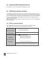
4.4.1 WDT Programming Model
WDT related registers, generally there are two frequently-used registers named as
“WDT_TIME_OUT” and “WDT_VAL”, detailed descriptions refer to bellow:
WDT_TME_OUT
(I/O address 0x665,
Default 0x00)
Bit7: WDT countdown mode selection:
0: to countdown with minute;
1: to countdown with second;
Bit [6:0]: Reserved bit, keep it as default value.
Bit [7:0]
WDT_VAL
0x00: Stop countdown;
0x01: time-out value 1min./sec.;
0x02: time-out value 2min./sec.;
0x03: time-out value 3min./sec.;
......
(I/O address 0x666,
0xFF: time-out value 255min./sec.;
Default 0x00)
This register is used for WDT time-out-value setting, write in a
nonzero value, then WDT begins to countdown from this value.
IFC-BOX2600 User Manual
52
Refer to routine “WDT.C”.
#include <stdio.h>
#include <dos.h>
void main()
{
int value=0; int unit=0;
printf("please input value (1~255) : ");
scanf("%d",&value);
printf("please input unit 0/1(0=seconds,1=minutes) : ");
scanf("%d",&unit);
outportb(0x647,0x0c);
if(unit==0)
{outportb(0x665,0x80);}
else
{outportb(0x665,0x00);}
outportb(0x666,value);
}
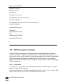
4.5 GPIO program example
General Purpose Input/Output is a flexible parallel interface that allows a variety of
custom connections. It allows users to monitor the level of signal input or set the output status to switch on/off a device. Our program example also provides Programmable
GPIO, which allows developers to dynamically set the GPIO input or output status.
Please contact our service personnel for program example source code and packaging
EXE executable file.
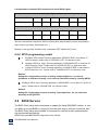
4.5.1 Overview
This instruction is only applied to the CMS-B802 Motherboard with NM10 chipset. Altogether
there are 12 sets GPIO on this M/B.
The level of input/output of all those 12 sets GPIO(GP9、GP10、GP12、GP13、GP14、GP22、
GP28、GP33、GP34、GP36、GP38、GP39)are designed as 5VTTL.
IFC-BOX2600 User Manual
53
Correspondence between GPIO interface and actual GPIO signal:
Output Type
Interface S/N
1
2
3
4
5
6
GPIO Signal
GP28
GP33
GP34
GP36
GP38
GP39
Iutput Type
Interface S/N
1
2
3
4
5
6
GPIO Signal
GP9
GP10
GP12
GP13
GP14
GP22
We don’t recommend using those GPIO to directly drive devices which require comparatively
large current (eg. Relay, Optocoupler etc.. )
Besides, it also provides a 255sec./min. countdown WDT (Watch Dog Timer).
4.5.2 GPIO programming model
A.
Configure GPIO Output: Running application “GPIOOUT.EXE” to set these 12
GPIO as output. Please refer to “GPIOOUT.CPP” for reference code.
B. Configure GPIO as “High”: Running application “HIGHGPIO.EXE” to set these 12
GPIO output as “High”. Please refer to “HIGHGPIO.CPP” for reference code.
C. Configure GPIO as “Low”: Running application “LOWGPIO.EXE” to set these 12
GPIO output as “Low”. Please refer to “LOWGPIO.CPP” for reference code.
Remark:
During the configuration process of setting “Output High/Low”, we can use
multimeter or indicator to testify, or we can also check the status by running GETIO.
Configure GPIO Input: Running application “GPIOIN.EXE” to set these 12 GPIO as
“Input”. Please refer to “GPIOIN.CPP” for reference code.
Remark:
During the configuration process of setting “Input High/Low”, we can check the
status by running GETIO.
4.6 BIOS Service
The BIOS Flash utility allows customers to update the flash ROM BIOS version, or use
it to back up current BIOS by copying it from the flash chip to a file on customers’ disk.
The BIOS Flash utility also provides a command line version for fast implementation
into customized applications.
SZICS also provides BIOS curing service for clients.
IFC-BOX2600 User Manual
54
4.6
6.1 BIOS
S Upgra
ade Tool Instruc
ction
The bu
urner can be
b only applied to DOS environme
ent, the userr should pre
epare a boo
ot
disk with
w DOS system before
e BIOS burn
ning processs;
Copy burner “EFIIDOS.EXE” and the BIOS file to th
he root direcctory of the DOS boot
disk;
Conne
ect the DOS
S boot disk to
t the M/B, startup and
d press “DE
EL” to enter CMOS settting
interfa
ace, and sett the DOS boot
b
disk as
s the first bo
oot device in
n “boot”ÆBIOS;
Press F10 to save
e the new setting
s
and reset the syystem;
When the M/B en
nter DOS syystem, and display the drive letter of DOS sys
stem, pleasse
input the
t comman
nd characte
er as bellow
w, and then press
p
“Ente
er” (Assume
e the BIOS file
f
named
d “BIOS.RO
OM”):
EFIDO
OS /IBIOS.R
ROM /pbnc /n
After “Enter”,
“
BIO
OS start to re
efresh, the M/B is not allowed
a
to b
be turned-offf, reset or
powerr-off etc. durring the who
ole refresh process, ottherwise the
e M/B will no
ot be able to
start up
u again. When
W
the BIO
OS burning process is finished, the user can reset the
system
m.
4.6
6.2 BIOS
S LOGO
O Replac
cement Tool
T
Instruction
n
Logo change
c
can
n be directed
d as following steps
Save the
t primary“Splash Log
go”of BIOS
Save the
t primary “Small Log
go” of BIOS
Replacce the primary “Splash
h Logo”of BIOS
Replacce the primary “Small Logo”
L
of BIO
OS
1.
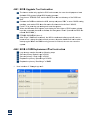
55
User interfface of “Cha
angeLogo.e
exe”:
56
2.
Click “Load
d Image” to
o load the prrimary BIOS
S file.
3.
Select the logo which will be savved from the
e drop-down
n box of “Sp
plash Logo”, then click
“save logo
o” to save th
he logo unde
er a specifie
ed directoryy.
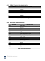
4.
During the
e Logo repla
acement ope
eration, please click “B
Browse” to sselect Logo which is to be
adopted in
n the BIOS, and the ima
age size mu
ust be 800xx600 or 640x480 with BMP
B
formatt:
57
5.
After seleccting the right Logo, clicck “Replace
e Logo”, the
en the Logo replaceme
ent is done:
6.
After clicking “Replace
e Logo”, the
ere will be a message shows up:“ New logo is created”,
,
which mea
ans the new
w Logo is replaced succ
cessfully. If you replace
e“Splash Lo
ogo”, then
n
the new BIIOS Logo will
w be displa
ayed with fu
ull screen affter the systtem reboot; if you
replace“Sm
mall Logo”,
,then the new BIOS Lo
ogo will be displayed
d
o
on the up-lefft corner of the
screen afte
er the syste
em reboot.
7.
Click “Save
e Image AS
S”, to save the
t new BIO
OS under a specified directory.
8.
If it doesn’t display the
e new BIOS
S Logo afterr system reboot, please
e check if th
he setting as
a
bellow is Enable:
E
Boot-->Quiiet Boot-->E
Enable
Chapter
5
Appendix: A
IFC-BOX2600 User Manual
58
A.1 System I/O Ports
Addr.
Range
000-01F
DMA
020-021
Interrupt
040-043
Timer/Counter
060-06F
8042
070-07F
Real-time
080-09F
DMA
0A0-0BF
Interrupt
0C0-0DF
DMA
274-279
ISAPNP read data port
280-287
COM6
288-28F
COM5
290-297
COM7
298-29F
COM8
2E8-2EF
COM4
2F8-2FF
COM2
3B0-3DF
VgaSave
3E8-3EF
COM3
3F8-3FF
COM1
400-4D1
Interrupt
500-77F
Motherboard
A79-A79
ISAPNP read data port
B78-B7F
Motherboard
Table 5.1 System I/O Ports
A.2 1st MB Memory Map
Addr. Range (Hex)
Device
00000000h - 00003FFFh
000A0000h - FEBFFFFFh
Motherboard resources
PCI bus
FEC00000h - FEC00FFFh
Motherboard resources
FED00000h - FED003FFh
High precision event timer
FED14000h - FED19FFFh
System board
FED1C000h - FEE00FFFh
Motherboard resources
FF000000h - FFFFFFFFh
Intel 82802 firmware Hub Device
Table 5.2 1st MB Memory Map
IFC-BOX2600 User Manual
59
A.3 DMA Channel Assignments
Channel
Function
0
1
Available
Available
2
Available
3
Available
4
Direct memory access controller
5
Available
6
Available
7
Available
Table 5.3 DMA Channel Assignments
A.4 Interrupt Assignments
Interrupt#
IRQ0
IRQ1
Interrupt source
IRQ3
System timer
Standard 101/102-Key or Microsoft Natural PS/2
Keyboard
COM2
IRQ4
COM1
IRQ5
COM6
IRQ7
COM5 /SMBus Controller
IRQ8
System CMOS/real time clock
IRQ9
Microsoft ACPI-Compliant System
IRQ10
COM7 /COM8
IRQ11
COM3/COM4
IRQ12
PS/2 compatible mouse
IRQ13
Numeric data processor
IRQ16
Network /USB
IRQ17
Network
IRQ18
USB
IRQ19
SATA
IRQ22
HDA
IRQ23
USB
Table 5.4 Interrupt Assignments
IFC-BOX2600 User Manual
60