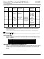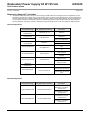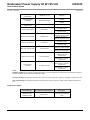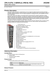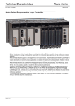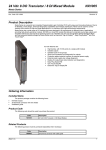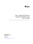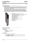
1
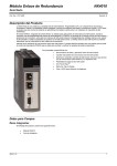
Redundant Power Supply 60 W 125 Vdc HX8320 Série Hadron Xtorm Cód. Doc.: CE123200 Revision: B Product Description Automation of power applications is characterized by the use of rugged and reliable equipment and devices with high technology, capability to operate in hostile environments, where there are significant levels of electromagnetic interference and higher operating temperatures. This is the reality of applications in hydropower plants, power substations and wind farms, among others. In this context, Hadron Xtorm Series is an innovative Remote Terminal Unit (RTU), perfect for applications in power generation, transmission and distribution. The Series has an ideal set of features with high performance for the different stages in the life cycle of any application, like engineering, installation and commissioning, offering cost and risk reduction for every single stage. It also minimizes downtime and system maintenance when in operation. With intuitive and friendly interfaces, accurate and smart diagnostics, modern and robust design, as well as several innovative features, Hadron Xtorm Series surpasses the requirements of applications in this market. The Series has a smart and versatile architecture, offering modularity in input and output (I/O) points, redundancy options, module hot swapping, high-speed communication protocols, such as IEC 61850 and DNP3, logic implementation in accordance to IEC 61131-3 standard and time synchronism. The HX8320 module supplies up to 60 W of power to the other modules of the Hadron Xtorm series through the racks. The module has a 125 Vdc isolated input with an internal protection fuse accessible from its front panel. Due to its internal high efficiency switched power supply, the HX8320 module offers high power output, low noise and immunity to electromagnetic interference (EMC/EMI). In addition, this module has the bus expansion feature, which allows the connection of the main rack with remote input and output racks through two RJ45 ports located on the module front panel. Its main features are: Switched power supply Redundancy operating capacity 60 W output power 125 Vdc input voltage Internal fuse protection Protection against polarity reversal Voltage surge protection Integrated bus expansion function Fan-less design (no moving parts inside) Module diagnostics via graphical display and LEDs Indication of operation through NO dry contact relay Ordering Information Included Items The product package contains the following items: HX8320 Module HX9401 06 pin terminal block Installation guide Product Code The following code should be used to purchase the product: Altus S. A. Code Description HX8320 Redundant Power Supply 60 W 125 Vdc 1 Redundant Power Supply 60 W 125 Vdc HX8320 Série Hadron Xtorm Cód. Doc.: CE123200 Revision: B Related Products The following products must be purchased separately when needed: Code Description NX9202 RJ45-RJ45 2 m Cable NX9205 RJ45-RJ45 5 m Cable NX9210 RJ45-RJ45 10 m Cable Note: NX9202, NX9205 e NX9210: CAT5 Ethernet cable, shielded, twisted pair, RJ45 male connectors on both ends, supports temperature of -5 ºc to 70 ºc, to be used in Ethernet networks, with length of 2, 5 and 10 m, respectively. Innovative Features Hadron Xtorm Series brings to the user several innovations in utilization, supervision and system maintenance. These features were developed focusing a new concept in power plants and substations automation. The list below shows some features that the user will find in Hadron Xtorm module: One Touch Diag: This Hadron Xtorm Series feature allows the user to check diagnostic information of any module present in the system directly on CPU’s graphic display with one single press in the diagnostic switch of the respective module. OTD is a powerful diagnostic tool that can be used offline, reducing maintenance and commissioning times.. ETD – Electronic Tag on Display: This new functionality allows the process of checking the tag names of any I/O terminal or module used in the system directly on the CPU’s graphic display. Along with this information, the user can check the description, as well. This feature is extremely useful during maintenance and troubleshooting procedures. Product Features General Features HX8320 Altus S. A. Nominal input voltage 125 Vdc Maximum output power dissipated 60 W Maximum output current 12 A Input voltage range 100 to 135 Vdc Nominal input current 850 mA @ 100 Vdc Typical efficiency 82% @ 100 Vdc Maximum input voltage interruption time 10 ms @ 100 Vdc Inrush current 5 A @ 125 Vdc Protection fuse 3A Redundancy support Yes Hot swap support Yes One Touch Diag (OTD) Yes Protections Protection against polarity reversal Input short circuit protection with internal fuse Input protection against voltages lower than the minimum input voltage with auto-recovery Isolation Input to output Input to protective earth Input to functional earth 2500 Vac / 1 minute 2500 Vac / 1 minute 2500 Vac / 1 minute Status indication and diagnostics Graphical display LEDs Auxiliary relay 2 Redundant Power Supply 60 W 125 Vdc HX8320 Série Hadron Xtorm Cód. Doc.: CE123200 Revision: B Signaling relay Resistive load: 0.3 A @ 125 Vdc Inductive load: 0.3 A @ 125 Vdc (L/R = 40 ms) Wire gauge 2.5 mm2 IP level IP 20 Operating temperature -5 to 70 °C Storage temperature -20 to 85 °C Relative humidity 5 to 96%. non-condensing Conformal coating Yes Standards IEC 61131-2 CE, Electromagnetic Compatibility (EMC) and Low-Voltage Directive (LVD) Module dimensions (W x H x D) 38.0 x 235.3 x 189.1 mm Package dimensions (W x H x D) 55.0 x 308.0 x 266.0 mm Net weight 1200 g Gross weight 1500 g Notes: Conformal coating: Conformal coating protects the internal parts of the product from moisture, dust and other harsh elements to electronic circuits. Current consumption on the rack power supply: This value must be considered in the calculation of power supply capacity of the rack when using redundant power supplies. One Touch Diag (OTD): This option is available only when the module is in operating mode. Bus Expansion Features HX8320 Ports 2 Connectors RJ45 (shielded female) Bus expansion support with loopback (cabling redundancy) Yes Maximum number of expansion racks 8 racks Maximum number of I/O modules 64 Maximum cable length 100 m Cable type UTP or ScTP, category 5 Baud rate Automatic Physical layer 10/100BASE-T Isolation ….IN to logic ….IN to protective earth ….OUT to logic ….OUT to protective earth 1500 Vac / 1 minute 1500 Vac / 1 minute 1500 Vac / 1 minute 1500 Vac / 1 minute Notes: Time sync to event log: Through the expansion bus function, it is possible to retransmit the CPU time synchronism signal to the digital input modules localized in the remote racks, allowing 1 ms resolution for the event log. Logic: Logic is the name of the internal interfaces as memories, processor and rack interfaces. Altus S. A. 3 Redundant Power Supply 60 W 125 Vdc HX8320 Série Hadron Xtorm Cód. Doc.: CE123200 Revision: B Power Supply Redundancy The Hadron Xtorm series supports redundancy of power supplies installed in the same rack. When an error occurs with any of these power supplies, the second one assumes the total system load. This means that critical processes are not affected by hardware failures in the control system. The result is increased availability and reliability of the system, minimizing downtime and/or stop. Further information about configuration and use of power supply redundancy features are found in the Hadron Xtorm User Manual – MU223100. The figure below shows an example of a power supply redundancy topology. Note: Power Supply redundancy support: In this case the redundant power supply needs to be connected in the in the rack positions 0 and 1. Altus S. A. 4 Redundant Power Supply 60 W 125 Vdc HX8320 Série Hadron Xtorm Cód. Doc.: CE123200 Revision: B System Configurations The suggested configurations for the HX8320 module are shown below: Configuration A: Bus Expansion without Loopback This architecture is based on a main rack (where the CPU is located) and remote racks. The communication between the local and remote racks is made through the extension ports, located on the front panel of the the HX8320 module. Each remote rack requires its own power supply module. The HX8320 module has two RJ45 ports, one being used for the input data and the other one for the output data. In this application example, only the output port of the local HX8320 module is connected, leaving the input data port opened. On the other hand, in the last remote rack, is the output data port that stays open. The intermediate remote racks present both connected ports: a port connected to the previous rack and the other one to the next rack. Each HX8320 module contains two keys to select the rack address, which must be unique. This architecture is designed for medium and large applications with high number of I/O points. Altus S. A. 5 Redundant Power Supply 60 W 125 Vdc HX8320 Série Hadron Xtorm Cód. Doc.: CE123200 Revision: B Configuration B: Bus Expansion with Loopback In the same way, as the previous one, this architecture is based on a local rack (where the CPU is located) and remote racks. The communication between the local and remote racks is made through the extension ports, located in the HX8320 module. The only difference compared to the previous architecture, is that the output data port of the last remote rack is connected to the main rack input data port. This architecture allows the system to maintain access to remote racks information even in the event of a failure in the extension cables. The CPU detects the simple failure in one of the cables and redirects internal data paths to support this failure. In this case, will also be generated a diagnostic alarm for the user. This feature has advantages in the case of cables maintenance with the system energized, in addition to increasing system availability. The figure below illustrates this architecture. Altus S. A. 6 Redundant Power Supply 60 W 125 Vdc HX8320 Série Hadron Xtorm Cód. Doc.: CE123200 Revision: B Configuration C: Power Supply and Bus Expansion Redundancy with Loopback This architecture is based on the use of two HX8320 modules per rack. Relying on two bus expansion modules, the system features a high availability as it supports failure in bus expansion cables or in the HX8320 module itself. Similarly to the previous architecture, this one is intended for systems where the maintenance is critical and the system needs to be available for extended periods. In this architecture, the racks must be mounted in accordance with the diagram below, with HX8320 modules located side by side at rack position 0 and 1. Note that there are expansion bus modules with unused ports, which should be left disconnected. Altus S. A. 7 Redundant Power Supply 60 W 125 Vdc HX8320 Série Hadron Xtorm Cód. Doc.: CE123200 Revision: B Compatibility with Other Products The Hadron Xtorm series has compatibility with all versions of MasterTool Xtorm, with bus expansion support, carried out through the HX8320 module. With the HX3040 CPU model it is possible to expand the architecture for up to 8 racks (main rack + 8 expansion racks) using bus expansion functionality. In this case, the maximum number of modules among all expansion racks may not exceed 64. It is also possible to mount a mixed architecture using the Hadron Xtorm series expansion bus to interconnect with a Nexto series rack. In this case, only one rack with I/O modules and a Nexto series bus expansion module can be used. The figure below shows this architecture. ATTENTION: For mixed architecture, with Nexto Series, only I/O modules are allowed. Other Nexto series modules, such as NX5000, NX5001 and NX4010, cannot be installed in Hadron Xtorm series expansion buses mixed with Nexto series. Altus S. A. 8 Redundant Power Supply 60 W 125 Vdc HX8320 Série Hadron Xtorm Cód. Doc.: CE123200 Revision: B Compatibility with Other Products The following table provides information regarding firmware versions of the Nexto I/O modules, which are compatible with the mixed architecture, using Nexto and Hadron Xtorm series expansion buses. Module name Compatible software version NX1001 V1.2.0.2 NX1005 V1.2.0.3 NX2001 V1.2.0.2 NX2020 V1.2.0.2 NX6000 V1.2.0.2 NX6100 V1.2.0.1 Note: Review: If the software is updated in the field, the product review indicated on the label will no longer match the actual product review. Physical Dimensions Dimensions in mm. Altus S. A. 9 Redundant Power Supply 60 W 125 Vdc HX8320 Série Hadron Xtorm Cód. Doc.: CE123200 Revision: B Installation HAZARD: RISK OF ELECTRIC SHOCK These power supplies may operate with voltages of up to 135 Vdc. Special care must be taken during installation, which only trained technicians should perform. Do not touch the field wire or the housing when operating. Electrical Installation The following diagram shows the electrical installation of the HX8320 module. The HX8320 module must be placed at position 0 or 1 of the Hadron Xtorm series rack, depending on the chosen architecture. Diagram Notes: 1 – The power supply must be connected to terminals 125 Vdc and 0 Vdc. It is recommended to use 2.5 mm² cables. 2 – NO dry contact that indicates power supply operation, available through the connectors P1 and P2. It must be connected to input modules to verify the power supply operation. Normal operation is indicated by the relay driving (contacts closed). 3 – The grounding from the external power supply must be connected to the terminal . For that it is recommended to use 2.5 mm² cables. 4 – The rack is grounded through the interconnection with Hadron Xtorm series power supply. 5 – The HX8320 module supplies the other modules through the connection with the rack. 6 – Input protection with internal fuse, accessible through the front panel of the module. 7 – Rack's address key. 8 – Bus expansion RJ45 input and output interface. ATTENTION: IN and OUT expansion bus Interfaces must be connected only in modules HX8320 or NX4000 (in the case of interconnection with Nexto series rack) and/or converters for optical fiber network. The connection of these interfaces in switches or other equipment may result in system malfunction. Altus S. A. 10 Redundant Power Supply 60 W 125 Vdc HX8320 Série Hadron Xtorm Cód. Doc.: CE123200 Revision: B Mechanical Assembly Information and guidance on the correct mechanical installation can be found in the Hadron Xtorm User Manual – MU223100. Module Parameters Name Description Default Valor Options Configuration Rack number Sets the rack number 0 0 a 31 Per module Expansion cable type Expansion cable type connected to IN or OUT port of the module Not connected Not connected NX9202 (2 m) NX9205 (5 m) NX9210 (10 m) Customizable Per module Note: Only the local rack can, and should be addressed as address 0. Maintenance Altus recommends that all module´s connections must be checked and that all dust or any kind of dirt located at the module’s enclosure must be removed at least every 6 months. The module HX8320 offers important features to assist users during maintenance: Electronic Tag on Display, One Touch Diag, Status and Diagnostics Indicators, Web Page with Complete Status and Diagnostics List and Status and Diagnostics Mapped to Variables. Electronic Tag on Display and One Touch Diag Electronic Tag on Display and One Touch Diag are important features that provides to the user the chance to check the tag, description and diagnostics related to a given module directly on the CPU display. To check the module tag and diagnostics of a given module, it’s required only one short press on its diagnostic switch. After press once, CPU will start to scroll tag information and diagnostic information of the module. To access the respective description for the module just long press the diagnostic switch of the respective module. More information about Electronic Tag on Display can be found at Hadron Xtorm User Manual – MU223100. Status and Diagnostics Indicators HX8320 Hadron Xtorm Series module has a display and a bi-color LED to represent the diagnostics with the following symbols: D, E, 0, 1 and numerical characters. The states of the symbols D and E are common for all Hadron Xtorm Series slaves modules; these states can be consulted in the table below. The same D and E symbol states are indicated by the color of the LED in module front panel. The meaning of the numerical characters may be different for specific modules. D, E and Diagnostics LED (DL) States Symbol D Symbol E DL (Color) Description Off Off Off Display fail or module off On Off On (Blue) Normal use Blinking 1x Altus S. A. Off Blinking 1x (Blue) Active Diagnostics Cause Solution Priority Disconnected module. No external supply or hardware fail Check if the module is completely connected to the backplane rack and if the backplane rack is supplied by an external power supply. - - - 7 (lower) There is at least one active diagnostic related to HX2320 module Check what the active diagnosis is. More information can be found in the Maintenance section of this document. 6 11 Redundant Power Supply 60 W 125 Vdc HX8320 Série Hadron Xtorm Cód. Doc.: CE123200 Blinking 2x Revision: B Off Blinking 2x (Blue) CPU in STOP mode CPU in STOP mode Check if CPU is in RUN mode. More information can be found on CPU’s documentation. 5 4 3 Blinking 4x Off Blinking 4x (Blue) Hardware nonfatal error Hardware fault The module remains with its main functionality, but in order to correct the fault, Altus support team must be contacted. Off Blinking 1x Blinking 1x (Red) Parameterization Error The module won´t parameterized or received an invalid parameter Check if the module parameterization is correct. Off Blinking 2x Blinking 2x (Red) Loss of master Loss of communication between module and CPU Check if the module is completely connected to the backplane rack Check if CPU is in RUN mode. 2 Off Blinking 4x Blinking 4x (Red) Hardware fatal error Hardware fault Contact Altus support team in case of hardware fatal error. 1 (higher) Note: Short circuit in the power supply output: This diagnostics is a hardware failure, so in the event of short circuit in the power supply output, the module will enter into protection mode, disconnecting the internal electronic circuit module including the graphical display. Any signaling pattern different from the above listed indicates that the module must be sent to Altus Support sector. 0, 1 and Numerical Characters The segments 0 and 1 are normally turned off. These segments will flash when the module is in diagnostic mode (Tag on Display and One Touch Diag). RJ45 Connectors LEDs There are two LEDs on RJ45 connectors, but only one possess functionality, and assists the user in detecting problems in physical network installed, indicating the existence of communication traffic with the interface. The meaning of the LEDs is presented in the table below. LED Meaning Off No network LINK. On Active network LINK. Blinking Transmission or reception in progress. Web Pages with Complete Status and Diagnostics List Another way to access diagnostic information on Hadron Xtorm Series is via web page. Hadron Xtorm Series CPU’s has an embedded web pages server that provides all status and diagnostic information, which can be accessed using a simple browser. More information about web page with complete status and diagnostic list can be found at Hadron Xtorm User Manual – MU223100 Altus S. A. 12 Redundant Power Supply 60 W 125 Vdc HX8320 Série Hadron Xtorm Cód. Doc.: CE123200 Revision: B Diagnostics Mapped To Variables All HX8320 module diagnostics can be accessed through variables that can be handled by the user application or even forwarded to a supervisory system using a communication channel. There are two different ways to access diagnostics in the user application: using symbolic variables with AT directive or direct representation variables. Altus recommends the use of symbolic variables. The table below shows all available diagnostics for the HX8320 module and their respective memory addresses, description, symbolic variable and string that will be shown on the CPU graphical display and web General Diagnostics Diagnostic Message Symbolic Variable DG_modulename. tGeneral. Description UNKNOWN DIAGNOSTIC bReserved_08..15 Reserved MODULE W/ DIAGNOSTICS ActiveDiagnostics NO DIAG MODULE W/ FATAL ERROR CONFIG. MISMATCH WATCHDOG ERROR OTD SWITCH ERROR UNKNOWN DIAGNOSTIC BUS COM. ERROR bFatalError bConfigMismatch bWatchdogError bOTDSwitchError bReserved_05..06 TRUE- Module has active diagnostics FALSE- Module doesn’t have active diagnostics TRUE – Fatal error FALSE – No fatal error TRUE – Parameterization error FALSE – Parameterization ok TRUE – Watchdog has been detected FALSE – No watchdog detected TRUE – Failure on the diagnostic switch FALSE – No failure on the diagnostic switch Reserved TRUE - Failure in module communication with the bus bCommunicationError FALSE – Module communication with the bus is OK Detailed Diagnostics Diagnostic Message LOW TEMPERATURE HIGH TEMPERATURE Altus S. A. Symbolic Variable DG_modulename. tDetailed bUnderTemperatureAlarm bOverTemperatureAlarm Description TRUE – Power supply temperature is under the minimum limit FALSE – Power supply temperature is over the minimum limit TRUE – Power supply temperature is over the maximum limit FALSE – Power supply temperature is under the maximum limit 13 Redundant Power Supply 60 W 125 Vdc HX8320 Série Hadron Xtorm Cód. Doc.: CE123200 Revision: B UNKNOWN DIAGNOSTIC bReserved_10..15 RACK ADDRESS CHANGED bRackAddrChanged UNKNOWN DIAGNOSTIC bReserved_01 BUS IN LINK DOWN bLinkDownIn BUS OUT LINK DOWN bLinkDownOut BUS IN LINK INVALID BUS OUT LINK INVALID LOW INPUT VOLTAGE LOW OUTPUT VOLTAGE bInvalidLinkIn bInvalidLinkOut bLowInputVoltage bLowOutputVoltage Reserved TRUE - Rack address modified FALSE - Rack address not modified Reserved TRUE - BUS IN - Ethernet connection broken FALSE - BUS IN - Ethernet connection active TRUE - BUS OUT Ethernet connection broken FALSE - BUS OUT Ethernet connection active TRUE - BUS IN - Ethernet connection invalid FALSE - BUS IN - Ethernet connection valid TRUE - BUS OUT Ethernet connection invalid FALSE - BUS OUT Ethernet connection valid TRUE – Power supply input voltage is under the minimum limit FALSE - Power supply input voltage is over the minimum limit TRUE - Power supply output voltage is under the minimum limit FALSE – Power supply output voltage is over the minimum limit Notes: Symbolic Variable: Some symbolic variables are used to access the diagnostics. All diagnostics automatically mapped in symbolic variables can be found in the Diagnostics object. Low Input Voltage: This diagnosis becomes active when the value of the power supply input voltage is less than 100 Vdc. Low Output Voltage: This diagnosis becomes active when the value of the power supply output voltage is less than 4,7 Vdc. Temperature Status Altus S. A. Status Message Symbolic Variable DG_modulename.tTemperature Description POWER SUPPLY TEMPERATURE iTemperature Power supply temperature value 14 Redundant Power Supply 60 W 125 Vdc HX8320 Série Hadron Xtorm Cód. Doc.: CE123200 Revision: B Manuals For further technical details, configuration, installation and programming of Hadron Xtorm Series the table below should be consulted. The table below is only a guide of some relevant documents that can be useful during the use and maintenance of HX8320. The complete and updated table containing all documents of Hadron Xtorm Series can be found at the Hadron Xtorm User Manual – MU223100. Altus S. A. Document code Description CT123000 CE123000 CS123000 Série Hadron Xtorm – Características Técnicas Português Hadron Xtorm Series – Technical Characteristic Inglês Serie Hadron Xtorm – Especificaciones y Configuraciones Espanhol Language MU223000 MU223100 MU223300 Manual de Utilização Hadron Xtorm Hadron Xtorm User Manual Manual Del Usuario Hadron Xtorm Português Inglês Espanhol 15