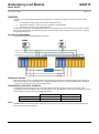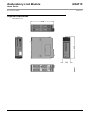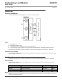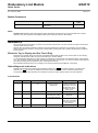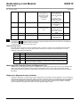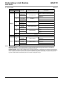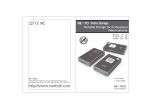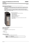
1
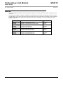
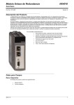
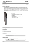
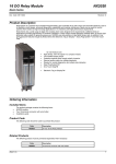
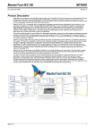
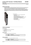
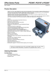
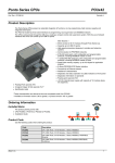
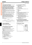
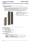
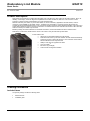
Redundancy Link Module NX4010 Nexto Series Doc. Code: CE114900 Revision: B Product Description Nexto Series is a powerful and complete Programmable Logic Controller (PLC) with unique and innovative features. Due to its flexibility, smart design, enhanced diagnostics capabilities and modular architecture, Nexto PLC can be used for control systems in medium and high-end applications or in high speed machinery NX4010 redundancy link module, a part of Nexto Series, is used to redundancy applications with half-clusters, where is necessary a high availability of automation system. The NX4010 is responsible for connecting the two half-clusters and providing the synchronism between them in such way that the standby half-cluster keeps all internal variables, input values and output values updated according to the active half-cluster. The interface between two redundant half-clusters is also redundant, where is formed by two cables of synchronism. Besides providing an interface between two redundant half-clusters, the module NX4010 also has an interface to the Redundancy Control Panel, PX2612 that is used to control and to verify the redundant system states. Its main features are: Allows full synchronization between two half-clusters Redundant channels of synchronism between the half-clustersAutomatically switchover (change of active half-cluster) in case of timeout communication between NX4010 and its respective CPU Ablility to shut down the opposite half-cluster One Touch Diag TM Electronic Tag on Display LCD and LED for diagnostic indication Ordering Information Included Items The product package contains the following items: Altus S. A. NX4010 module Installation guide 1 Redundancy Link Module NX4010 Nexto Series Doc. Code: CE114900 Revision: B Product Code The following code should be used to purchase the product: Code Description NX4010 Redundancy Link Module Related Products The following products must be purchased separately when necessary: Code Description PX2612 Redundancy Control Panel AL-2317/A CMDB9-CFDB9 Cable AL-2318/B CMDB9-CFDB9 Cable AL-2319 RJ45-RJ45 Cable Notes PX2612: a PX2612 is a control panel used to control and to verify the redundant system states. AL-2317/A, AL-2317/B: the cables AL-2317/A and AL-2317/B are used to connect the CONTROL interfaces of the both NX4010 at the PX2612 control panel. AL-2319: the cable AL-2319 is used to connect NET1 and NET2 interfaces of the NX4010 of the two redundant half-clusters. Innovative Features Nexto Series brings to the user several innovations in utilization, supervision and system maintenance. These features were developed focusing a new experience in industrial automation. The list below shows some new features that users will find in the NX4010 module: One Touch Diag TM: One Touch Diag is an exclusive feature that Nexto Series brings to PLCs. With this new concept, the user can check diagnostic information of any module present in the system directly on CPU’s graphic display with one single press in the diagnostic switch of the respective module. OTD is a powerful diagnostic tool that can be used offline (without supervisor or programmer), reducing maintenance and commissioning times. ETD – Electronic Tag on Display: Another exclusive feature that Nexto Series brings to PLCs is the Electronic Tag on Display. This new functionality brings the process of checking the tag names of any I/O pin or module used in the system directly to the CPU’s graphic display. Along with this information, the user can check the description, as well. This feature is extremely useful during maintenance and troubleshooting procedures. DHW – Double Hardware Width TM: Nexto Series modules were designed to save space in user cabinets or machines. For this reason, Nexto Series delivers two different module widths: Double Width (two backplane rack slots are required) and Single Width (only one backplane rack slot is required). This concept allows the use of compact I/O modules with a high-density of I/O points along with complex modules, like CPUs, fieldbus masters and power supply modules. iF Product Design Award 2012: Nexto Series was the winner of iF Product Design Award 2012 in industry + skilled trades group. This award is recognized internationally as a seal of quality and excellence, considered the Oscars of the design in Europe. Altus S. A. 2 Redundancy Link Module NX4010 Nexto Series Doc. Code: CE114900 Revision: B Product Features General Features NX4010 Backplane rack occupation 2 sequential slots Hot swap support Yes Status and diagnostic indication Display, web pages and CPU’s internal memory One Touch Diag (OTD) Yes Electronic Tag on Display (ETD) Yes Isolation NET 1 to logic NET 1 to protective earth NET 1 to NET 2 NET 2 to logic NET 2 to protective earth Logic to protective earth 1500 Vac / 1 minute 1500 Vac / 1 minute 1500 Vac / 1 minute 1500 Vac / 1 minute 1500 Vac / 1 minute 1500 Vac / 1 minute Current consumption from backplane rack power supply 500 mA Power dissipation 2.5 W IP level IP 20 Operating temperature 0 to 60 °C Storage temperature -25 to 75 °C Relative humidity for operation and storage 5 to 96 %, non condensing Conformal coating Yes Standards IEC 61131-2 CE, Electromagnetic Compatibility (EMC) and Low-Voltage Directive (LVD) Module dimensions (W x H x D) 36.00 x 114.63 x 115.30 mm Package dimensions (W x H x D) 44.00 x 122.00 x 147.00 mm Net weight 250 g Gross weight 300 g Notes Status and diagnostic indication: More information about diagnostic and status indication can be found on the topic Maintenance. Logic: Logic is the name for the internal interfaces such as processors, memories and backplane rack interfaces. Isolation: The CONTROL interface is located in the isolation group of Logic. It means that there isn’t isolation between Logic and CONTROL. Conformal coating: Conformal coating protects the electronic components inside the product from moisture, dust and other harsh elements to electronic circuits. NET 1 and NET 2 NET 1 and NET 2 are the external interfaces, called Redundancy Links. The Redundancy Links connect two NX4010, placed in different half-clusters and allow redundant data exchange between them. NET 1 and NET 2 form a redundant interface, it means that the system works properly with only one Redundancy Link, NET 1 or NET 2. In case of loss of link in one redundancy interface, the system will keep working and will indicate a diagnostic informing the loss of link. NET 1 interface must be connected to another NET 1 interface, while NET 2 interface must be connected to another NET 2 interface. Altus S. A. 3 Redundancy Link Module NX4010 Nexto Series Doc. Code: CE114900 Revision: B CONTROL CONTROL is the interface between NX4010 and the Redundancy Control Panel PX2612. This interface is used for three reasons: Control PX2612’s LEDs used to show the status of each half-cluster Read PX2612’s buttons to check if the user is requesting a manual operation Control the power supply of the opposite half-cluster Controlling the power supply of the opposite half-cluster is a very important point, because there are some extreme conditions, like loss of two Redundancy Links, where the only way to ensure that there is only one master for all remote I/Os is switching the opposite half-cluster off. System Configurations Suggested configurations using NX4010 are shown below: CP B CP A AL-2317/A AL-2317/B AL-2319 AL-2319 Software Features Nexto Series brings to the user the MasterTool IEC XE, a powerful tool that provides a complete interface used to program all Nexto Series’ Modules. This means that there is no additional software to make the redundancy parameterization, all settings are done in the same software used to program Nexto CPUs. Compatibility with Other Products The NX4010 module was developed to be used in Nexto Series half-clusters redundancy solution. Nexto Series’ CPUs documentation must be consulted to check which CPUs allows its use. The table below shows from which software version and product revision the listed modules are compatible with NX4010. Software/firmware version Product revision MT8500 1.20 or higher AC or higher NX3030 1.1.0.0 or higher AB or higher Notes Product review: if the software/firmware is upgraded in the field, the product reviewing indicated on the label will no longer match the actual review of the product. Altus S. A. 4 Redundancy Link Module NX4010 Nexto Series Doc. Code: CE114900 Revision: B Physical Dimensions Dimensions in mm. Altus S. A. 5 Redundancy Link Module NX4010 Nexto Series Doc. Code: CE114900 Revision: B Installation Electrical Installation The electrical installation on the backplane rack can be seen in the figure below. Notes 1234- Redundancy link. Redundancy interface control. The module is grounded through the Nexto Series backplane racks. The module power supply is derived from the connection to the backplane rack, not requiring external connections. All indication about half-cluster redundancy installation can be found at Nexto Series CPUs User Manual – MU214605. Mechanical Assembly The mechanical mounting of this module is described at Nexto Series User Manual – MU214600. There is no particular issue on the installation of this module. Configuration All indication about half-cluster redundancy configuration can be found at Nexto Series CPUs User Manual – MU214605. Process Data The process data, when available, are the variables used to access and control the module. The table below shows all the variables used by NX4010. Process data Description Type Update Reserved Reserved for internal use %QB (Read/ Write) Always Reserved Reserved for internal use %IB (Read) Always Reserved Reserved for internal use %IB (Read) Always Reserved Reserved for internal use %IW (Read) Always Notes Update: This field indicates if the respective process data is updated by CPU and NX4010. If it is set as Always, it means that the process data is always updated. Altus S. A. 6 Redundancy Link Module NX4010 Nexto Series Doc. Code: CE114900 Revision: B Module Parameters Name Description Standard value %Q Start Address of Module Diagnostics Defines the start address of the module diagnostics. - Notes Standard value: MasterTool IEC XE programmer fills it automatically, but allows the user to edit its initial offset. The limit depends on the CPU supported model (details at Nexto Series CPUs User Manual – MU214605). Maintenance Altus recommends that all modules’ connections be checked and that all dust or any kind of dirt at the module’s enclosure be removed at least every 6 months. NX4010 offers five important features to assist the user during maintenance: Electronic Tag on Display, One Touch Diag, Status and diagnostics indicators, web page with complete status and diagnostics list and status and diagnostics mapped to internal memory. Electronic Tag on Display and One Touch Diag Electronic Tag on Display and One Touch Diag are important features that provides for the user the option to check the tag, description and diagnostics related to a given module directly on the CPU display. To check the tag and diagnostics of a given module, it’s required only one short press on its diagnostic switch. After pressing once, CPU will start to scroll tag information and diagnostic information of the module. To access the respective description for the module, just long press the diagnostic switch of the respective module. More information about Electronic Tag on Display can be found at Nexto Series User Manual – MU214600. Status/Diagnostic Indications All Nexto slave modules have a display with the following symbols: D, E, 0, 1 and numeral characters. The states of the symbols D, E, 0, 1 are common for all Nexto series slave modules, these states can be consulted in the table below. The meaning of the numeral characters can be different for specific modules. NX4010 doesn’t use these segments. D and E States D E Description Causes Solution Priority Off Off Display fail or module off Disconnected module. No external supply or hardware fail Check if the module is completely connected to the backplane rack and if the backplane rack is supplied by an external power supply - On Off Normal use - - 9 (Lower) Blinking 1x Off Active Diagnostics There is at least one active diagnostic related to the module NX4010 Check the active diagnostic. 8 Blinking 2x Off CPU in STOP mode CPU in STOP mode Check if CPU is in RUN mode. More information can be found on CPU’s documentation. 7 Blinking 3x Off Reserved - Altus S. A. 6 7 Redundancy Link Module NX4010 Nexto Series Doc. Code: CE114900 Revision: B Blinking 4x Off Non fatal fault Failure in some hardware or software component, which does not have impact on the basic functionality of the product Check the module diagnostic information. If it is a hardware fault, provide the replacement of this part. If it is a software fault, please contact the Technical Support 5 Off Blinking 1x Parameterization error - Check if the module parameterization is correct. 4 Off Blinking 2x Loss of master Loss of communication between module and CPU Check if the module is completely connected to the backplane rack 3 Check if CPU is in RUN mode. Off Blinking 3x Reserved - - 2 Off Blinking 4x Fatal hardware error Hardware failure Contact Altus support team in case of fatal hardware error 1 (Higher) 0, 1 and Numeral Characters The segments 0 and 1 should be normally off. These two segments will start to blink when the module is on the Diagnostic Mode (Electronic Tag on Display and One Touch Diag). The Numeral Characters aren’t used in this module. RJ45 Connector LEDs Both LEDs placed in the RJ45 connectors, identified by NET 1 and NET 2, help the user in the installed physical network problem detection, indicating the network LINK speed and the existence of interface communication traffic. The LEDs description is presented in the table below. Yellow Green Off Off Network LINK absent. Description On Off 10Mbits/s network LINK. On On 100Mbits/s network LINK. Blinking – Occurrence of transmission or reception. It blinks when there is module demand and not every transmission or reception, i.e. blinking frequency doesn’t correspond to data transmission or reception frequency. Web Page with Complete Status and Diagnostic List Another way to access diagnostic information on Nexto Series is via web pages. Nexto Series CPUs have an embedded web pages server that provides all Nexto status and diagnostic information, which can be accessed using a simple browser. More information about web page with complete status and diagnostic list can be found at Nexto Series CPUs User Manual – MU214605. Diagnostics Mapped through Variables All NX4010’s diagnostics can be accessed through variables that can be handled by the user application or even forwarded to a supervisory system using a communication channel. There are two different ways to access diagnostics in the user application: using symbolic variables with AT directive or addressing memory. Altus recommends use symbolic variables for diagnostic accessing. The table below shows all available diagnostics for NX4010 and their respective memory address, description, symbolic variable and string that will be shown on the CPU graphical display and web Altus S. A. 8 Redundancy Link Module NX4010 Nexto Series Doc. Code: CE114900 Revision: B Addressing Memory Variable Bit %QB(n) 0..7 0 Diagnostic Message Symbolic Variable DG_NX4010.tDgGeneral. Reserved MODULE W/ DIAGNOSTICS TRUE – Module has active diagnostics bActiveDiagnostics - 1 MODULE W/ FATAL ERROR %QB(n+1) CONFIG. MISMATCH FALSE – No fatal error TRUE – Parameterization error bParameterizationError FALSE – Parameterization ok - 3 WATCHDOG ERROR TRUE – Watchdog has been detected bWatchdogExpiredError FALSE – No watchdog - 4 OTD SWITCH ERROR bFailureontheKey - %QB(n+2) 5..7 Reserved 0..7 Reserved 0 NET1 LINK DOWN FALSE – Module doesn’t have active diagnostic TRUE – Fatal error bFatalError 2 Description bNET1LinkDown TRUE – Failure on the diagnostic switch FALSE – No failure on the diagnostic switch TRUE – NET1 interface isn’t properly connected FALSE – NET1 interface is connected %QB(n+3) 1 NET2 LINK DOWN bNET2LinkDown TRUE – NET2 interface isn’t properly connected FALSE – NET2 interface is connected 2..7 Reserved Notes Addressing Memory: “n” is the address defined in the field %Q Start Address of Diagnostic Module on the NX4010’s configuration screen – Modules Parameters tab in the MasterTool IEC XE. Symbolic Variable: Some symbolic variables serve to accessing diagnostics. This diagnostics are stored into the addressing memory, then the AT directive is used to map the symbolic variables in the addressing memory. The directive AT is a reserved word in the MasterTool IEC XE that uses this directive to declares the diagnostics automatically on a symbolic variables. All symbolic variables declared automatically can be found inside of Diagnostics object. Altus S. A. 9 Redundancy Link Module NX4010 Nexto Series Doc. Code: CE114900 Revision: B Manuals For correct application and utilization of Nexto Redundancy Systems, Nexto Series CPUs User Manual – MU214605 must be consulted. For further technical details, configuration, installation and programming of Nexto Series, the table below should be consulted. The table below is only a guide of some relevant documents that can be useful during the use, maintenance, and programming of NX4010. The complete and updated table containing all documents of Nexto Series can be found at Nexto Series User Manual – MU214600. Altus S. A. Document Code Description Language CE114000 CT114000 CS114000 Nexto Series – Technical Characteristics Série Nexto – Características Técnicas Serie Nexto – Especificaciones y Configuraciones English Portuguese Spanish MU214600 MU214000 MU214300 Nexto Series User Manual Manual de Usuário Série Nexto Manual del Usuario Serie Nexto English Portuguese Spanish MU214605 MU214100 MU214305 Nexto Series CPUs User Manual Manual de Usuário UCPs Série Nexto Manual del Usuario UCPs Serie Nexto English Portuguese Spanish MU299609 MU299048 MU299800 MasterTool IEC XE User Manual Manual de Usuário MasterTool IEC XE Manual del Usuario MasterTool IEC XE English Portuguese Spanish 10