1
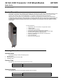
24 Vdc 8 DO Transistor / 8 DI Mixed Module NX1005 Nexto Series Doc. Code: CE114300 Revision: D Product Description Nexto Series is a powerful and complete Programmable Logic Controller (PLC) with unique and innovative features. Due to its flexibility, smart design, enhanced diagnostics capabilities and modular architecture, Nexto can be used for control systems from medium to high-end large applications or in machinery with high performance requirements. Nexto Series has a wide range of I/O modules that were designed to fit requirements in different kinds of applications providing high-density points per module. NX1005 is a mixed I/O module that delivers 8 protected source type outputs and 8 isolated sink/source type inputs for general purpose use. NX1005 uses only one slot of Nexto Series Backplane Rack and has exclusive features brought by Nexto Series such as Electronic Tag on DisplayTM, Easy Plug SystemTM and One Touch DiagTM. Its main features are: High density, with 16 I/O points in a single width module Isolated outputs Isolated inputs in two groups Short-circuit protection and diagnostic for outputs Protection against polarity inversion for external power supply External power supply low voltage diagnostic Display for output/input state indication and diagnostics Easy Plug SystemTM One Touch DiagTM Electronic Tag on DisplayTM Ordering Information Included Items The product package contains the following items: NX1005 module 20-terminals connector with wire holder Installation guide Product Code The following code should be used to purchase the product: Code NX1005 Description 24 Vdc 8 DO Transistor / 8 DI Mixed Module Related Products The following product must be purchased separately when necessary: Code NX9403 Altus S. A. Description 20-terminal connector with cable guide 1 24 Vdc 8 DO Transistor / 8 DI Mixed Module NX1005 Nexto Series Doc. Code: CE114300 Revision: D Innovative Features Nexto Series brings to the user several innovations in utilization, supervision and system maintenance. These features were developed focusing a new experience in industrial automation. The list below shows some new features that users will find in the NX1005 module: Easy Plug System TM: Nexto Series has an exclusive method to plug and unplug I/O connectors. The entire connector can be easily removed with a single movement and with no special tools or huge effort. In order to plug the connector back to the module, close the front cover and the connector will be fit, ready to use. One Touch Diag TM: One Touch Diag is an exclusive feature that Nexto Series brings to PLCs. With this new concept, the user can check diagnostic information of any module present in the system directly on CPU’s graphic display with one single press in the diagnostic switch of the respective module. OTD is a powerful diagnostic tool that can be used offline (without supervisor or programmer), reducing maintenance and commissioning times. ETD – Electronic Tag on Display: Another exclusive feature that Nexto Series brings to PLCs is the Electronic Tag on Display. This new functionality brings the process of checking the tag names of any I/O terminal or module used in the system directly to the CPU’s graphic display. Along with this information, the user can check the description, as well. This feature is extremely useful during maintenance and troubleshooting procedures. IF Product Design Award 2012: Nexto Series was the winner of iF Product Design Award 2012 in industry + skilled trades group. This award is recognized internationally as a seal of quality and excellence, considered the Oscars of the design in Europe. Altus S. A. 2 24 Vdc 8 DO Transistor / 8 DI Mixed Module NX1005 Nexto Series Doc. Code: CE114300 Revision: D Product Features General Features NX1005 Backplane rack occupation 1 slot One Touch Diag (OTD) Yes Electronic Tag on Display (ETD) Yes Status and diagnostic indication Display, web pages and CPU’s internal memory Hot swap capability Yes Isolation Outputs to inputs Outputs to logic Outputs to protective earth Inputs group to inputs group Inputs to logic Inputs to outputs power supply Inputs to protective earth Logic to protective earth 1000 Vac / 1 minute 500 Vac / 1 minute 1250 Vac / 1 minute 1000 Vac / 1 minute 2500 Vac / 1 minute 1000 Vac / 1 minute 2500 Vac / 1 minute 1250 Vac / 1 minute Current consumption from rack PSU 160 mA Maximum power dissipation 4W IP level IP 20 Operating temperature 0 to 60 °C Storage temperature -25 to 75°C Operating and storage relative humidity 5 to 96 %, non-condensing Conformal coating Yes IEC 61131-2 CE, Electromagnetic Compatibility (EMC) and LowVoltage Directive (LVD) Standards Module dimensions (W x H x D) 18.00 x 114.62 x 117.46 mm Package dimensions (W x H x D) 25.00 x 122.00 x 147.00 mm Weight 200 g Weight with package 250 g Notes Conformal coating: Conformal coating protects the electronic components inside the product from moisture, dust and other harsh elements to electronic circuits. Altus S. A. 3 24 Vdc 8 DO Transistor / 8 DI Mixed Module NX1005 Nexto Series Doc. Code: CE114300 Revision: D Transistor Digital Output NX1005 Output type Transistor isolated source type output Number of outputs 8 Maximum output current 1 A @ 30 Vdc per output 4 A @ 30 Vdc in group Leakage current 30 µA On state resistance 0.25 Ω External power supply 19.2 to 30 Vdc Switching time 100 us - off-to-on transition 400 us - on-to-off transition Maximum switching frequency 500 Hz Output update time 2 ms Configurable parameters Yes, output behavior with CPU in STOP mode Output state indication Yes Output protections Yes, power supply polarity inversion protection, protection against surge voltages and short circuit protection Notes Maximum output current: When required, use a higher current value. It’s possible to use more than one output connected on the same load. In this case the maximum current is the sum of individual currents where up to 4 outputs can be used together. For example: It’s possible to drive a given load with 1.5 A using 2 outputs. All outputs used on a given load must be enabled/ disabled at the same time. Power supply: The terminals 19 and 20 are used to supply voltage only to the outputs. NX1005 is supplied by the Power Supply Module placed on the Nexto Backplane Rack. Switching time: The required time to turn off one specific output depends on the load. A lower resistance load results in a shorter time to disable the output. The given time refers to the maximum time to disable an output connected to a 12.5 kΩ resistive load, which is the maximum allowable resistance defined by IEC 61131 for digital input modules. Digital Input NX1005 Input type Sink or source type 1 Number of inputs 8 Input voltage 24 Vdc 15 to 30 Vdc for level logic 1 0 to 5 Vdc for level logic 0 Input impedance 4.18 kΩ - input 00 4.90 kΩ - inputs 01 to 07 Maximum input current 6 mA for 24 Vdc – input 00 5 mA for 24 Vdc – input 01 to 07 Input state indication Yes Input update time 2 ms Input filter 100 µs – by hardware 2 ms to 255 ms – by software Notes Input type: NX1005’s inputs are divided in two input groups: 00 to 03 and 04 to 07. Each group can be used as source inputs as well as sink inputs independently of the type used in the other group. To use an input group as source inputs, the respective common terminal must be connected to 24 Vdc. To use an input group as sink inputs, the respective common terminal must be connected to 0 Vdc. For more information please check the section Installation in this document. Altus S. A. 4 24 Vdc 8 DO Transistor / 8 DI Mixed Module NX1005 Nexto Series Doc. Code: CE114300 Revision: D Installation Electrical Installation The figure below shows an example where each NX1005’s output is connected to the load and where the inputs 00 to 03 are being used as sink inputs and the inputs 04 to 07 are being used as source inputs. Diagram Notes 1 – Typical usage of sink digital inputs, C1 is the 0 Vdc common to input group I00 to I03. 2 – Typical usage of source digital inputs, C2 is the +24 Vdc common to input group I04 to I07. 3 – Typical usage of source digital outputs. 4 – External power supply to supply the outputs, V1 is connected to +24 Vdc and N1 is connected to 0 Vdc. 5 – The module is grounded through the Nexto Series backplane racks. 6 – The module power supply is derived from the connection to the backplane rack, not requiring external connections. Altus S. A. 5 24 Vdc 8 DO Transistor / 8 DI Mixed Module NX1005 Nexto Series Doc. Code: CE114300 Revision: D Connector Pinout The following table shows the description of each connector terminal. Terminal Number Description 1 Input 00 2 Input 01 3 Input 02 4 Input 03 5 Common for inputs 00 to 03 6 Input 04 7 Input 05 8 Input 06 9 Input 07 10 Common for inputs 04 to 07 11 Output 00 12 Output 01 13 Output 02 14 Output 03 15 Output 04 16 Output 05 17 Output 06 18 Output 07 19 (V1) + 24 Vdc for outputs 00 to 07 20 (N1) 0 Vdc for outputs 00 to 07 Suppressor Circuit For further information about suppressor circuit, consult Nexto Series User Manual - MU214600. ATTENTION: Atmospheric discharges (thunders) may cause damages to the modules although it’s protections. Additional protections should be used if module’s power comes from a power supply located outside the cabinet where the module is installed, because it could be vulnerable to this kind of discharges. If the field wiring of the output points is susceptible to this kind of discharge, surge suppressors should be used. Mechanical and Electrical Assembly The mechanical and electrical mounting and the connector insertion and removing for a single width I/O modules are described at Nexto Series User Manual – MU214600. Compatibility with Other Products The following table provides information regarding the compatibility of the module NX1005 and Nexto Series programming tool MasterTool IEC XE. NX1005 Software Version Compatible Version Revision Feature MasterTool IEC XE 1.0.0.0 AA Mode 0 1.22 or higher 1.1.0.1 or higher AB or higher Mode 1, 2, 3, 4 1.29 or higher Hardware External Event 1.31 or higher Nexto CPU’s 1.0.0.9 or higher 1.2.2.1 or higher Notes Mode 1, 2, 3, 4: The pulse capture, counters and period measurement features are only available from the software versions indicated in the table. Altus S. A. 6 24 Vdc 8 DO Transistor / 8 DI Mixed Module NX1005 Nexto Series Doc. Code: CE114300 Revision: D Hardware external event: The hardware external event feature is available from the software versions indicated in the table. More information about Hardware External Event can be found at Nexto Series CPUs Utilization Manual – MU214605. Product review: if the software is upgraded in the field the product reviewing indicated on the label will no longer match the actual review of the product. Physical Dimensions Nexto Series User Manual - MU214600 should be consulted for general measurement of installation panel. Dimensions in mm. Altus S. A. 7 24 Vdc 8 DO Transistor / 8 DI Mixed Module NX1005 Nexto Series Doc. Code: CE114300 Revision: D Configuration NX1005 was developed to be used with Nexto Series products. All Nexto Series products configurable in MasterTool IEC XE. All configuration data of a given module can be accessed through a double click in the desired module on the Graphical Editor. Process Data or I/O Mapping in PRFIBUS-DP Network Process Data, when available, are the variables that are used to access and control the module. The list below describes all variables delivered by NX1005. The process data of the module, when inserted in a PROFIBUS network, can be accessed through variables. The NX1005 module has a byte to access the input data and another byte to access the output data. The module NX1005 HSC is described in the table below that presents the variables organizational structure in the UCP memory. Besides this data, NX1005 also provides a set of variables containing information related to diagnostics which are also described in this document. Variable Size Process Data Description Type Update Output (Read/Write) Selectable %QB(n) BYTE Digital Outputs Byte-1 Output Value of channels 10 to 17 %QB(n+1) BYTE High Speed Counter Input 00 Command Input 00 counter command structure Output (Write) Selectable %QB(n+2) DWORD High Speed Counter Input 00 Preset Value Input 00 counter preset command Output ( Write) Selectable %QB(n+6) BYTE High Speed Counter Input 01 Command Input 01 counter command structure Output (Write) Selectable %QB(n+7) DWORD High Speed Counter Input 01 Preset Value Input 01 counter preset command Output (Write) Selectable %QB(n+11) BYTE Pulse-Catch Reset – Byte 0 Reset command to recognize the pulse capture from inputs 00 to 07 Output (Write) Selectable %IB(n) BYTE Digital Inputs Byte-0 Input value of channel 00-07 Input (Read) Always %IB(n+1) BYTE High Speed Counter Input 00 Status Input 00 counter command status Input (Read)) Selectable %IB(n+2) DWORD High Speed Counter Input 00 Current Value Input 00 counter value Input (Read) Selectable %IB(n+6) BYTE High Speed Counter Input 01 Status Input 01 counter command status Input (Read) Selectable %IB(n+7) DWORD High Speed Counter Input 01 Current Value Input 01 counter value Input (Read) Selectable %IB(n+11) DWORD Input 02 Period Value of the period measurement of the input 02 Input (Read) Selectable Notes Update: The field Update indicates if, by default, the respective process data is updated by CPU and NX1005. When defined as Always, it means that the process data is always updated. When defined as Selectable, means that the user can select if the respective process data will be updated or not. All these process data are exchanged between CPU and NX1005 through the bus, to improve CPU performance, it’s recommended to update only the process data that will be used in the application. Altus S. A. 8 24 Vdc 8 DO Transistor / 8 DI Mixed Module NX1005 Nexto Series Doc. Code: CE114300 Revision: D Module Parameters Name Description Standard value Operating Mode Set special features configuration mode Mode 0 Input Filter Enable Mask Enables or disables input filter feature, per channel False Input Filter Time Constant Sets input filter time constant (ms) 7 Pulse Catch Enable Mask Enables or disables pulse catch False Elongation Time of Pulse Catch Sets the Elongation Time of the pulse catch (ms) 50 Period Measurement Enable Mask Enables or disables period measurement (available only to input 02) False Output Behavior on CPU STOP Mode – Group 0 This parameter is individually defined for each output and defines the behavior of each output when CPU is in STOP mode False User Defined Output Value – Group 0 This parameter defines individually the logic level that each output should get when CPU is in STOP mode False %Q Start Address of Module Diagnostics Area Defines the start address of the module diagnostics - Notes Operating Mode: For further information, the Operating Modes section should be consulted. Input Filter Enable Mask: The field can be selected by the user to enable the input filter feature in a specific channel. If the input filter is enabled in a channel, the module will reject pulses smaller than the time configured in the Input Filter Time Constant. Input Filter Time Constant: The field determines the time to apply in the filter and this parameter can be set from 2 to 255 ms. If enabled some different operation mode than Mode 0, this parameter is ignored for inputs related to the selected operating mode, the remaining inputs must have the same behavior of Mode 0. Elongation Time of Pulse Catch: This field determines the time that the pulse detected by the input module will remain active, so it is suggested that the set value in this field is always greater than the cycle time of application. Output Behavior on CPU STOP Mode – Groups 0 and 1: This is the behavior of the outputs when the CPU is in STOP mode. During procedures of CPU exception, reset warm, reset cold, reset origin or power supply failure, this behavior may be in effect while CPU is changing through internal states. If module is hot-swapped with CPU in STOP mode, the output behavior will not be in effect. After downloading a project with different behavior settings, the new settings will only be updated only on CPU RUN state. Altus S. A. 9 24 Vdc 8 DO Transistor / 8 DI Mixed Module NX1005 Nexto Series Doc. Code: CE114300 Revision: D Operating Modes NX1005 provides five operation modes, where each one has some functionality features in common and also specific features. The table below describes the available features in each operation mode. Operating Mode Description Mode 0 Input 00 to 07: Standard digital input Mode 1 Input 00 to 07: Pulse catch Input 00 to 07: Standard digital input (only on pulse catch disabled inputs) Mode 2 Input 00: Counter 1, counting direction defined by software Input 01: Standard digital input Input 02: Period measurement Input 03 to 07: Standard digital input Mode 3 Input 00: Counter 1, counting direction defined by input 01 Input 01: counting direction control of Counter 1 Input 02: Period measurement Input 03 to 07: Standard digital input Mode 4 Input 00: Counter 1, counting direction defined by software Input 01: Counter 2, counting direction defined by software Input 02: Period measurement Input 03 to 07: Standard digital input Mode 1: Pulse Catch Pulse catch functionality can be configured when you select the operation mode 1, as can be seen in the table above. This feature is used to detect fast pulses, which can not be identified during a standard scan of the application, and increase them for such a scan can detect. The capture of the pulse can be enabled individually for each digital input via Pulse-Catch Enable Mask parameter. The inputs that are not used as pulse catch can be used as standard digital input. The behavior of the pulse catch is associated with the identification of pulses with not less than 1 ms width, generated by field signal in the respective input enabled. When this is identified, the module indicates through the Digital Inputs Byte-0 variables setting the bit corresponding to input that is with this feature enabled. This bit will remain on for the time configured in the Pulse-Catch Elongation Time parameter. We recommend configuring in this parameter a time greater than the Interval Time of the Main Task; otherwise the standard scan may not detect this. The command Pulse-Catch Reset has priority over the field signal, i.e., when this command is active for the corresponding input, the pulses generated by the field signal are ignored. In order to exemplify the behavior described above, the figures below indicate the State of the field signal, Pulse-Catch Reset command and the result of this functionality in Digital Inputs Byte-0 variables. Notes 1: Pulse generated by the field signal more than 1 ms at the input 00 but with the command Pulse-Catch Reset bit 0 on, in this case the user will not identify any change in the Digital Inputs Byte-0 bit 0 variable. 2: Pulse generated by field signal more than 1 ms at the input 00 with Pulse-Catch Reset bit 0 command off; in this case the module sets the bit 0 of the Digital Inputs Byte-0 variable, keeping it in TRUE until the reset command. In this case the application scan interval identifies the pulse that was captured by this feature. 3: Displays the reset signal turning off the bit 0 of the Digital Inputs Byte-0 variable. Altus S. A. 10 24 Vdc 8 DO Transistor / 8 DI Mixed Module NX1005 Nexto Series Doc. Code: CE114300 Revision: D 4: This case presents a pulse equal to 1 ms in field signal, which is identified by the module. In this way the bit 0 of the Digital Inputs Byte-0 variable remains on until the reset command. Notes 1 and 2: If the field signal does not generate pulses and stay always on, the signal from the Digital Inputs Byte-0 variable will be switched on whenever there is a transition from the reset command. In this situation, the signal of Digital Inputs Byte-0 variable may only be turned on when the Pulse-Catch Reset command is off. Mode 2: Counter The counter in operation mode 2 is able to register Input 00 count and set the count direction by up and down functions via software command, which is available in bit 0 of the High Speed Counter Input 00 Command, called Direction. The count value can be read through the variable High Speed Counter Input 00 Current Value which can assume the values defined in the count presented on the table of characteristics of the mode 2. To stop counting, use the Stop Counter command available in the command variable. Other commands like Preset, Reset and Hold counter can also be performed. The logical state of activation of any command is logic level 1, and these will be accepted only if the counter is running or stopped (STOP). To run a stop counting, using the command Stop Counter in the variable command. Other commands such as Preset, Reset and Hold counter can also be performed. The logical state of any command activation is logic level 1, and these will be accepted only if the meter is running or stopped mode (STOP). If the Reset and Preset commands are sent simultaneously to the module, the Reset command is performed. The same applies to the Stop and Hold commands, but in this case the Stop command is performed. The status bit Direction, Run and Stop modes according to the direction of the count. However, in Hold, it indicates the last known good configuration. The status bit “Direction” – in Run and Stop modes - informs the counting direction. But in Hold mode, it indicates the last valid configuration. The Reset and Preset status indicate when the command was successfully held. Their value resets when command bit goes to zero. In case of counter overflow, that is, when the value of the count reaches its maximum value the count will automatically assume the minimum value. Counter Mode 2 Count input Input 00 Count range -2.147.483.648 to +2.147.483.647 Count direction control By software Maximum frequency of the count input (fc) 20 kHz Minimum time of count direction setting 10 ms Update time 2 ms Count input detection edge Rise, active on logical level 1 ATTENTION: It is recommended to use a duty-cycle of 50% for counter inputs. Altus S. A. 11 24 Vdc 8 DO Transistor / 8 DI Mixed Module NX1005 Nexto Series Doc. Code: CE114300 Revision: D Process Data High Speed Counter Input 00 Command High Speed Counter Input 00 Preset Value High Speed Counter Input 00 Status High Speed Counter Input 00 Current Value Bit Command Description 0 Direction 1 Stop Counter Runs the counter stop FALSE – running counter TRUE – stops the count 2 Hold Counter Freezes the count value FALSE – running counter TRUE – freezes value in the variable HSC Input 00 Current Value, but continues to count 3 Reset Counter TRUE – returns the count to zero 4 Preset Counter TRUE – loads the counter with the value of HSC Input Preset Value Sets the direction of the count: FALSE – count up TRUE – countdown 5 to 7 Reserved DINT Contains the value to be loaded into the counter 0 Direction 1 Stop Counter Indicates whether the counter is stopped 2 Hold Counter Indicates whether the value of the counter was frozen 3 Reset Counter Indicates that the count returned to zero 4 Preset Counter Indicates that the value of HSC Input Preset Value was loaded into the counter. Indicates the direction of the count 5 to 7 Reserved DINT Contains the value of the count Mode 3: Counter The count mode available in operating mode 3 has the same functionality of the mode 2 with some particularities: the count direction is not configured by software but rather through the logical state of the input 01. The option “count up” is defined by the logical state 0 and countdown by logical state 1. The other commands have the same operating form of mode 2. The table below presents the general characteristics and limits in this mode. Counter Mode 3 Altus S. A. Count input Input 00 Control input Input 01 Count range -2.147.483.648 to +2.147.483.647 Maximum frequency of the count input (fc) 20 kHz Maximum frequency of the control input 2 kHz Minimum time control input configuration 100 us Update time 2 ms Count input detection edge Rise, active on logical level 1 Control input detection edge Rise – countdown Fall – count up 12 24 Vdc 8 DO Transistor / 8 DI Mixed Module NX1005 Nexto Series Doc. Code: CE114300 Revision: D The chart below shows the behavior of the counter input 00 in relation to input 01 which serves to set the count direction. Notes fc: sets the maximum frequency of the count signal. td: sets the minimum time for count signal identification, and the minimum value is 100 us. Mode 4: Counter The count mode available in operating mode 4 has two counters: fast count input (Input 00 counter) and count input (Input 01 counter). The commands operate in the same manner as in mode 2, whose count direction is determined by software. The table below presents the general characteristics and limits in this mode. Counter Mode 4 Fast count input Input 00 Count input Input 01 Count range -2.147.483.648 to +2.147.483.647 Maximum frequency of the fast count input 20 kHz Maximum frequency of the count input 2 kHz Minimum time count direction configuration 10 ms Update time 2 ms Fast count input detection edge Rise, active on logical level 1 Count input detection edge Rise, active on logical level 1 Note Update time: Is the time required to update a new measurement. Altus S. A. 13 24 Vdc 8 DO Transistor / 8 DI Mixed Module NX1005 Nexto Series Doc. Code: CE114300 Revision: D Period Measurement in Modes 2, 3 and 4 The period measurement mode is available in operating modes 2, 3 and 4, at the input 02. General information and limits are presented in the table below. Period Measurement Measurement input Input 02 Minimum period / Maximum frequency 200 us / 5 kHz Maximum period / Minimum frequency 1 s / 1 Hz Sensitivity 1 us Precision < 2% of the measured value Pulses for measuring 4 pulses Update time 2 ms Detection edge Rise, active on logical level 1 Notes Pulses for measuring: For period measuring are necessary only four pulses on rise edge of the signal. Update time: Is the time required to update a new measurement. ATTENTION If there is no input signal, Input 02 Period will show the last valid value for 2s and after will show zero, if there is a signal with frequency out of range specified above, the value shown in Input 02 Period is zero. Module Usage. General Purpose Input Read NX1005 has one variable to access its inputs (Digital Inputs Byte-0). This variable has eight bits where each bit represents the physical state of each input channel. The relation between each bit and its respective input can be found on the Bus I/O Mapping tab General Purpose Output Write NX1005 has one variable to control its outputs (Digital Outputs Byte-1). This variable has eight bits where each bit represents the output state of a given output channel. The relationship between each bit and its respective output can be found on the Bus I/O Mapping tab. Maintenance Altus recommends that all modules’ connections should be checked and any dust or any kind of dirt located in the module’s enclosure should be removed at least every 6 months. NX1005 offers five important features to assist users during the maintenance: Electronic Tag on Display, One Touch Diag, Status and Diagnostics Indicators, Web Page with Complete Status and Diagnostics List and Diagnostics Mapped to Variables, Electronic Tag on Display and One Touch Diag. Electronic Tag on Display and One Touch Diag are important features that provide to the user the option to check the tag, description and diagnostics related to a given module directly on the CPU display. To check the tag and diagnostics of a given module, it’s required only one short press on its diagnostic switch. After pressing once, CPU will start to scroll tag information and diagnostics information of the module. To access the respective module description just long presses (longer than 1 s) the diagnostic switch of the respective module. More information about Electronic Tag on Display can be found at Nexto Series CPUs Utilization Manual – MU214605. Status and Diagnostics Indicators Nexto I/O modules have a display with the following symbols: D, E, 0, 1 and numerical characters. The states of the symbols D, E, 0, 1 are common for all Nexto Series modules. These states can be consulted in the table below. The meaning of the numerical characters can be different for specific modules. In case of digital output, the numerical characters show the respective logic output state. When the numerical character is on, the respective output is also on, and Altus S. A. 14 24 Vdc 8 DO Transistor / 8 DI Mixed Module NX1005 Nexto Series Doc. Code: CE114300 Revision: D if the numerical character is off, the respective output is also off. In case of digital inputs, the numerical characters show the respective logic input state. When the numerical character is on, the respective input is also on, and if the numerical character is off, the respective input is also off. The relationship between the input/output number and its respective numerical character can be found on the following figure. D and E States D Description Causes Solution Priority Check if the module is completely connected to the backplane rack and if the backplane rack is supplied by an external power supply - Off Off Display fail or module off - On Off Normal use - 9 (Lower) There is at least one active diagnostic related to the module NX1005 Check what the active diagnostic is. More information can be found at Diagnostics Mapped to Variables section of this document 8 Check if CPU is in RUN mode or if PROFIBUS Master is in OPERATE mode. More information can be found on CPU’s or PROFIBUS Master’s documentation 7 Off Active Diagnostic Blinking 2x Off CPU in STOP mode. If the module is in a Remote PROFIBUS, Master is in Clear state. - Blinking 3x Off Reserved - - 6 Check the module diagnostic information. If it is a hardware fault, provide the replacement of this part. If it is a software fault, please contact the Technical Support 5 Blinking 1x Blinking 4x Off Non Fatal Fault Failure in some hardware or software component, which does not have impact on the basic functionality of the product Off Blinking 1x Parameterizatio n error NX1005 isn’t parameterized or didn’t receive the new parameterization - 4 Loss of master Loss of communication between module and CPU or module and PROFIBUS head. Check if the module is completely connected to the backplane rack Check if CPU is in RUN mode or if PROFIBUS head is Active. 3 Off Blinking 2x Off Blinking 3x Reserved - - 2 Blinking 4x Fatal hardware fault - - 1 (Higher) Off Altus S. A. E 15 24 Vdc 8 DO Transistor / 8 DI Mixed Module NX1005 Nexto Series Doc. Code: CE114300 Revision: D 0, 1 and Numerical Characters The segments 0 and 1 are used to group the numerical characters used for the 8 inputs and the numerical characters used for the 8 outputs. The numerical characters that are placed at the right side of character 0 represent the inputs from 00 to 07, where character 0 is related to input 00 and character 7 is related to input 07. In the same way, the numerical characters that are placed at the right side of character 1 represent the outputs from 10 to 17, where character 0 is related to output 10 and character 7 is related to output 17. The figure below shows the relationship between numerical characters and the respective inputs/ outputs. Web Page with Complete Status and Diagnostics List Another way to access diagnostics information on Nexto Series is via web pages. Nexto Series CPUs have an embedded web page server that provides all Nexto status and diagnostic information that can be accessed using a browser. More information about web page with complete status and diagnostic List can be found at Nexto Series CPUs User Manual – MU214605. Diagnostics Mapped to Variables All NX1005’s diagnostics can be accessed through variables that can be handled by the user application or even forwarded to a supervisory system using a communication channel. There are two different ways to access diagnostics in the user application: using symbolic variables with AT directive or direct representation variable. Altus recommends the use of symbolic variables. The table below shows all available diagnostics for NX1005 and their respective memory addresses, description, symbolic variable and string that will be shown on the CPU graphical display and web. Altus S. A. 16 24 Vdc 8 DO Transistor / 8 DI Mixed Module NX1005 Nexto Series Doc. Code: CE114300 Revision: D General Diagnostics Direct Representation Variable Variable Bit %QB(n) 0..7 0 Diagnostic Message Symbolic Variable DG_modulename.tGeneral. bActiveDiagnostics MODULE W/ FATAL ERROR bFatalError TRUE – Module has active diagnostics FALSE – Module doesn’t have active diagnostic TRUE – Fatal error CONFIG. MISMATCH bConfigMismatch TRUE – Parameterization error - - FALSE – Parameterization ok 2 WATCHDOG ERROR 3 bWatchdogError TRUE – Watchdog has been detected - FALSE – No watchdog OTD SWITCH ERROR TRUE – Module has switch failure 4 bOTDSwitchError - 5..7 - 25 FALSE – No fatal error - %QB(n+1 PROFIBUS Message Code Reserved MODULE W/ DIAGNOSTICS NO DIAG 1 Description FALSE – Diagnostics switch ok 26 27 28 Reserved Detailed Diagnostics Direct Representation Variable Variable Diagnostic Message Symbolic Variable DG_modulename.tDetailed. Bit Output short circuit %QB(n+2) 0 bOutputShortCircuit - 1..7 0 bNoExternalSupply - 1..7 TRUE – Short circuit at outputs 10 to 17 FALSE – No short circuit at outputs 10 to 17 PROFIBUS Message Code 16 Reserved NO EXTERNAL SUPPLY %QB(n+3) Description TRUE – No external supply at outputs 10 to 17 FALSE – External supply ok at outputs10 to 17 24 Reserved Notes Direct Representation Variable: “n” is the address defined in the field %Q Start Address of Diagnostic Area on the NX1005’s configuration screen – Modules Parameters tab in the MasterTool IEC XE. Symbolic Variable: Some symbolic variables serve to access diagnostics. These diagnostics are stored in the direct representation variable, so the AT directive is used to map the symbolic variables in the direct representation variable. The directive AT is a reserved word in the MasterTool IEC XE, that uses this directive to declare the diagnostics automatically on symbolic variables. All symbolic variables declared automatically can be found inside of the Diagnostics object Altus S. A. 17 24 Vdc 8 DO Transistor / 8 DI Mixed Module NX1005 Nexto Series Doc. Code: CE114300 Revision: D Hot Swap This product supports hot swap. For further information about how to correctly perform a hot swap, consult Nexto Series User Manual - MU214600. Manuals For further technical details, configuration, installation and programming of Nexto Series the table below should be consulted. The table below is only a guide of some relevant documents that can be useful during the use, maintenance, and programming of NX1005. The complete and updated table containing all documents of Nexto Series can be found at Nexto Series User Manual – MU214600. Altus S. A. Document Code Description Language CE114000 CT114000 CS114000 Nexto Series – Features and Configuration Série Nexto – Características e Configurações Serie Nexto – Especificaciones y Configuraciones English Portuguese Spanish MU214600 MU214000 MU214300 Nexto Series User Manual Manual de Usuário Série Nexto Manual Del Usuario Serie Nexto English Portuguese Spanish MU214605 MU214100 MU214305 Nexto Series CPUs User Manual Manual de Utilização UCPs Série Nexto Manual del Usuario UCPs Serie Nexto English Portuguese Spanish MU299609 MU299048 MU299800 MasterTool IEC XE User Manual Manual de Usuário MasterTool IEC XE Manual Del Usuário MasterTool IEC XE English Portuguese Spanish 18