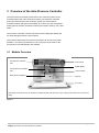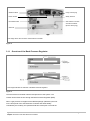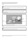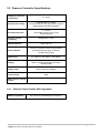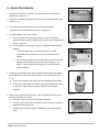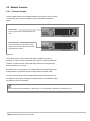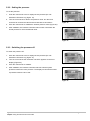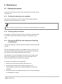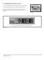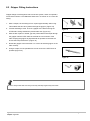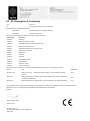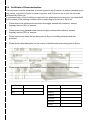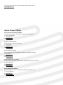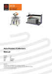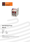
1
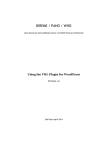
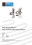
Asia Pressure Controller Manual Syrris Ltd Version: 1.2 Author: MD Date: 07/10/2015 P/N: 2000253 Disclosure This document is confidential and is the property of Syrris Ltd. No attempt should be made to copy this document in any way without prior consent. © 2012 Syrris Ltd all rights reserved [Page left blank] Syrris Ltd: Asia Pressure Controller - Manual Chapter: Introduction Page 2 of 32 Contents 1 Introduction ...........................................................................................................................................................5 2 Safety ....................................................................................................................................................................6 3 2.1 Intended use .................................................................................................................................................6 2.2 Pressure ........................................................................................................................................................6 2.3 Chemicals .....................................................................................................................................................7 Overview of the Asia Pressure Controller ...........................................................................................................10 3.1 3.1.1 3.2 3.2.1 Module Overview ........................................................................................................................................10 Overview of the Back-Pressure Regulator .........................................................................................11 Pressure Controller Specifications ..............................................................................................................13 Enhanced Specification (With Upgrades) ...........................................................................................13 4 Quick Start Guide................................................................................................................................................14 5 Using the Asia Pressure Controller .....................................................................................................................15 5.1 5.1.1 Connecting the main power lead ........................................................................................................15 5.1.2 Connecting the external gas supply to the module .............................................................................15 5.1.3 Taring the internal pressure sensor ....................................................................................................16 5.1.4 Connecting the fluidic lines to the Pressure Controller .......................................................................17 5.2 6 Setup ...........................................................................................................................................................15 Module Controls ..........................................................................................................................................19 5.2.1 Pressure display .................................................................................................................................19 5.2.2 Setting the pressure ............................................................................................................................20 5.2.3 Switching the pressure off ..................................................................................................................20 Maintenance .......................................................................................................................................................21 6.1 Cleaning the system ...................................................................................................................................21 6.1.1 Flushing the back-pressure regulator .................................................................................................21 6.1.2 Cleaning external surfaces .................................................................................................................21 6.1.3 Cleaning the BPR chip and cleaning and replacing the diaphragm ...........................................................................................................................................................21 6.2 Removing the back pressure regulator .......................................................................................................23 6.3 Disassembling the back pressure regulator (BPR) .....................................................................................24 6.4 Re-assembling the back pressure regulator (BPR) ....................................................................................25 6.5 Disconnecting the main power lead ............................................................................................................26 6.6 Changing the fuse .......................................................................................................................................26 6.7 Displaying the firmware version ..................................................................................................................27 Syrris Ltd: Asia Pressure Controller - Manual Chapter: Introduction Page 3 of 32 7 Support ...............................................................................................................................................................28 8 Appendix .............................................................................................................................................................28 8.1 List of parts .................................................................................................................................................28 8.2 Gripper Fitting Instructions ..........................................................................................................................29 8.3 EC Declaration of Conformity .....................................................................................................................30 8.4 Certificate of Decontamination ....................................................................................................................31 Syrris Ltd: Asia Pressure Controller - Manual Chapter: Introduction Page 4 of 32 1 Introduction Thank you for purchasing an Asia Pressure Controller. These instructions have been carefully prepared to guide the installer and end-user through the installation and use of the Asia Pressure Controller. Before attempting to use this product, please read this manual thoroughly and follow the instructions carefully. In doing so you will ensure the safety of yourself and that of others around you, and you can look forward to your purchase giving you long and satisfactory service. Please keep the manual easily accessible and in immediate vicinity of the module. Only suitably qualified and trained personnel should operate this unit. Syrris Ltd: Asia Pressure Controller - Manual Chapter: Introduction Page 5 of 32 2 Safety 2.1 Intended use The Asia Pressure Controller module may only be used to pressurize an Asia flow chemistry system or any third-party flow chemistry system fitted with flow tubing connections compatible with the Asia Pressure Controller. Working output pressure range: 1 - 20 bar Working flow rate range: 1 - 10,000 μl/min Input pressure range: 2-25 bar Wetted parts material: Glass and PFA Non-intended use can result in considerable personal injuries and material damage. The following must be observed: Only trained people may use the module. Always use the machine in a perfect working condition. Only Syrris trained personnel may install or repair the device. Always wear appropriate Personal Protective Equipment when using the device. The BPR must not be removed while set at a pressure (the pressure must be set to “OFF”). Failure to do so may result in injury. 2.2 Pressure The Asia Pressure Controller is intended for use with an external pressurized gas supply. The input gas supply must be within the 2 - 25 bar range. The gas output range is 1 - 20 bar. Please note that the highest deliverable output pressure is limited by the input gas pressure. Example: if the pressurized gas input has a 12 bar pressure, pressures on the Asia Pressure Controller will only allow between 1 – 12 bar range. The user will only be able to set-up a pressure on the Asia Pressure Controller in a 1 - 12 bar range. NOTE: The highest deliverable output pressure is limited by the input gas pressure. Syrris Ltd: Asia Pressure Controller - Manual Chapter: Safety Page 6 of 32 CAUTION: Please follow appropriate safety procedures when connecting and using external pressurised gas supplies. NOTE: Syrris cannot be required to install the gas supply system for the Pressure Controller. 2.3 Chemicals The Asia Pressure Controller is intended for use with solvents and reagents. Some reagents and solvents used can pose chemical, biological, radiological or explosive hazards. Be sure you are aware of the potentially hazardous effects of all substances you work with. Appropriate Personal Protective Equipment is to be worn when using the module. All wetted parts from the Asia Pressure Controller are made from either glass or PFA. CAUTION: Please check the chemical compatibility of reagents and solvents before use with the Asia Pressure Controller. Warning and safety information This equipment should only be used by competent, suitably trained personnel after they have read and understood this manual, and considered any hazard involved. Protection provided by the equipment may be impaired if installed or operated in a manner other than that specified by the manufacturer. Place the instruments on a solid horizontal fire proof surface. Ensure the area around the unit is clear to ensure that any ventilation openings are not obstructed. Adequate protection including appropriate PPE and ventilation must be provided if hazardous chemicals are to be used in Syrris Ltd: Asia Pressure Controller - Manual Chapter: Safety Page 7 of 32 conjunction with this unit. In the case of accidental spillage, carefully wipe with a dry cloth, taking into account the nature of the spilled liquid and the necessary safety precautions. Comply with all safety and accident prevention regulations applicable to laboratory work. Under normal usage this device reaches temperature extremes and may therefore cause injury. Exercise caution when touching heater, climate controller and attached components. Always connect the instruments to an earthed ac power outlet. The operating voltage is indicated on the specification sticker. Non observance of this provision may result in damage to the Asia module or in personal injury or damage to property. Do not use a replacement mains supply cord that is inadequately rated for this piece of equipment. The ratings for this piece of equipment can be found in section 3.2. This product does not comply with the ATEX directive and must not be used in explosive atmospheres. Only use the labelled input bottles supplied with the system. These have been pressure tested and coated. If the bottles are scratched or damaged do not use. The system may be pressurised up to 25 bar. Always use appropriate personal protective equipment including eye protection. The automated collectors can move without warning. Do not obstruct the deck area when the collectors are switched on. Before removing or attaching the BPR ensure the pressure controller is switched off or it is set to 0. Syrris Ltd: Asia Pressure Controller - Manual Chapter: Safety Page 8 of 32 Cleaning Cleaning should only be performed by personnel trained in such work, and who are aware of the possible dangers involved. Asia (and all the associated hardware) has not been designed for sterilisation or use with an autoclave. Static discharge To avoid the build-up of static within the unit, which could provide a source of ignition, the Asia pump is fitted with an earth bonding point (indicated on the rear of the unit). This earth bonding should be checked to ensure that static build-up is not possible as part of a risk assessment. Maintenance Maintenance should only be attempted by qualified service personnel or under guidance by Syrris. The Asia system may contain hot components – please allow the unit to cool before performing any maintenance operations. The on/off switch must be switched to OFF and the unit disconnected from both mains and any attached apparatus whenever maintenance is performed. Opening any module may invalidate the warranty. Returning Equipment Equipment which has been contaminated with, or exposed to, body fluids, toxic chemicals or any other substance hazardous to health must be decontaminated before it is returned to Syrris or its distributor. A decontamination certificate is included in this manual. Environmental Conditions For indoor use only Temperature range: 5°C to 40°C Humidity: Maximum relative humidity of 80% Waste Electrical and Electronic Equipment (WEEE) statement Syrris is compliant with the EU directive on waste electrical and electronic equipment (WEEE) please refer to www.syrris.com for directions and information on end-of-life policy. Syrris Ltd: Asia Pressure Controller - Manual Chapter: Safety Page 9 of 32 3 Overview of the Asia Pressure Controller The Asia Pressure Controller pressurizes a flow chemistry system and is normally located at the end of the flow system, just before the collection point. By pressurizing the flow chemistry system, the Asia Pressure Controller enables reactions to be heated up to 150ºC over the atmospheric boiling point of solvents, therefore increasing the reaction rates by over 1000 times. The Pressure Controller consists of a Back-Pressure Regulator (BPR) and an automated gas pressure control system. The pressure delivered by the Pressure Controller can be set to any value between 1 and 20 bar (at intervals of 1 bar) using the control knob on the front panel or the Asia Manager PC software. 3.1 Module Overview ‘Set pressure’ indication Control knob LED Digital display ‘Actual pressure’ indication LED ‘Push-fit’ fitting Back-pressure regulator Drip tray Front door This image shows the front of the Pressure Controller module, with front door open. Tubing connections are not shown for clarity. Figure 1 Syrris Ltd: Asia Pressure Controller - Manual Chapter: Overview of the Asia Pressure Controller Page 10 of 32 ON/OFF switch 8 way comms plug Power socket Safety fuse box Information label Gas outlet for use with a Product Collector (shown with a plug) Gas inlet This image shows the rear of the Asia Pressure Controller. Figure 2 3.1.1 Overview of the Back-Pressure Regulator This image illustrates the internals of the Back-Pressure Regulator. Figure 3 The Asia Pressure Controller sets the fluid pressure of the system. The reaction stream flows in-line through the Back Pressure Regulator (BPR). When a gas pressure is supplied to the BPR diaphragm (defined by the user on the front panel of the Asia Pressure Controller and automatically controlled by the module), the upstream fluid flow must equal or exceed the Syrris Ltd: Asia Pressure Controller - Manual Chapter: Overview of the Asia Pressure Controller Page 11 of 32 gas pressure in order to flow. When the Asia Syringe Pump is pumping, as liquids are negligibly compressible, the liquid pressure upstream of the BPR quickly rises to match the gas pressure applied to the other side of the diaphragm.. NOTE: The Pressure Controller will only work once the system is pumping. It needs fluid flowing through in order to pressurize the flow chemistry system. NOTE: The pressure upstream of the Pressure Controller is often greater than setup pressure as a result of additional dynamic pressure due to flow. Main body Top cover Gasket Diaphragm Glass microchip This picture shows a dismantled Back Pressure Regulator (BPR) Figure 4 NOTE: See the back of the manual for a list of parts for the Pressure Controller Syrris Ltd: Asia Pressure Controller - Manual Chapter: Overview of the Asia Pressure Controller Page 12 of 32 3.2 Pressure Controller Specifications Supply gas pressure requirement 2 – 25 bar Input pressure fitting 1/8 female BSP on module. 1/8 male to BSP to 4mm high pressure polymer tubing (fittings and tubing supplied) Set output pressure 1 – 20 bar (achievable pressure can only be ≤ input pressure) Pressure sensor readability Displayed to 0.1 bar Wetted materials Glass and PFA Outer materials Aluminium, Stainless Steel & Polyurethane (sprayed white with highly chemically resistant epoxy paint) Dimensions (H) 135mm x (W) 160mm x (D) 260mm Display 50mm x 16mm LED display with status indicator LEDs Voltage input 100V to 240V AC, 50/60Hz Current rating 0.6A BPR channels internal volume - 3.2.1 Enhanced Specification (With Upgrades) Modes of operation PC control via Asia Manager PC software Syrris Ltd: Asia Pressure Controller - Manual Chapter: Overview of the Asia Pressure Controller Page 13 of 32 4 Quick Start Guide 1. Connect the Pressure Controller to an electricity source and switch on (Please see Section 5.1.1). 2. Connect an external gas supply (up to 25 bar) to the fluidic system. (See Figure 5 Section 5.1.2). 3. Tare the internal pressure sensor to make sure that pressure measurement is accurate (See Section 5.1.3) (Figure 5). 4. Locate the BPR in the correct location a. For use without an Asia Product Collector, or Asia Automated Product Collector locate the BPR in the Pressure Control Module (as shown in Figure 6) Figure 6 b. For use with an Asia Product Collector, or Asia Automated Product Collector: i. Locate the BPR in the Asia Product Collector, or Asia Automated Product Collector (see the user manual for that module) ii. Connect the gas supply from the back of the pressure controller (labelled “Gas Outlet for use with a Product Collector”, see Figure 7) to the Asia Product Collector, or Asia Automated Figure 7 Product Collector 5. Connect the liquid input and output to the BPR (these pipes and fittings will be labelled if an Asia Pipe Kit is supplied - Figure 8) (See Section 5.1.4) . a. Connect the output of the reactor to one of the fittings on the BPR b. Connect the other fitting of the BPR to the output of the flow system (or collection valve if using a Product Collector or Automated Collector) 6. When ready to begin the experiment, enter the desired pressure on the Figure 8 Pressure Controller. To do this: a. Press the control knob (the “Set” LED should light) b. Turn the control knob until the desired minimum reaction pressure is displayed (in Bar) (Figure 9) c. Pressing the control knob again to validate the entry (See Section 5.2.2). Figure 9 Syrris Ltd: Asia Pressure Controller - Manual Chapter: Quick Start Guide Page 14 of 32 5 Using the Asia Pressure Controller 5.1 Setup 5.1.1 Connecting the main power lead 1. Plug the power lead into the 3-pin power socket at the back of the Pressure Controller module. 2. Press the ON/OFF switch at the back of the module. 3. The LED display will light up. 4. The Pressure Controller is ready to connect the external gas supply. NOTICE: The module requires a stable 100V to 240V AC 50/60Hz power source. 5.1.2 Connecting the external gas supply to the module Connections to the gas supply 4mm OD tube is made through a three-part connector (Figure 10). Nut Ferrule Fitting Figure 10 To connect the gas supply to the Asia Pressure Controller module: 1. In the following order, put the nut, the ferrule and the fitting on the 4mm OD input tube (Figure 11). 2. Screw the fitting onto the gas inlet at the back of the module. 3. Use an 11mm spanner key to tighten the connection. 4. Open the external gas source and ensure it supplies up to 25 bar of clean, filtered, compressed gas. Syrris Ltd: Asia Pressure Controller - Manual Chapter: Using the Asia Pressure Controller Figure 11 Page 15 of 32 NOTICE: The module requires a stable 2 to 25 bar gas supply. NOTICE: It is recommended to use an inert gas supply (nitrogen, argon etc.) or compressed air. NOTE: The external gas supply will not be in contact with the reaction solution. NOTE: The highest deliverable output pressure on the Pressure Controller is limited by the gas source pressure. Example: if the gas source supplies 12 bar pressure, the Asia Pressure Controller will only allow a 1 – 12 bar pressure range. 5.1.3 Taring the internal pressure sensor 1. Turn the Pressure Controller OFF using the ON/OFF switch at the back of the module. 2. Push the control knob and keep it pushed in (Figure 12). Next press the ON/OFF switch at the back of the module to switch it ON. 3. Wait for a few seconds until ‘tare’ displays on the front display (Figure 13). Figure 12 4. Release the control knob. 5. The Pressure Controller is now tared, and will display a 0.0 bar pressure. Figure 13 NOTE: Taring the internal pressure sensor needs to be repeated regularly, especially if the module has not been used for a while, in order to ensure accurate pressure measurement. Syrris Ltd: Asia Pressure Controller - Manual Chapter: Using the Asia Pressure Controller Page 16 of 32 5.1.4 Connecting the fluidic lines to the Pressure Controller The Pressure Controller should be placed towards the end of a fluidic set-up, just before the product collection. It is usually connected to a microfluidic reactor and to a collection module. The connections to the Pressure Controller are made through two different fittings (Figure 14). A 1/4-28 large compact fitting for A 1/4-28 compact head fitting for 1.6 mm OD tubing for the output 1.6 mm OD tubing for the input Figure 14 NOTE: Syrris Asia systems are supplied with pre-made tubing and fittings for attaching the Pressure Controller to a Syrris Microreactor. If you wish to make your own tubing, please use the appropriate fittings (see Figure 14) and follow the instructions found in Appendix 1 – Gripper Fitting Instructions. NOTE: The connection to the microfluidic reactor will depend on the setup of the system. Connections The fluidic lines are connected as follows: 1. Remove the back-pressure regulator from the Pressure Controller module by pushing back the ring of the 'push-fit' fitting while holding the back-pressure regulator (Figure 15) (See section 6.2 for more details.) Figure 15 Syrris Ltd: Asia Pressure Controller - Manual Chapter: Using the Asia Pressure Controller Page 17 of 32 NOTICE: All fittings should be tightened by hand. Do not use tools such as grippers, pliers or others as this will damage the glass chip of the back-pressure regulator. 2. Connect the shorter black fitting first by screwing it in one of the ports of the back-pressure regulator. This should be finger tight. (Figure 16). Note that the direction of flow through the BPR is not important. 3. Connect the longer beige fitting next by screwing it the other port of the back pressure regulator. (Figure 17) Figure 16 Figure 17 NOTE: The back pressure regulator (BPR) works regardless of the direction of flow. Input and output are interexchangeable. NOTE: The quality of the sealing and therefore of the pressure control, directly depends on the tightness of the fittings. Make sure both fittings are firmly screwed in. Syrris Ltd: Asia Pressure Controller - Manual Chapter: Using the Asia Pressure Controller Page 18 of 32 5.2 Module Controls 5.2.1 Pressure display The two LEDs to the left of the display identify which pressure (set or actual) is currently shown on the front display. Figure 18 indicates the different states. Set Pressure The set pressure is the value entered by the user. Actual Pressure The actual pressure is the pressure value measured by the Asia Pressure Controller’s internal pressure sensor. Figure 18 The actual pressure is zero referenced against ambient air pressure. Example: a value of 0.0 bar means that the pressure is equal to ambient air pressure, a value of 2.0 bar means that the pressure is 2 bar higher than ambient pressure (i.e. 2 barg). By default, when it is switched on, the Asia Pressure Controller displays the actual pressure, as indicated by the “actual pressure” indication LED. Turn the control knob and the front display will show the set pressure for 3 seconds then revert back to display the actual pressure. The indication LEDs will switch on and off accordingly. NOTE: Actual pressure is displayed to 1 decimal (e.g. 5.0). Set pressure is displayed to 0 decimals (e.g. 5). Syrris Ltd: Asia Pressure Controller - Manual Chapter: Using the Asia Pressure Controller Page 19 of 32 5.2.2 Setting the pressure To set the pressure: 1. Push the control knob once to display the set pressure (the 'set' indication LED will be on) (Figure 19). 2. Turn the control knob to dial the set pressure value: turn the knob clockwise to increase the value and anti-clockwise to decrease it. Figure 19 3. Push the control knob to validate the entered pressure value (Figure 20). 4. After validation, the Pressure Controller will increase or decrease the actual pressure to reach the defined value. Figure 20 5.2.3 Switching the pressure off To switch the pressure off: 1. Push the control knob once to display the set pressure (the 'set' indication LED will be on) (Figure 21) 2. Turn the control knob anti-clockwise until 'OFF' appears on the front display (Figure 22). 3. Push the control knob to validate. Figure 21 4. After validation, the Pressure Controller will vent until the system pressure reaches the room pressure. The display screen will then show a pressure between 0 and 1 bar. Figure 22 Syrris Ltd: Asia Pressure Controller - Manual Chapter: Using the Asia Pressure Controller Page 20 of 32 6 Maintenance 6.1 Cleaning the system To ensure a good working condition of the Asia Pressure Controller, please clean after use. 6.1.1 Flushing the back-pressure regulator After each experimental run, flush the back pressure regulator (BPR) by pumping clean solvent through it for 1 minute. NOTICE: Never leave reagent solution in the back pressure regulator (BPR) after an experiment. 6.1.2 Cleaning external surfaces Any spillage on the external surfaces of the Asia Pressure Controller needs to be quickly cleaned using a damp cloth (water or isopropanol may be used). 6.1.3 Cleaning the BPR chip and cleaning and replacing the diaphragm The chip and diaphragm of the back pressure regulator should be inspected regularly. After use, particulates can build up in the BPR chip etched channels. This can cause the BPR to allow flow through when not intended, this lowering the performance of the BPR, especially at low flow rates. The diaphragm can get worn/damaged and will need to be replaced from time to time, dependant on the frequency of use and the nature of the solution pumped through the back pressure regulator. To clean/service the BPR chip and diaphragm: 1. Remove the back pressure regulator (see Section 6.2) 2. Disassemble the back pressure regulator (see Section 6.3 ‘Disassembling the back pressure regulator (BPR)') and inspect the diaphragm. 3. Ensure the surfaces of the BPR diaphragm are clean and the diaphragm is not damaged or creased Syrris Ltd: Asia Pressure Controller - Manual Chapter: Maintenance Page 21 of 32 4. Replace the diaphragm with a new one if necessary and re-assemble the BPR (see Section 6.4 ‘Re-assembling the back pressure regulator (BPR)'). 5. Ensure the surfaces of the BPR chip are clean, especially in the two etched channels that extend along one face of the chip between the two through holes. o Clean with water, then acetone o Physically dislodging solids can also be useful e.g. with a small plastic scrubbing brush or the pointed corner of a folded paper towel 6. Re-assemble the BPR (see Section 6.4 ‘Re-assembling the back pressure regulator (BPR)’). Syrris Ltd: Asia Pressure Controller - Manual Chapter: Maintenance Page 22 of 32 6.2 Removing the back pressure regulator Before removing the back pressure regulator (BPR) make sure the BPR pressure is set to 0 bar. To remove the back pressure regulator from the Pressure Controller: 1. For ease, remove the drip tray from the module (Figure 24). Figure 23 2. While holding the back pressure regulator in one hand, push back the ring of the 'push-fit' fitting with the other (Figure 25). 3. The back pressure regulator should spring release (Figure 26). 4. It is removed and ready to be disassembled (see Section 6.3). Figure 24 Figure 25 Figure 26 Syrris Ltd: Asia Pressure Controller - Manual Chapter: Maintenance Page 23 of 32 6.3 Disassembling the back pressure regulator (BPR) To disassemble the back pressure regulator: 1. Unscrew the top cover. The two knurled sections twist apart from each other but the top remains static (Figure 27). Figure 27 NOTICE: Do not grip the top of the BPR (the smooth section with BPR letters engraved) when unscrewing the BPR. This section does not twist. Attempting to twist this section may damage the BPR. 2. Carefully remove the glass microchip (Figure 28). 3. Remove the diaphragm and gasket using a pair of tweezers to hold the edge of the diaphragm (Figure 29). Figure 28 Figure 29 NOTICE: It is possible to damage the diaphragm by gripping it with tweezers in the middle (where it contacts the BPR chip). 4. The back-pressure regulator is now fully disassembled (Figure 30). Figure 30 Syrris Ltd: Asia Pressure Controller - Manual Chapter: Maintenance Page 24 of 32 6.4 Re-assembling the back pressure regulator (BPR) The BPR chip and diaphragm should be cleaned with solvent before reassembly. Replace the diaphragm with a new one if necessary. The BPR gasket should normally not require cleaning, as it does not come into direct contact with solvents or reagents. Figure 31 1. Put the gasket back on the main body of the back-pressure regulator (Figure 31). 2. Carefully put the diaphragm on top of the gasket. This has a special hole in it to allow it to line up with the pin in the base section. Ensure the diaphragm is aligned correctly to allow the hole in the diaphragm to pass over the pin (Figure 32). 3. Place the glass microchip on top of the diaphragm. Make sure the wedge section of the microchip sits over the pin as shown on the picture Figure 32 (Figure 35). 4. Place the top cover of the back-pressure regulator onto the base section and tighten only by hand (Figure 34). 5. The back-pressure regulator is now assembled (Figure 33). Figure 35 Figure 34 Figure 33 Syrris Ltd: Asia Pressure Controller - Manual Chapter: Maintenance Page 25 of 32 6.5 Disconnecting the main power lead 1. Press the ON/OFF switch at the back of the module. 2. Disconnect the power lead from the 3-pin power socket at the back of the Pressure Controller module. See figure 2, section 3.1 for the location of the power socket. 6.6 Changing the fuse 1. Use a flat head screw driver, gently unscrew the fuse box (Figure 36) using a flat-head screwdriver 2. Pull the fuse box out (Figure 37). 3. Replace the fuse by a new F 2A L 250V fuse (Figure 38) as stated on the label plate on the rear of the module. Figure 36 4. Screw the fuse box back into the module (Figure 39). Figure 37 Figure 38 Figure 39 Syrris Ltd: Asia Pressure Controller - Manual Chapter: Maintenance Page 26 of 32 6.7 Displaying the firmware version The firmware version is obtained by keeping the control knob pushed for several seconds while the Pressure Controller module is switched on. The front screen displays the firmware version in a XX.XX format. For example, the module shown in Figure 40 has firmware version 01.01 installed. Figure 40 The front screen displays the firmware version in a XX.XX format. Figure 41 Syrris Ltd: Asia Pressure Controller - Manual Chapter: Maintenance Page 27 of 32 7 Support The device warranty becomes void if any modification is carried out without Syrris consent. Only personnel trained by Syrris may carry out modifications, repairs or maintenance work. For any queries regarding the Asia Pressure Controller please contact [email protected]. 8 Appendix 8.1 List of parts The following is a list of Syrris parts, spares and consumables for the Asia Pressure Controller: Name Part No. Asia Pressure Controller 2200532 Back Pressure Regulator (BPR) 2110706 BPR chip 2100737 BPR Diaphragm Set (2 pairs of gasket and membrane) Large compact fitting for 1.6mm OD pipe (Pack of 2) Compact Head Fitting for 1.6mm OD Pipe (Pack of 10) PTFE Pipe Gripper for 1.6mm OD Pipe (Pack of 10) Syrris Ltd: Asia Pressure Controller - Manual Chapter: Support 2100896 2200105 2200103 2200102 Page 28 of 32 8.2 Gripper Fitting Instructions Gripper fittings are a flangeless tube connection system, which incorporate a PTFE seal housed in a 316 Stainless Steel case. To fit them on a 1.6mm OD tubing: 1. With a scalpel, cut the tubing to form a point approximately 30mm long. This enables the tube to be passed through the gripper. (Figure 42) 2. Fit tube end fitting to tube. Then fit a gripper to the tube ensuring the Figure 42 PTFE seal is facing towards the pointed tube end. (Figure 43) 3. With the aid of pliers or similar, grip the pointed tube end and pull though the gripper until the PTFE seal has reached the uncut section of the tube. Keeping the gripper as perpendicular as possible to the tube will ensure the best performance. (Figure 44) Figure 43 4. Rotate the gripper around the tube 3 or 4 times to seat the gripper on the tube correctly. 5. Using a scalpel, cut the pointed tube end as close to the PTFE face as possible (Figure 45). Figure 44 Figure 45 NOTICE: Always make tube cuts away from body and keep fingers away from blade. Syrris Ltd: Asia Pressure Controller - Manual Chapter: Appendix Page 29 of 32 8.3 EC Declaration of Conformity We Syrris Ltd of 27 Jarman Way, Royston, Herts, SG8 5HW in accordance with the following Directive(s): 2004/108/EC The Electromagnetic Compatibility Directive 2006/42/EC The Machinery Directive hereby declare that: Equipment: Asia flow chemistry system consisting of: Part Number Description 2200292 Asia Pump 2200400 Asia Pressurized Input Store 2200520 Asia Reagent Injector with 5ml Sample Loops 2200526 Asia Chip Climate Controller 2200563 Asia Reagent Injector with no Sample Loops 2200532 Asia Pressure Controller 2200527 Asia Heater 2200531 Asia Fllex 2200533 Asia SAD 2200534 Asia Product Collector 2200536 Asia Automator 2200710 Asia Tube Cooler 2200720 Asia Cryo Controller and associated accessories are in conformity with the applicable requirements of the following documents: Ref. No. Title Edition/date EN ISO 12100 Safety of machinery — General principles for design — Risk assessment and risk reduction 2010 EN 61010-1 Safety requirements for electrical equipment for measurement, control, and laboratory use. General requirements 2010 EN 61326-1 Electrical equipment for measurement, control and laboratory use. EMC requirements 2013 I hereby declare that the equipment named above has been designed to comply with the relevant sections of the above referenced specifications. The unit complies with all applicable essential requirements of the Directives. Signed by: Name: Andrew Lovatt Position: CTO 15 Done at Syrris Ltd 27 Jarman Way, Royston, Herts, SG85HW, UK 27/04/2015 8.4 Certificate of Decontamination This document must be completed in full and signed by the Customer (a) before transporting, by any means, a product to Syrris for repair or service, and (b) prior to any on-site service to be performed by Syrris Ltd. A completed copy of this Certificate is required to be attached to the instrument / part itself AND to the outside of the packing container when transporting to Syrris Ltd or Syrris Inc. Please ensure all wetted parts have been thoroughly washed with methanol, ethanol, Isopropyl alcohol (IPA) or acetone. Please ensure any glassware has been thoroughly washed with methanol, ethanol, Isopropyl alcohol (IPA) or acetone. Please ensure any items that are being sent to Syrris is suitably packaged and well protected. Please write a brief description for the reason of this/these items are being sent to Syrris. __________________________________________________________________________________________________ __________________________________________________________________________________________________ __________________________________________________________________________________________________ __________________________________________________________________________________________________ __________________________________________________________________________________________________ __________________________________________________________________________________________________ Please write down what substances the item(s) have been in contact with most recently. __________________________________________________________________________________________________ __________________________________________________________________________________________________ __________________________________________________________________________________________________ _________________________________________________________________________________________________ Sign Name Company Name Print Name Address 1 Date Address 2 Address 3 Town/City Post Code Country For the quickest response for all technical enquiries please email [email protected] Syrris Group Offices Syrris Ltd. (Europe and Rest of World) 27 Jarman Way, Royston, Hertfordshire, SG8 5HW, United Kingdom T: +44 (0) 1763 242555 E: [email protected] W: www.syrris.com Syrris Inc. (North America) 29 Albion Place, Charlestown, MA 02129 T: 617 848 2997 E: [email protected] W: www.syrris.com Syrris Japan, Inc. (Japan) SOHO Station 202, 24-8, Yamashita-cho, Naka-ku, Yokohama, Kanagawa T: 045 263 8211 E: [email protected] W: www.syrris.co.jp Syrris Scientific Pvt. Ltd. (India) 420/421 Corporate Avenue, Sonawala Road, Goregaon (East), Mumbai, 400063 T: +91 22 2686 4410 E: [email protected] W: www.syrris.com Syrris do Brasil Ltda. (Brazil) Rua Dr. Bacelar 231 – cj 47 Vila Clementino 04026-000 Sao Paulo – SP T: +55 11 5083 4963 E: [email protected] W: www.syrris.com.br