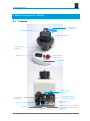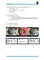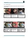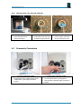
1
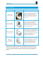
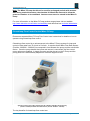
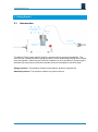
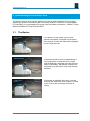
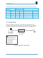
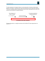
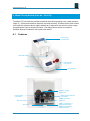
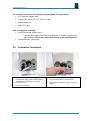
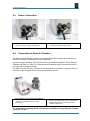
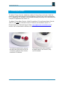
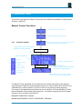
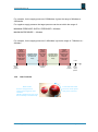
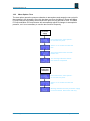
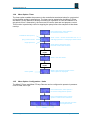
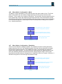
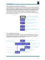
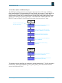
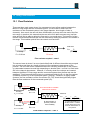
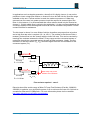
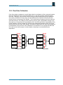
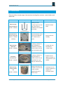
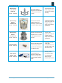
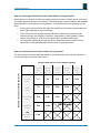
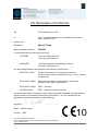
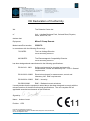
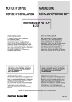
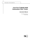
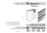
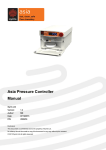
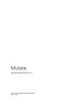
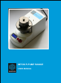
MITOS P-PUMP RANGE USER MANUAL The Dolomite Centre Ltd. Mitos P-Pump range Product name Product picture Product description The Mitos P-Pump provides pulseless liquid flow Mitos P-Pump (Part No. 3200016) with a precise pressure driven pumping mechanism. It operates over a wide pressure range (0-10bar) with excellent response time and accuracy. The Mitos P-Pump Basic provides pulseless Mitos P-Pump Basic (Part No. 3200175) liquid flow with a precise pressure driven pumping mechanism. Connecting to a PC via RS232 serial interface allowing data logging and control using free PC software. The Mitos P-Pump Remote provides pulseless liquid flow operating over a wide pressure range Mitos P-Pump Remote (Part No. 3200176) (0 - 10bar) with excellent response time and accuracy. The design allows users to connect to Dolomite Remote Chambers or custom chambers with a push-click action. The Mitos P-Pump Remote Basic connects to a Mitos P-Pump PC allowing data logging and control using free Remote Basic PC software. The design allows users to (Part No. 3200177) connect to Dolomite Remote Chambers o custom chambers with a push-click action. All four pumps in the Mitos P-Pump range provide pulseless liquid flow with a precise pressure driven pumping mechanism. The pumps operate over a wide pressure range (0-10bar). Please note the Basic versions of the pumps will not work without PC control. MAR-000182_v.1.8 Page 2 of 58 The Dolomite Centre Ltd. Note: The Mitos P-Pump should not be used for prolonged periods with acetone. After being used with acetone, the chamber lid should be removed to allow the pressure chamber to be ventilated. Acetone must never be stored in the Mitos PPump. For more information on the Mitos P-Pump product range please visit our website http://www.dolomite-microfluidics.com/webshop and download our technical datasheets. Closed-loop Flow Control for the Mitos P-Pump Please see separate Mitos P-Pump Flow Control user instructions for details on how to operate using closed-loop flow control. Closed-loop flow control is an enhancement to the Mitos P-Pump system for improved control of flow rates from 70 nl/min to 5 ml/min. It requires that a Mitos Flow Rate Sensor (Part No. 3200096 – 3200100) is connected in-line between the pump and the microfluidic device. Once the pump detects that a flow rate sensor is connected, the flow control menu options are enabled. A target flow rate can then be set on the P-Pump and the pump pressure is automatically adjusted to meet the target flow rate. System for Flow Control: Mitos P-Pump (Part No. 3200016) with Mitos Sensor Display (Part No. 3200095) and Mitos Flow Rate Sensor (Part No. 3200096 – 3200100) The key benefits of closed-loop flow control are: MAR-000182_v.1.8 Page 3 of 58 The Dolomite Centre Ltd. Control flow rates instead of pressure making experiments easier to set-up and optimise. Improved flow rate precision: even better control over introduction of micro-scale reagent volumes. Ideal for droplet generation: higher long-term droplet monodispersity in flow control mode compared with pressure control mode. MAR-000182_v.1.8 Page 4 of 58 The Dolomite Centre Ltd. Contents 1. Important Information 6 2. Getting started 7 2.1 Introduction 3. Understanding Pressure Driven Flow 7 8 3.1 The Basics 8 3.2 General Theory 9 4. Mitos P-Pump (Part No. 3200016) 11 4.1 Features 11 4.2 Fluidic Connection 12 4.2.1 Opening Chamber 12 4.2.2 Inserting Fluid Vial 13 4.2.3 Closing Chamber 13 4.2.4 Adjusting Dip Tube 14 4.3 Pneumatic Connection 14 4.4 Power Connection 15 4.5 Mitos Sensor Unit Electrical Connection 15 5. Mitos P-Pump Basic (Part No. 3200175) 16 5.1 Features 16 5.3 Pneumatic Connection 17 5.4 Power Connection 18 5.5 USB to RS232 Connection 18 5.6 Mitos Sensor Unit Electrical Connection 19 6. Mitos P-Pump Remote (Part No. 3200176) 20 6.1 Features 20 6.2 Pneumatic Connection 21 6.3 Power Connection 22 6.4 Connection to Remote Chamber 22 6.5 Mitos Sensor Unit Electrical Connection 23 7. Mitos P-Pump Remote Basic (Part No. 3200177) 24 7.1 Features 24 7.2 Pneumatic Connection 25 7.3 Power Connection 26 7.4 Connection to Remote Chamber 26 7.5 USB to RS232 Connection 27 7.6 Mitos Sensor Unit Electrical Connection 27 8. Mitos Sensor Units Connection MAR-000182_v.1.8 28 Page 5 of 58 The Dolomite Centre Ltd. 8.1 Standalone device 28 8.2 Connection to the top of the Mitos P-Pump 29 8.3 USB Connection 30 8.4 Electrical Connection 30 9. Controlling the pumps 31 10. Manual User Control 32 10.1 Pressure Control 32 10.2 User Controls 33 10.3 Menu option: Tare 34 10.4 Menu option: Timer 35 10.5 Menu option: Configuration – Units 36 10.6 Menu option: Configuration- Mode 36 10.7 Menu option: Configuration – Resolution 36 10.8 Menu option: Configuration – Calibration 37 10.9 Menu option: Error log 37 10.10 Menu option: USB data export 38 10.11 Menu option: Screensaver 39 10.12 Menu option: Information 39 11 PC Software User Control 9.1.1 9.1.2 Detect devices 40 9.1.1.1 USB Connection 40 9.1.1.2 Connection via a serial cable 40 Using the PC Software 41 12 Using Flow Resistors 13 43 10.1 Flow Resistors 43 10.2 Flow Rate Calibration 45 Accessories 11.1 14 40 Accessories compatibility FAQ 46 48 49 15 Power consumption specification 53 16 CE Declaration of Conformity 54 MAR-000182_v.1.8 Page 6 of 58 The Dolomite Centre Ltd. 1. Important Information Overpressure Warning Do not connect a pressure supply over 11 bar gauge to the Mitos P-Pump range. This may result in failure of the Mitos P-Pump range and injury to the user. Glass Pressure Chamber Warning If the glass pressure chamber is scratched or cracked, do not continue to use the Mitos P-Pump. This may result in failure of the Mitos P-Pump and injury to the user. Please contact Dolomite for replacement of the glass vessel. Maintenance Advice Maintenance should only be attempted by qualified service personnel. Removal of the back panel may invalidate any warranty. Please contact Dolomite for further information. General Advice on Use of Pressure Equipment Care must be taken when the Mitos P-Pump is pressurised to ensure that the unit is not dropped or damaged in any way. Use of Oxygen and flammable gases P-Pump should not be used with Oxygen or flammable gases Eye Protection Safety glasses should be worn at all times when using a Mitos P-Pump. This is due to the use of pressurised equipment and is especially important when hazardous liquids are used. MAR-000182_v.1.8 Page 7 of 58 The Dolomite Centre Ltd. 2. Getting Started 2.1 Introduction atmospheric pressure liquid flow liquid flow chamber pressure The Mitos P-Pump range delivers fluid by a pressure driven pumping mechanism. The user sets the chamber pressure (gauge pressure), which determines the flow rate of liquid from the chamber. When the user vents the chamber (or when the Mitos P-Pump range is switched off) the pressure inside the chamber returns to atmospheric and flow stops. Gauge pressure: The pressure relative to atmospheric pressure (ambient air) Absolute pressure: The pressure relative to a perfect vacuum MAR-000182_v.1.8 Page 8 of 58 The Dolomite Centre Ltd. 3. Understanding Pressure Driven Flow The pressure driven flow concept applies to all pumps within the Mitos P-Pump range, whether the pressure chamber is part of the pump module, i.e Mitos P-Pump and Mitos P-Pump Basic or is connected to the pump via a pneumatic connection, i.e Mitos P-Pump Remote and Mitos P-Pump Remote Basic. 3.1 The Basics HIGH FLOW RATE short tube, large bore water MEDIUM FLOW RATE long tube, small bore water LOW FLOW RATE honey MAR-000182_v.1.8 long tube, small bore If the Mitos P-Pump range is set to 5bar pressure and water is pumped out through a short section of tube, the water will be pumped out at a high flow rate. If the short section of tube is replaced with a very long section of tube with a very small internal diameter, the water flow rate will slow down considerably. Microfluidic channels are equivalent to a tube with a very small internal diameter. If the water is replaced with honey, then the flow rate will slow down even further (if it flows at all). This is due to the high viscosity of honey. Page 9 of 58 The Dolomite Centre Ltd. The following table show the effect of tube length, tube bore and viscosity on flow rate. Effect of tube length on flow rate Effect of tube internal diameter on flow rate Effect of viscosity on flow rate Tube length Flow rate Tube ID Flow rate Viscosity Flow Rate 0.01m Q 1000µm Q 1cP water Q 0.1m Q / 10 100µm Q / 104 10cP salt solution Q /10 1.m Q / 100 10µm Q / 108 10m 100m 3.2 1µm Q / 1000 Q / 10000 0.1µm 100cP light machine oil Q /100 12 1000cP corn syrup Q /1000 16 10000cP thick honey Q /10000 Q / 10 Q / 10 General Theory When using the Mitos P-Pump range, it is important to be aware that the flow rate generated at a chosen pressure is dependent on the flow resistance of the system that you connect to and the viscosity of the fluid. This is illustrated in the diagram below. fluid flow Mitos P-Pump connected system P = 0-10 bar flow resistance Q = _P_ Rs.µ Rs = ƒ(d,L) Key P: pressure set by user (bar) Rs: flow resistance (mm -3) d: tube internal diameter (mm) L: tube length (mm) Q: flow rate (µl/min) µ: viscosity (cP) Flow rate dependence on flow resistance MAR-000182_v.1.8 Page 10 of 58 The Dolomite Centre Ltd. The flow resistance of a length of tube (or circular channel) is a function of the internal diameter and length. A long tube with small internal diameter gives a high flow resistance. This can be calculated with the following formula and used to calculate the flow rate in the system when pumping at a selected pressure. flow rate generated by a selected pressure flow resistance of tube or channel Rs = 6.79x10⁻⁹._L_ d4 Insert into formula Q = _P_ Rs.µ Please note the correct units must be used as defined above Formulae for flow rate calculation For more information on using flow resistors with the Mitos P-Pump range please see section 10. MAR-000182_v.1.8 Page 11 of 58 The Dolomite Centre Ltd. 4. Mitos P-Pump (Part No. 3200016) 4.1 Features Flow sensor module dock Dip tube (liquid outlet) Pressure chamber lid Glass pressure chamber Display screen Twist and click control knob Cancel button Pressure supply connection Power supply connection ON / OFF switch Not used MAR-000182_v.1.8 Mitos Sensor Units electrical connection USB B connection (from PC) USB A connection x 2 (for data download) Mitos Sensor Units connection Page 12 of 58 The Dolomite Centre Ltd. The following accessories are supplied with the Mitos P-Pump: Pneumatic supply cable Tubing FEP 250µm ID, 1/16” OD, 2m length Power supply unit Mains IEC lead User to supply the following: Vessel containing sample liquid o Liquids to be pumped must always be placed in a suitable vial within the glass chamber. Never place any liquid directly in the glass chamber! Compressed air / gas supply 4.2 Fluidic Connection 4.2.1 Opening Chamber LOCKED PUSH DOWN & ROTATE UNLOCKED Locked symbol aligned Two stage opening process Unlocked symbol aligned MAR-000182_v.1.8 1) push down & rotate anticlockwise 2) pull upwards, slight turn anticlockwise & pull upwards to open Page 13 of 58 The Dolomite Centre Ltd. 4.2.2 Inserting Fluid Vial The fluid to be pumped must always be placed inside a small vial and not directly into the chamber! Insert fluid vial Connect dip tube place fluid vial (smaller than Ø30 x H88mm) into chamber insert 1/16” OD tube into chamber lid use vessel holder for small fluid vials leave length of tube protruding and tighten fitting 4.2.3 Guide dip tube into vial as the chamber lid is put in position, ensure that the dip tube is guided into the fluid vial Closing Chamber PUSH DOWN & ROTATE UNLOCKED LOCKED Unlocked symbol aligned MAR-000182_v.1.8 Two stage closing process 1) push down, slight turn clockwise and push down 2) rotate clockwise until lid clicks into position Locked symbol aligned Page 14 of 58 The Dolomite Centre Ltd. 4.2.4 Adjusting Dip Tube (Part No.3200143) UNSAFE SAFE TIGHTEN Adjust dip tube ensure dip tube is below surface of the liquid 4.3 Dip tube free (unsafe) in this state the dip-tube may be ejected at high pressures to ensure safety, retain dip tube by inserting into cleat Pneumatic Connection PUSH IN TO RELEASE CONNECT TO PORT To connect pneumatic supply: Dip tube retained (safe) use pneumatic supply cable (included) to link compressed air / gas supply to the Mitos P-Pump MAR-000182_v.1.8 To disconnect pneumatic supply: turn off compressed air / gas supply first push in sleeve of pressure supply connector to release Page 15 of 58 The Dolomite Centre Ltd. 4.4 Power Connection PUSH IN TO TURN ON Insert power cable only use the power supply unit provided 4.5 1 indicates ON and 0 indicates OFF Mitos Sensor Unit Electrical Connection To connect to Mitos Sensor Unit: Press switch to turn on use electrical cable supplied with the Mitos Sensor Unit The Mitos Sensor Units can also connect to the Mitos P-Pump range via a fluidic connection for more information please see section 8. For more information on Dolomite’s Mitos Sensor Units please visit our website www.dolomite-microfluidics.com/webshop MAR-000182_v.1.8 Page 16 of 58 The Dolomite Centre Ltd. 5. Mitos P-Pump Basic (Part No. 3200175) The Mitos P-Pump Basic connects to a PC via RS232 serial interface allowing data logging and control using free PC software or your own applications. A PC is required to use this pump. 5.1 Features Flow sensor module dock Dip tube (liquid outlet) Pressure chamber lid Glass pressure chamber On/Off switch Pressure supply connection Mitos Sensor Units electrical connection Power supply connection RS232 serial connection to a PC MAR-000182_v.1.8 Page 17 of 58 The Dolomite Centre Ltd. The following accessories are supplied with the Mitos P-Pump Basic: Pneumatic supply cable Tubing FEP 250µm ID, 1/16” OD, 2m length Power supply unit Mains IEC lead User to supply the following: Suitable Windows ™ PC Vessel containing sample liquid o Liquids to be pumped must always be placed in a suitable vial within the glass chamber. Never place any liquid directly in the glass chamber! Compressed air / gas supply For information regarding fluidic connection to the Mitos P-Pump Basic please see 4.2. 5.2 Pneumatic Connection CONNECT TO PORT PUSH IN TO RELEASE To connect pneumatic supply: use pneumatic supply cable (included) to link compressed air / gas supply to the Mitos P-Pump Basic To disconnect pneumatic supply: turn off compressed air / gas supply first push in sleeve of pressure supply connector to release either port can be used MAR-000182_v.1.8 Page 18 of 58 The Dolomite Centre Ltd. 5.3 Power Connection Insert power cable only use the power supply unit provided 5.4 Press button to switch on front of the pump press the button to switch ON USB to RS232 Connection Insert RS232 connector connect USB to PC The Mitos P-Pump Basic connects to a PC via RS232 serial interface allowing data logging and control using free PC software. For PCs that do not support an RS232 serial interface, Dolomite offer a USB adapter cable (Part No. 3200197). MAR-000182_v.1.8 Page 19 of 58 The Dolomite Centre Ltd. 5.5 Mitos Sensor Unit Electrical Connection To connect to Mitos Sensor Unit: use electrical cable supplied with the Mitos Sensor Unit The Mitos Sensor Units can also connect to the Mitos P-Pump range via a fluidic connection for more information please see section 8. For more information on Dolomite’s Mitos Sensor Units please visit our website www.dolomite-microfluidics.com/webshop MAR-000182_v.1.8 Page 20 of 58 The Dolomite Centre Ltd. 6. Mitos P-Pump Remote (Part No. 3200176) The Mitos P-Pump Remote provides pulseless liquid flow operating over a wide pressure range (0 - 10bar) with excellent response time and accuracy. Pressure driven flow is ideal for microfluidic systems where highly stable flow is required in the nl/min to µl/min range for applications such as droplet formation. The design allows users to connect to Dolomite Remote Chambers with a push-click action. 6.1 Features Flow sensor module dock Pneumatic fitting Twist and click control knob Display screen Cancel button Pressure supply connection Power supply connection Mitos Sensor Interface connection ON / OFF switch Not used MAR-000182_v.1.8 USB B connection (from PC) USB A connection x 2 (for data download) Flow Sensor Display Unit connection Page 21 of 58 The Dolomite Centre Ltd. The following accessories are supplied with the Mitos P-Pump Remote: 2 x Pneumatic supply cable Tubing FEP 250µm ID, 1/16” OD, 2m length Power supply unit Mains IEC lead User to supply the following: Vessel containing sample liquid o 6.2 Liquids to be pumped must always be placed in a suitable vial within the glass chamber. Never place any liquid directly in the glass chamber! Compressed air / gas supply Pneumatic Connection PUSH IN TO RELEASE CONNECT TO PORT To connect pneumatic supply: use pneumatic supply cable (included) to link compressed air / gas supply to the Mitos P-Pump Remote To disconnect pneumatic supply: turn off compressed air / gas supply first push in sleeve of pressure supply connector to release either port can be used MAR-000182_v.1.8 Page 22 of 58 The Dolomite Centre Ltd. 6.3 Power Connection PUSH IN TO TURN ON Insert power cable only use the power supply unit provided 6.4 Press switch to turn on 1 indicates ON and 0 indicates OFF Connection to Remote Chamber The Mitos P-Pump Remote features a pneumatic fitting which allows the connection to Dolomite’s Remote Chambers or custom chambers. As shown below, the Mitos P-Pump Remote is connected to the Mitos P-Pump Remote Chamber 30 (Part No. 3200178), a glass pressure chamber which connects securely to the pump via a pneumatic fitting. The Mitos P-Pump Remote Chamber 30 can be placed on a hotplate, magnetic stirrer or incubator to benefit applications requiring temperature control. Connect Mitos P-Pump Remote Chamber 30 connect via provided pneumatic tubing (3m length) Pneumatic tubing is connected to the pump and chamber via a push-click action enabling quick release both ends and reducing downtime between experiments. For information regarding fluidic connection to the Mitos P-Pump Remote Chamber 30 please see 4.2. MAR-000182_v.1.8 Page 23 of 58 The Dolomite Centre Ltd. 6.5 Mitos Sensor Unit Electrical Connection To connect to Mitos Sensor Unit: use electrical cable supplied with the Mitos Sensor Unit The Mitos Sensor Units can also connect to the Mitos P-Pump range via a fluidic connection for more information please see section 8. For more information on Dolomite’s Mitos Sensor Units please visit our website www.dolomite-microfluidics.com/webshop MAR-000182_v.1.8 Page 24 of 58 The Dolomite Centre Ltd. 7. Mitos P-Pump Remote Basic (Part No. 3200177) The Mitos P-Pump Remote Basic connects to a PC via RS232 serial interface allowing data logging and control using free PC software or your own applications. A PC is required to use this pump. For PCs that do not support an RS232 serial interface, Dolomite offers a USB adapter (Part No. 3200197). All the other features of the pump are the same as for the Mitos P-Pump Remote (Part No. 3200177) including pulseless pumping performance and easy to use pneumatic fitting. 7.1 Features Flow sensor module dock Pneumatic fitting On/Off switch Pressure supply connection Mitos Sensor Interface connection Power supply connection RS232 serial connection to a PC MAR-000182_v.1.8 Page 25 of 58 The Dolomite Centre Ltd. The following accessories are supplied with the Mitos P-Pump Remote Basic: 2 x Pneumatic supply cable Tubing FEP 250µm ID, 1/16” OD, 2m length Power supply unit Mains IEC lead User to supply the following: Suitable Windows™ PC Vessel containing sample liquid Compressed air / gas supply 7.2 Pneumatic Connection PUSH IN TO RELEASE CONNECT TO PORT To connect pneumatic supply: use pneumatic supply cable (included) to link compressed air / gas supply to the Mitos P-Pump Remote Basic To disconnect pneumatic supply: turn off compressed air / gas supply first push in sleeve of pressure supply connector to release either port can be used MAR-000182_v.1.8 Page 26 of 58 The Dolomite Centre Ltd. 7.3 Power Connection Insert power cable only use the power supply unit provided 7.4 Press button to switch on Front of the pump press 1 to switch ON USB to RS232 Connection Insert RS232 connector connect USB to PC The Mitos P-Pump Remote Basic connects to a PC via RS232 serial interface allowing data logging and control using free PC software. For PCs that do not support an RS232 serial interface, Dolomite offer a USB adapter cable (Part No. 3200197). MAR-000182_v.1.8 Page 27 of 58 The Dolomite Centre Ltd. 7.5 Connection to Remote Chamber The Mitos P-Pump Remote Basic features a pneumatic fitting which allows the connection to Dolomite’s Remote Chambers or custom chambers. The Mitos P-Pump Remote Basic can connect to the Mitos P-Pump Remote Chamber 30 (Part No. 3200178), a glass pressure chamber which connects securely to the pump via a pneumatic fitting. The Mitos P-Pump Remote Chamber 30 can be placed on a hotplate, magnetic stirrer or incubator to benefit applications requiring temperature control. Connect Mitos P-Pump Remote Chamber 30 connect via provided pneumatic tubing (3m length) Pneumatic tubing is connected to the pump and chamber via a push-click action enabling quick release both ends and reducing downtime between experiments. For information regarding fluidic connection to the Mitos P-Pump Remote Chamber 30 please see 5.2. 7.6 Mitos Sensor Unit Electrical Connection To connect to Mitos Sensor Unit: use electrical cable supplied with the Mitos Sensor Unit MAR-000182_v.1.8 The Mitos Sensor Units can also connect to the Mitos P-Pump range via a fluidic connection for more information please see section 8. Page 28 of 58 The Dolomite Centre Ltd. 8. Mitos Sensor Units Connection The Mitos Sensor Display (Part No. 3200095) and Mitos Flow Rate Sensors (Part No. 3200096-3200100) are compatible with the Mitos P-Pump range for measuring and displaying ultra low liquid rates. The high precision thermal sensor technology provides total media isolation and extremely low internal volume with no moving parts. All measurement data is fully calibrated for water and temperature compensated by means of an internal microcontroller. The Mitos Flow Rate Sensor simply attaches to the Mitos Sensor Display with a push-click action. Once connected to a Flow Rate Sensor, the display can be used as a standalone device (see 8.1) or sit on top of a Mitos P-Pump (see 8.2) By connecting the USB lead of the Sensor Display to a Mitos P-Pump, the display is powered and the Mitos P-Pump records the flow rates which will be stored in a log file within the pump together with the pressure control data (see 8.3). 8.1 Standalone device Fig. 1 Standalone device Mitos Sensor Unit connected to a Mitos P-Pump as a standalone device MAR-000182_v.1.8 Page 29 of 58 The Dolomite Centre Ltd. 8.2 Connection to the top of the Mitos P-Pump Connect tube from Mitos P-Pump to Flow Sensor Fig. 2. Connection to top of a Mitos P-Pump 8.3 Connect Mitos Sensor Unit to the pins on the Mitos P-Pump Connect tube to system Fig. 2. Connection to top of a Mitos P-Pump Connect tubing from a Mitos P-Pump through Mitos Sensor Unit and connect to your system USB Connection Fig. 3. USB Connection to the Mitos P-Pump use USB cable supplied with the Mitos Sensor Unit MAR-000182_v.1.8 Page 30 of 58 The Dolomite Centre Ltd. 8.4 Electrical Connection To connect to Mitos Sensor Unit: use electrical cable supplied with the Mitos Sensor Unit For more information on Dolomite’s Mitos Sensor Units please visit our website www.dolomite-microfluidics.com/webshop MAR-000182_v.1.8 Page 31 of 58 The Dolomite Centre Ltd. 9. Controlling the pumps The Mitos P-Pump (Part No. 3200016) and Mitos P-Pump Remote (Part No. 3200176) feature an intuitive twist-and-click knob and display for manual user control as described in 9.1. Additionally, PC software is also available enabling the pumps to be controlled from a simple PC application see section 10. The Mitos P-Pump Basic (Part No. 3200175) and Mitos P-Pump Remote Basic (Part No. 3200177) can only be controlled via the PC Software as described in section 11. Please contact our Technical Support Team [email protected] to receive a link to download the software online. The pressure pump above features the twist-and-click knob and can be controlled via Manual User Control as well as PC Software. MAR-000182_v.1.8 The pressure pump above features the basic design; user control is only via PC Software. Page 32 of 58 The Dolomite Centre Ltd. 10. Manual User Control This section only applies to Mitos P-Pump (Part No. 3200016) and Mitos P-Pump Remote (Part No. 3200176) Manual Control Functions P-Pump is starting. Please wait. P-Pump is initialising. Please wait. 10.1 Pressure Control current pressure in chamber (relative to atmosphere) Pressure control screen. N/A indicates that no target pressure has been selected. select pressure status indicator default click to access menu pressure target reached error – click to display details target pressure click – scroll – click to select (relative to atmosphere) wait 30 seconds timer mode (section 3.2) Screensaver mode. Scrolls between current pressure and target pressure. The Mitos P-Pump and Mitos P-Pump Remote can operate with positive and negative supply pressure. Maximum positive supply pressure is 11bar and this value should not be exceeded due to safety reasons. There is no limit on the minimum supply pressure. The range of the target pressure that can be set on the Mitos P-Pump and Mitos P-Pump Remote depends on the actual supply pressure. For positive supply pressure the target pressure can be set within the range of: MINIMUM PRESSURE: 20mbars MAXIMUM PRESSURE: SUPPLY PRESSURE - 250mbars MAR-000182_v.1.8 Page 33 of 58 The Dolomite Centre Ltd. For example, for the supply pressure of 3500mbars it gives the range of 20mbars to 3250mbars. For negative supply pressure the target pressure can be set within the range of: MINIMUM PRESSURE: SUPPLY PRESSURE + 80mbars MAXIMUM PRESSURE: – 20mbars For example, for the supply pressure of -800mbars it gives the range of -720mbars to 20mbars. Negative target pressure is limited to 80 mbars more than the actual supply pressure Minimum target pressure limit which is +/- 20 mbars Negative target pressure can be set within this range -20 Negative supply pressure 10.2 0 Positive target pressure can be set within this range Positive target pressure is limited to 250 mbars less than the actual supply pressure 11000 20 Atmospheric pressure Positive supply pressure Max positive supply pressure User Controls Back button Press to stop pressure control press again to vent chamber (NOTE: chamber will also vent if the P-Pump is switched off) MAR-000182_v.1.8 Twist and click knob PRESS PRESS Scroll to menu option and press to access Page 34 of 58 The Dolomite Centre Ltd. 10.3 Menu Option: Tare The tare option opens the pressure chamber to atmosphere and resets the zero point for the pressure in the chamber. Once this has been set, then the Mitos P-Pump and Mitos P-Pump Remote will maintain an accurate zero point for long periods of time. The Mitos P-Pump and Mitos P-Pump Remote will automatically adjust to changes in atmospheric pressure, so it is not necessary to use the tare function frequently. disconnect pneumatic supply In the main menu, select option 1 to reset the zero point. Select “Y” to confirm and start the tare. The process takes a few seconds. Please wait. This message indicates that the tare has been completed. pneumatic supply still connected In the main menu, select option 1 to reset the zero point. Select “Y” to confirm and start the tare. Message indicates that the pneumatic supply is still connected. Disconnect and retry. MAR-000182_v.1.8 Page 35 of 58 The Dolomite Centre Ltd. 10.4 Menu Option: Timer The timer option enables the pressure to be controlled at a selected value for a set period of time before venting to atmosphere. The timer can be started after the Mitos P-Pump and Mitos P-Pump Remote is already controlling at a pressure to vent the chamber in a set period of time. Alternatively, the timer can be used to start and end pressure control. This function is particularly useful in stopping the pump before the sample fluid has been used up. In the main menu, select option 2 to access the timer screen. countdown time (h:m:s) Click – scroll – click to set the time in h : m : s and target pressure. Click play to start control. play / pause control target pressure Click again to pause the timer. Pressure control will continue. press back button Back in the main menu. press back button Back in the pressure control screen. Timer symbol is displayed. timer symbol 10.5 Menu Option: Configuration - Units The Mitos P-Pump and Mitos P-Pump Remote can be configured to operate in pressure units of mbar, bar or psi. In the main menu, select option 3 to access configuration options. In the configuration menu, select option 1 to access unit selection. Scroll and click to select the required units. Scroll MAR-000182_v.1.8 Page 36 of 58 The Dolomite Centre Ltd. 10.6 Menu Option: Configuration - Mode The Mitos P-Pump and Mitos P-Pump Remote have two main modes of use. The first is static mode where the user selects a target pressure and the pump controls to that pressure. This is used in the majority of situations. The second is moving mode where the user dynamically controls the target using the twist-and-click control knob and the pump follows this moving target. This is particularly useful for precise control of liquid movement on a microfluidic chip or for observing the effect of small pressure changes on a system (e.g. droplet generation). In the main menu, select option 3 to access configuration options. In the configuration menu, select option 2 to access mode selection. Scroll and click to select the required mode. Scroll 10.7 Menu Option: Configuration - Resolution There are two resolution settings available. The standard resolution setting allows the target pressure to be set in the smallest possible increment at low pressures, but larger increments at higher pressures. This enables the user to scroll through the pressure range quickly and efficiently. The high resolution setting allows the target pressure to be set in the smallest possible increment across the entire pressure range. This may be required where small pressure changes have a significant effect on a system. However, it will take a long time to scroll through the pressure range. In the main menu, select option 3 to access configuration options. In the configuration menu, select option 3 to access resolution selection. Scroll and click to select the required resolution. Scroll MAR-000182_v.1.8 Page 37 of 58 The Dolomite Centre Ltd. 10.8 Menu Option: Configuration - Calibration The calibration function should be used when the pressure control is more unstable than expected or takes longer than expected to reach the target pressure. Over long periods of time, there may be some degradation in the pressure control and the calibration function will retune the control for optimum performance. The Mitos P-Pump and Mitos P-Pump Remote are factory calibrated to work best with compressed air. If the pumps is to be used with a gas of significantly different density (e.g. Helium) then a calibration is recommended. If the vessel size is changed to operate with the Mitos Remote Chamber 400, a calibration is also required. Block liquid outlet port Before calibrating, the liquid outlet port should be blocked to prevent liquid flow In the main menu, select option 3 to access configuration options. In the configuration menu, select option 4 to perform a calibration. Select “Y” to confirm and start the calibration. Progress towards completion displayed. The calibration takes approximately 20 min. 10.9 Menu Option: Error Log To aid troubleshooting and provide information on issues with the Mitos P-Pump and Mitos P-Pump Remote, there is an error log. In the error log, all the previous messages for this session are recorded. The 3 categories of logged messages are information messages, warning messages and error messages. In the main menu, select option 4 to access the error log. Most recent message is highest number in log Scroll and click on message to view more details. Scroll Day and time are shown. Scroll to read full message. Warning message Error message Information message MAR-000182_v.1.8 Day and time are shown. Scroll to read full message. Day and time are shown. Scroll to read full message. Page 38 of 58 The Dolomite Centre Ltd. 10.10 Menu Option: USB Data Export The USB option allows pressure control data to be exported to a PC using a USB key. Each time the Mitos P-Pump and Mitos P-Pump Remote are turned on, a new data file is created. This data file contains information on the atmospheric pressure (mbar abs), supply pressure (mbar abs), chamber pressure (mbar gauge) and target pressure (mbar gauge). If the pump is left running overnight, a new data file is created at 00:00:00. The Mitos P-Pump and Mitos P-Pump Remote store data from the previous 7 days. insert USB key Symbol indicates USB key is connected In the main menu, select option 5 to access the USB menu. Select COPY to transfer all data files to the USB key. Please wait. Message indicates that data transfer has been completed. To safely dismount the USB key, select REMOVE. The USB can now be safely removed. USB not connected In the main menu, select option 5 to access the USB menu. Indicates no USB key is connected. Insert USB key and retry. The pressure control data files are contained in a folder named “logs”. The file names are in the format “PressurePumpDataLog_Year_Month_Date_Time.csv” and files can be opened with Microsoft Excel. MAR-000182_v.1.8 Page 39 of 58 The Dolomite Centre Ltd. 10.11 Menu Option: Screensaver The screensaver option allows the user to enter the screensaver mode manually. In the main menu, select option 6 to access the screensaver mode. Screensaver mode. Scrolls between current pressure and target pressure. 10.12 Menu Option: Information This menu option provides information on the software version and the current atmospheric, chamber and supply pressure readings. In the main menu, select option 7 to access the information mode. Scroll to view info. Pressure readings update when scrolling. Scroll MAR-000182_v.1.8 Page 40 of 58 The Dolomite Centre Ltd. 11. PC Software User Control 11.1 Detect devices 11.1.1 USB connection Mitos P-Pump and Mitos P-Pump Remote pumps connect to your PC via a standard USB cable. The pump will be automatically detected by the PC Software as soon as the PC Software has been started on the PC. Users can also connect/disconnect pumps after the PC Software has been started. In that case the devices still get detected automatically but the detection might take up to 15 seconds. 11.1.2 Connection via a serial cable Mitos P-Pump Basic and Mitos P-Pump Remote Basic connect to your PC via a serial (RS232) cable or USB to RS232 adapter cable. 1) USB to RS232 cable If the pump is connected using Dolomite’s USB to RS232 Adaptor Cable (Part No. 3200197) all devices will be detected automatically by the PC software and shown in the “P-Pumps” section (see point 9.1.2). 2) Serial converter and serial cables If the pump is connected via a generic serial converter or to a serial port, the devices will not be detected automatically but have to be added manually following the step-by-step process below: 1. Start the PC Software and open the “Devices” section 2. Click on the following icon (top left corner) to show all COM ports connected to the PC which might take up to 15 seconds 3. Select the COM port that connects the pump to the PC 4. If the serial converter or serial cable you are using offers more than one COM port you might need to select all ports/try the different COM ports to identify the right port that connects the pump to the PC 5. The PC Software will scan the COM port/ports selected which might take a couple of seconds 6. After the scanning has been completed, the COM port which connects the pump to the PC will disappear from the COM ports list and the pump will be shown in the “P-Pumps” section MAR-000182_v.1.8 Page 41 of 58 The Dolomite Centre Ltd. 11.2 Using the PC software The PC Software offers 3 sections as shown below: 1) Devices This section allows users to monitor and set the target and chamber pressure of the pump. It is divided into a “P-Pumps” section showing all pumps connected to the PC Software and “Flow Sensors” section showing all Flow Sensors connected to the PC Software. Toolbox icons Start Remote Control Stop Remote Control Tare Pump and Flow Sensor Tare Pump Tare Flow Sensor Erase chart data Save chart data to csv.file Please note: Some of the above icons might be hidden due to the type of pump you are using and the pump state. When connecting the Mitos P-Pump or Mitos P-Pump Remote to the PC Software, the Connection Status will automatically change to “Being Controlled” and the pump display will show “PC CTL” as shown below. MAR-000182_v.1.8 Page 42 of 58 The Dolomite Centre Ltd. This will automatically disable the twist-and-click-knob of the pumps and the pumps can only be controlled via the PC Software. Change the PC control mode to Pump control mode To control the pump via the twist-and-click-knob and display and use the PC Software for data log only, select (Stop Remote Control). The Connection Status of the pump will change automatically from “Being Controlled” to “Not Being Controlled”. Remote control can be enabled at any time by selecting (Start Remote Control). You can also exit the PC control mode via the pump as shown below: Press button to exit PC mode Select Y for Yes and press button to confirm exit Please note: The Mitos P-Pump Basic and Mitos P-Pump Remote Basic do not offer a twist-and-click-knob for advanced control. When connecting these pumps to the PC Software the Connection Status will always be “Being Controlled”. The toolbox icons “Start Remote Control” and “Stop Remote Control” will be hidden. 2) Logs This section displays all important events such as control commands sent to the pump/pumps, connection/disconnection of a device or device errors. 3) Help This section contains a link to Dolomite’s website and allows users to access and download the Mitos P-Pump datasheet. MAR-000182_v.1.8 Page 43 of 58 The Dolomite Centre Ltd. 12. Using Flow Resistors 12.1 Flow Resistors There are three main cases where it is necessary to insert a flow resistor between the Mitos P-Pump range and the connected system. The first case is where the flow resistance of the connected system is low (large diameter, short length of tube or channels). As a result, the user will have limited ability to pump at the low end of the flow rate range. In practice, this means that the user will not be able to access very low flow rates and will not be able to adjust the flow rate in very small steps. The benefit of a flow resistor is that the desired flow rate can be achieved by setting a pressure in the middle of the range. This enables optimal flow rate control and resolution. fluid flow Rf flow resistor P-Pump P = 0-10 bar Q = ___P___ (Rf+Rs).µ connected system Rs is low Flow resistor required – case 1 The second case is where 2 or more immiscible fluids of different viscosities are pumped into a junction and there is a length of channel (flow resistance) downstream of the junction. The flow rate will be unstable because the viscosity downstream of the junction (µs) alternates between low and high depending on whether fluid 1 or fluid 2 or both fluids are in the channel downstream. However, if correctly sized flow resistors are inserted between the Mitos P-Pump range and the connected system then the flow rate can be stabilised. This is because the flow rate is now determined by the R.µ in the flow resistor (constant) and the R.µ in the connected system (varying). Therefore, for highly stable systems, the flow resistance of the flow resistor (Rf1, Rf2) should be significantly higher than the flow resistance of the connected system (Rs). low viscosity fluid P-Pump Rf1 flow resistor flow rate would be unstable without flow resistors Rf1 >> Rs P1 = 0-10 bar fluid flow connected system high viscosity fluid P-Pump P2 = 0-10 bar Rf2 flow resistor Rs downstream of junction produces flow instability Rf2 >> Rs Q = ___P1___ + ___P2_____ Rf1.µ1+Rs.µs Rf2.µ2+Rs.µs µs varies depending on whether fluid 1 or fluid 2 or both fluids are in the channel downstream of the junction Flow resistor required – case 2 MAR-000182_v.1.8 Page 44 of 58 The Dolomite Centre Ltd. In applications such as droplet generation, where fluid 2 is highly viscous, it may not be possible to insert a large flow resistor on channel 2 since this will limit the flow rate range available to the user. If a flow resistor is used, the maximum pressure of 10bar may generate low flow rates, but greater pressure would be required to access higher flow rates. In this instance, it is recommended that a flow resistor should only be inserted on channel 1. If highly stable flow is critical to the application, it is also recommended that the connected system should be designed to have as low flow resistance as possible. Please contact Dolomite for assistance. The third case is where 2 or more fluids of similar viscosities are pumped into a junction and a high flow rate ratio is required (10:1 to 100:1). The problem is that there will be a tendency for back flow into the channel with the lower flow rate. This can be resolved by inserting flow resistors between the Mitos P-Pump range and the connected system to make flow through the connected system the path of least resistance. Ideally, the flow resistance of the flow resistor (Rf1, Rf2) should be higher than the flow resistance of the connected system (Rs). high flow rate P-Pump P1 = 0-10 bar Rf1 flow resistor Rf1 > Rs fluid flow connected system low flow rate P-Pump P2 = 0-10 bar Rf2 flow resistor Q = ___P1___ + ___P2_____ Rf1.µ1+Rs.µs Rf2.µ2+Rs.µs back flow may occur without flow resistors Rf2 > Rs Flow resistor required – case 3 Dolomite also offers a wide range of Mitos P-Pump Flow Resistors (Part No. 3200028 – 3200032) to optimize your microfluidic system, from a minimum flow rate of 0.01µl/min to a maximum flow rate of 1000µl/min. For more information please visit our website http://www.dolomite-microfluidics.com/webshop MAR-000182_v.1.8 Page 45 of 58 The Dolomite Centre Ltd. 12.2 Flow Rate Calibration If the flow resistor resistance is much higher than the resistance of the connected system, then the resistance of the connected system (Rs.µs) can be ignored in determining the flow rate. Therefore, the flow rate from the pump is directly proportional to the pressure. As a result, the Mitos P-Pump range can be calibrated for a specific fluid with the flow resistor before connecting to the system. This is achieved by measuring the flow rate at a selected pressure. Any change in the pressure will then give a predictable change in the flow rate (e.g. if the pressure is increased by 20%, the flow rate will be increased by 20%). In this situation, we can consider the pumps to be independent because they will not be affected by flow rates from other pumps. It should be noted that if the main flow resistance is downstream of the junction, then variations in the pressure of one pump will affect the flow rate from all other pumps. In this situation, the pumps can be described as dependent. Pump 1 Pump 2 flow rate varied constant Rf1 Pump 1 Rf2 Pump 2 flow rate varied varies system constant Pump 3 Rf3 Rs system varies constant Pump 4 varies Rf4 Independent MAR-000182_v.1.8 Rs Pump 3 Pump 4 Dependent Page 46 of 58 The Dolomite Centre Ltd. 13. Accessories Dolomite offers a broad range of accessories including flow resistors, vessel holders and starter kits. Product Name Product picture Description Advantages Enabling the Mitos Mitos P-Pump P-Pump range to be used Vessel Holder Kit with a wide range of (Part No. 3200017) standard and non-standard Minimizes sample waste fluid vessels. Flow Resistor F1, The Flow Resistors can be F3, F10, F30, F100 used to insert additional (Part No. 3200028 flow resistance into a - 3200032) Prevents flow rate instability system. Containing a selection of Mitos P-Pump tubing and fittings to To begin test work Starter Kit enable fluidic connection with the Mitos (Part No. 3200033) between a Mitos P-Pump P-Pump range and a microfluidic system. Containing a selection of Pneumatic Connector Kit (Part No. 3200034) fittings and tubing to Enables fast and reliable connection of enable connection of your compressed air or gas compressed air or gas supplies supply to a Mitos P-Pump Mitos P-Pump 3-way Chamber Lid (Part No. 3200044) MAR-000182_v.1.8 The Mitos P-Pump 3-way Chamber Lid can be used to pump 3 liquids simultaneously from a Providing a low cost method of delivering 3 reagents to a microfluidic system Mitos P-Pump. Page 47 of 58 The Dolomite Centre Ltd. Mitos P-Pump 3-way Vessel Holder Kit (Part No. 3200045) This Vessel Holder is when using the Mitos designed to accommodate P-Pump for 3-channel 3 micro tubes in a Mitos pumping P-Pump. Mitos P-Pump The Remote Chamber Remote enables greater input Chamber 400 volumes up to 400 ml to be (Part No. 3200043) used with a Mitos P-Pump. Mitos P-Pump The Mitos P-Pump Remote Remote Chamber 30 is a 0 - 10bar Continuous pumping Option for heating and magnetic stirring (Part No. 3200178) Sample volumes from 100µl to 30ml Option for heating and magnetic stirring lockable glass pressure chamber. Easy to view sample liquid levels Chamber 30 Improves ease of use Easy to view sample liquid levels Dip Tube Fitting (Part No. 3200143) strain relief The Dip Tube Fitting allows users to easily connect a Adapter Cable (Part No. 3200197) For PCs that do not support an RS232 serial Compatible with 1/16 OD tubing and 1/4-28 dip tube into a fluid vessel flat bottom ports on a Mitos P-Pump. USB to RS232 Featuring an in-built Allowing users to connect their Mitos P-Pump Basic or interface, Dolomite offers Mitos P-Pump a USB to RS232 Adapter Remote Basic to a PC Cable. MAR-000182_v.1.8 Page 48 of 58 The Dolomite Centre Ltd. 13.1 Accessories compatibility Accessories Mitos P-Pump Mitos P-Pump Basic Mitos P-Pump Remote Mitos P-Pump Remote Basic * * * * Mitos P-Pump Starter Kit (Part No. 3200033) * * Pneumatic Connector Kit (Part No. 3200034) * * Mitos P-Pump Vessel Holder Kit (Part No. 3200017) Flow Resistor F1, F3, F10, F30, F100 (Part No. 3200028 - 3200032) Mitos P-Pump 3-way Chamber Lid (Part No. 3200044) Mitos P-Pump 3-way Vessel Holder Kit (Part No. 3200045) Mitos P-Pump Remote Chamber 400 (Part No. 3200043) Mitos P-Pump Remote Chamber 30 (Part No. 3200178) Dip Tube Fitting (Part No. 3200143) USB to RS232 Adapter Cable (Part No. 3200197) * Accessories can only be used with the pumps when used with Mitos P-Pump Remote Chamber 30 MAR-000182_v.1.8 Page 49 of 58 The Dolomite Centre Ltd. 14. FAQ’S Why can’t I select a target pressure? Please check you have connected a compressed air / gas supply correctly (see section 4.4). Why can’t I select a target pressure as high as my supply pressure? To ensure quick response times, the maximum target pressure available is limited to 250 mbar below supply pressure. Why is the chamber pressure not reaching the target pressure? If your target is near supply pressure, then the cause may be fluctuation in your compressed air / gas supply. Please select a lower target or increase your supply pressure. If you target is near atmospheric pressure, then the cause may be an incorrect zero point. Please use the tare function (see section 10.4). Why is the chamber pressure not stabilizing? If there is significant fluctuation in the supply pressure, then it will be difficult for the chamber pressure to reach a stable value. Also, when very high flow rates are used, the Mitos P-Pump must constantly adjust the flow of air / gas into the chamber and some instability may be unavoidable. Can I put my liquid directly in the chamber? No. You must always put the liquid to be pumped into a suitable vial and place this within the glass pressure chamber. Why is the tare function not working? Please ensure your compressed air / gas supply has been disconnected. If you have already disconnected your compressed air / gas supply, then air may be trapped in the pneumatic supply connector. Please connect and disconnect the pneumatic supply cable to vent this trapped air. MAR-000182_v.1.8 Page 50 of 58 The Dolomite Centre Ltd. Why is there pressure in the chamber when I close the chamber lid? The process of putting the chamber lid on compresses the air in the chamber slightly. This can be avoided by ensuring that the dip tube fitting is not tightened until after the chamber lid has been closed. Alternatively, the chamber can be vented after the chamber lid has been closed by pressing the back button. Why can’t I remove the chamber lid easily? If the chamber is pressurised, then the lid cannot be removed as the pressure locks the chamber. Please vent the chamber before attempting to remove the lid. If the chamber lid is difficult to turn, then it is recommended to apply a small amount of silicone grease to the o-ring inside the chamber lid. For further advice on opening the chamber, please see section 4.3.1. Will the flow rate obtained be affected by changes in atmospheric pressure? No, the Mitos P-Pump range automatically adjusts the absolute pressure in the chamber to maintain a constant gauge pressure (pressure relative to atmospheric pressure). How do I know what flow rate the fluid is flowing at? Either a flow sensor is required or the system can be calibrated for a selected fluid, so that a pressure can be translated into a flow rate. Please contact Dolomite for further advice. Why is there backflow into my Mitos P-Pump? When pumping 2 or more liquids using a Mitos P-Pump there is the possibility of backflow from one pump at higher pressure to another pump at lower pressure. This can be prevented by taking the following steps: 1) Connect a flow resistor between the Mitos P-Pump range and the chip for each liquid. The flow resistor should be selected so that all liquids are flowing at approximately the same flow rate at a pressure of 1bar. (See flow resistor selection below). 2) Ideally the flow resistance before the junction (where 2 or more liquids meet) should be greater than the flow resistance after the junction. 3) Before connecting to the chip, it is recommended to prime the inlet tubing. This is achieved by flowing liquids through until they reach the edge connector and waiting until air bubbles have also been flushed through. The Linear Connector can then be connected to the chip. 4) Initially, set all Mitos P-Pumps to the same pressure e.g. 1bar. Then, gradually adjust the pressures of the pump channels to obtain the flow required. MAR-000182_v.1.8 Page 51 of 58 The Dolomite Centre Ltd. How do I avoid gas dissolution in the liquid which is being pumped? Some liquids can absorb air when put under pressure and then release the air in the form of bubbles when the pressure is reduced. This occasionally causes problems with bubbles appearing after a flow resistor or a constriction. To avoid this issue the following can be done: If the system can be set-up with less flow resistance and lower pressure then the level of gas dissolution can be reduced. The P-Pump can be fed with pressurised Helium rather than pressurised air. Helium has very low solubility in liquids in comparison to other gasses. Please ensure the P-Pump is used in a fume hood when operating with Helium. An immiscible liquid such as light oil can be dispensed onto the surface of the liquid that is being pumped to provide a barrier for gas dissolution. How do I select the correct flow resistor for my system? The flow resistor should be selected based on the desired flow rate and the viscosity of the selected liquid using the table below. Dynamic viscosity of selected liquid (cP) Desired flow rate at 1 bar pressure (µl/min) 1 3 10 30 100 Flow rate range Flow rate range Flow rate range Flow rate range Flow rate range 0.01 – 10 0.03 – 30 0.1 – 100 0.3 – 300 1 – 1000 F1 F3 F10 F30 F100 F3 F10 F30 F100 F10 F30 F100 F30 F100 1 e.g. water at 20 ºC 3 blood at 37 ºC 10 25% wt CaCl sol. at 20 ºC 30 vegetable oil Out of range at 40 ºC 100 light machine oil F100 at 20 ºC MAR-000182_v.1.8 Page 52 of 58 The Dolomite Centre Ltd. Why are the flow rates unstable in my system? If you pumping 2 or more fluids into a junction and there is significant flow resistance downstream of the junction, then a flow resistor may be required (see section 10.1). Please contact Dolomite for further advice. 15. Power consumption specification The maximum power consumption for the P Pump range is 40 Watts (1.67 Amps at 24 Volts). MAR-000182_v.1.8 Page 53 of 58 The Dolomite Centre Ltd. CE Declaration of Conformity In accordance with EN 45014:1998 We The Dolomite Centre Ltd of Unit 1, Anglian Business Park, Orchard Road, Royston, Herts, SG8 5TW, UK declare that: Equipment Mitos P-Pump Model name/Part number 3200016 in accordance with the following Directive(s): 73/23/EEC The Low Voltage Directive and its amending directives 89/336/EEC The Electromagnetic Compatibility Directive and its amending directives has been designed and manufactured to the following specifications: EN 61010-1: 2001 Safety requirements for electrical equipment for measurement, control and laboratory use – Part 1: General requirements EN 61326-2-2:2006 Electrical equipment for measurement, control and laboratory use. EMC requirements EN 61000-4-3:2002 EMC – Immunity EN 55022:2006 EMC – Radiated current emissions I hereby declare that the equipment named above has been designed to comply with the relevant sections of the above referenced specifications. The unit complies with all applicable essential requirements of the Directives. Signed by: ....................................................................... Name: Andrew Lovatt Position: CEO 10 Done at The Dolomite Centre Ltd Unit 1, Anglian Business Park, Orchard Road, Royston, Herts, SG8 5TW, UK on 8th March 2010 MAR-000182_v.1.8 Page 54 of 58 The Dolomite Centre Ltd. CE Declaration of Conformity In accordance with EN 45014:1998 We The Dolomite Centre Ltd of Unit 1, Anglian Business Park, Orchard Road, Royston, Herts, SG8 5TW, UK declare that: Equipment Mitos P-Pump Basic Model name/Part number 3200175 in accordance with the following Directive(s): 73/23/EEC The Low Voltage Directive and its amending directives 89/336/EEC The Electromagnetic Compatibility Directive and its amending directives has been designed and manufactured to the following specifications: EN 61010-1: 2001 Safety requirements for electrical equipment for measurement, control and laboratory use – Part 1: General requirements EN 61326-2-2:2006 Electrical equipment for measurement, control and laboratory use. EMC requirements EN 61000-4-3:2002 EMC – Immunity EN 55022:2006 EMC – Radiated current emissions I hereby declare that the equipment named above has been designed to comply with the relevant sections of the above referenced specifications. The unit complies with all applicable essential requirements of the Directives. Signed by: ....................................................................... Name: Andrew Lovatt Position: CEO 11 Done at The Dolomite Centre Ltd Unit 1, Anglian Business Park, Orchard Road, Royston, Herts, SG8 5TW, UK on 8th September 2011 MAR-000182_v.1.8 Page 55 of 58 The Dolomite Centre Ltd. CE Declaration of Conformity In accordance with EN 45014:1998 We The Dolomite Centre Ltd of Unit 1, Anglian Business Park, Orchard Road, Royston, Herts, SG8 5TW, UK declare that: Equipment Mitos P-Pump Remote Model name/Part number 3200176 in accordance with the following Directive(s): 73/23/EEC The Low Voltage Directive and its amending directives 89/336/EEC The Electromagnetic Compatibility Directive and its amending directives has been designed and manufactured to the following specifications: EN 61010-1: 2001 Safety requirements for electrical equipment for measurement, control and laboratory use – Part 1: General requirements EN 61326-2-2:2006 Electrical equipment for measurement, control and laboratory use. EMC requirements EN 61000-4-3:2002 EMC – Immunity EN 55022:2006 EMC – Radiated current emissions I hereby declare that the equipment named above has been designed to comply with the relevant sections of the above referenced specifications. The unit complies with all applicable essential requirements of the Directives. Signed by: ....................................................................... Name: Andrew Lovatt Position: CEO 11 Done at The Dolomite Centre Ltd Unit 1, Anglian Business Park, Orchard Road, Royston, Herts, SG8 5TW, UK on 8th September 2011 MAR-000182_v.1.8 Page 56 of 58 The Dolomite Centre Ltd. CE Declaration of Conformity In accordance with EN 45014:1998 We The Dolomite Centre Ltd of Unit 1, Anglian Business Park, Orchard Road, Royston, Herts, SG8 5TW, UK declare that: Equipment Mitos P-Pump Remote Basic Model name/Part number 3200177 in accordance with the following Directive(s): 73/23/EEC The Low Voltage Directive and its amending directives 89/336/EEC The Electromagnetic Compatibility Directive and its amending directives has been designed and manufactured to the following specifications: EN 61010-1: 2001 Safety requirements for electrical equipment for measurement, control and laboratory use – Part 1: General requirements EN 61326-2-2:2006 Electrical equipment for measurement, control and laboratory use. EMC requirements EN 61000-4-3:2002 EMC – Immunity EN 55022:2006 EMC – Radiated current emissions I hereby declare that the equipment named above has been designed to comply with the relevant sections of the above referenced specifications. The unit complies with all applicable essential requirements of the Directives. Signed by: ....................................................................... Name: Andrew Lovatt Position: CEO 11 Done at The Dolomite Centre Ltd Unit 1, Anglian Business Park, Orchard Road, Royston, Herts, SG8 5TW, UK on 8th September 2011 MAR-000182_v.1.8 Page 57 of 58 The Dolomite Centre Ltd. MAR-000182_v.1.8 Page 58 of 58