1
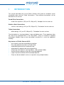
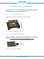
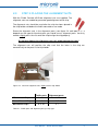
FLUIDIC CONNECT 4515
User Manual - Version 1.1
Visiting address Colosseum 15 · 7521 PV Ensched e Pos tal address P.O. Box 214 · 7500 AE Enschede · The Netherlands
Phone +31 53 850 6 850 Fax +31 53 850 6 8 51 E-mail [email protected] Internet www.micronit.com
CONTENTS
1
INTRODUCTION........................................................................................................... 3
2
ASSEMBLY AND ADJUSTMENTS .......................................................................... 4
2.1
Step 1: Parts check................................................................................................... 4
2.2
Step 2: Chip Placement ........................................................................................... 4
2.3
Step 3: Placing the Alignment Nuts........................................................................ 5
2.4
Step 4: Connection of Fittings ................................................................................. 6
3
FRAME .........................................................................................................................11
4
QUESTIONS AND ANSWERS ................................................................................12
5
TIPS AND TRICKS FOR CONNECTION ...............................................................14
5.1
Tightening force.......................................................................................................14
5.2
Stainless Steel / Teflon Connection Kit ...............................................................15
6
7
SPECIFICATIONS......................................................................................................16
6.1
Fluidic Connect 4515..............................................................................................16
6.2
Fluidic Connections ................................................................................................16
6.3
Fluidic Slide..............................................................................................................17
PARTS LIST................................................................................................................18
User Manual - Fluidic Connect 4515
2
1
INTRODUCTION
This manual describes the use of Fluidic Connect 4515 and the installation of the
microfluidic chips and the Fluidic Connections. Three different connections will be
described in this manual:
Fused Silica Connections
•
fused silica capillaries (375 µm OD, 150 µm ID), ‘Nanoport’ ferrules and nuts
Stainless Steel Connections
•
stainless steel tubing (1/16” µm OD, 250 µm ID), ‘Flat-bottom’ ferrules and nuts
Teflon Connections
•
teflon tubing (1/16” µm OD, 250 µm ID), ‘Flat-bottom’ ferrules and nuts
The chip holder has viewing windows in top and bottom parts. These openings allow
the chip to be inspected while in the chip holder, using an inverted or standard
microscope. Multiple chips can be connected in parallel or in series for additional
flexibility.
Key features of Fluidic Connect 4515:
•
•
•
•
•
•
•
•
User friendly, leak-free microfluidic connections
Easy chip replacement thanks to Fluidic Slide
Improved alignment of the microfluidic chip
Improved chip support to prevent chip breaking
Chemically inert materials (sealing rubbers, chip and chip holder)
Smaller distance between chip and microscope objective
Larger chip area to detect with microscope objective
Chips can be connected in series or in parallel using multiple holders
User Manual - Fluidic Connect 4515
3
2
ASSEMBLY AND ADJUSTMENTS
In this section, the assembly of the chip holder will be discussed step by step. Please
pay attention to step 4, as this step contains two different assembly methods,
depending on the type of Fluidic Connection Kit that is used.
2.1
STEP 1: PARTS CHECK
Check the parts list on page 17 to see if all the parts are included.
Figure 2.1. All the parts of Fluidic Connect 4515
2.2
STEP 2: CHIP PLACEMENT
Clean the chip holder and place the chip in the chip holder. The user-friendly design
allows the user to push (slide) the chip into the chip holder over a flat surface (see
figure 2.2). Make sure that the arrow on the chip cartridge directs to the left.
Figure 2.2. Slide the chip into the chip holder
User Manual - Fluidic Connect 4515
4
2.3
STEP 3: PLACING THE ALIGNMENT NUTS
With the Fluidic Connect 4515 two alignment nuts are supplied. The
alignment nuts are needed to guarantee good alignment of the chip.
The alignment nuts should be used after the chip has been placed in
the chip holder and before the fluidic connections are made.
Screw the alignment nuts in the alignment ports (see figure 2.3 and table 2.1). It
depends on the type of chip what ports you should use as alignment ports. You only
need to slightly press the nuts onto the chip to align the chip properly.
Do not over tighten the alignment nuts; this might damage the chip!
The alignment nuts will position the chip such that the holes in the chip are
concentrically to the ports in the chip holder.
11
4 5
6 7
2 1
10 9
8
3
Figure 2.3. Screw the alignment nuts slightly into the chip holder
Fluidic ports
Microreactor Chips
Alignment ports
2, 4, 8
3, 7
Cross Channel Chips
1, 3, 5, 8
2, 7
Micromixer Chips
6, 8, 10
3, 7
Table 2.1. Fluidic ports and alignment ports per chip type
User Manual - Fluidic Connect 4515
5
2.4
STEP 4: CONNECTION OF FITTINGS
Now the fluidic connections can be made. Since different connection types require
different procedures, the connection procedures are described separately below. The
procedure for the fused silica connections is described in Step 4A, for the teflon and
stainless steel connections the description can be found in Step 4B.
2.4.1
STEP 4A - FUSED SILICA CONNECTION KIT
Step 4A is specifically for the Fused Silica Connection Kit.
1.
Adjusting capillary length
The “Nanoport” ferrules and nuts supplied with the Fused Silica Connection Kit
enable low dead-volume connections, using fused silica capillary tubing of 375
µm outer diameter.
Various tools are available for cutting capillaries to the required length. The
capillary can be cut with a straight edge using a dedicated tool. A well-defined cut
is important in order to minimize the dead volume in the connection between the
capillary and the chip. Alternatively, the capillary can be cut using a sharp knife.
Fused silica capillaries have a protective polyimide coating on the outside (see
Figure 2.4). A scratch can be made into the silica by cutting through the coating
with a sharp blade (Figure 2.5). When bending the capillary it will break at the
scratch. This is an easy way to cut the capillary to the required length. Note that
the end of a capillary that is cut using the above procedure generally is not
completely straight (Figure 2.6), unlike the end of a pre-cut and polished
capillary. The latter are commercially available from various capillary tubing
suppliers.
Figure 2.4. Fused silica with a polyimide coating
User Manual - Fluidic Connect 4515
6
Figure 2.5. Cutting the capillary
2.
Figure 2.6. Capillary that has been cut
Connecting the ferrules
After cutting the capillaries to length, the ferrules need to be added. First slide the
nut over the capillary (Figure 2.7.1) followed by the sealing ferrule. The conical
side of the ferrule should be flush with the tip of the capillary (Figure 2.7.3). The
capillary should not protrude (figure 2.7.2).
It is advised to use latex gloves during handling, in order to prevent
contamination of the ferrules. Also rinse the ferrules with deionized (DI) water to
make sure they are clean. The ferrules are made of PERLAST™. This material is
chemically resistant to most solvents.
Figure 2.7.1. Fitting over cap
Figure 2.7.2. Wrong
Figure 2.7.3. Like this
After fitting the ferrules onto the capillary, the capillary should be rinsed to
remove any glass particles resulting from cutting the capillary. Filtered deionized
(DI) water is advised for flushing the capillary.
User Manual - Fluidic Connect 4515
7
3.
Making fluidic connections
At this stage you can place the fittings in the appropriate fluidic ports (see table
2.1). The fittings can be tightened individually by hand using a special extender
tool (Figure 2.8).
Figure 2.8. Using the extender tool for tightening the fittings
4.
Visual check
A visual inspection of the conical sealing rubbers can be performed, revealing if
the ferrules properly fit inside the chip holes and to confirm that the capillaries are
aligned directly above the channels (Figure 2.9).
Channel
Capillary
Sealing rubber
Figure 2.9. Capillary correctly positioned above the channel
When sealing with the conical side inside the hole (which is optional), the
intensity of the colour of the seal will change by tightening the fittings. The reason
for this is the increasing contact area between the sealing rubber and the
sidewall of the hole.
User Manual - Fluidic Connect 4515
8
2.4.2
STEP 4B TEFLON OR STAINLESS STEEL CONNECTION KIT
Step 4B is specifically for the Teflon or the Stainless Steel Connection Kit.
1.
Assembling the fittings
The procedure is basically the same for stainless steel as for teflon tubing. It is
advised to clean the chip holder before assembling, and in particular the fitting
assembly hole (port no. 11). Particles can damage the ferrule. Before cleaning
the chip holder, separate the top from the bottom part using the Allen key.
For the assembly, slide the nut, steel compression ring and ferrule (in that order)
onto the tubing. The flattened end of the ring should face towards the nut with the
narrow end of the ferrule towards the ring (Figure 2.10). For the untrained eye it
can be hard to determine which side is narrower, so double check if you are not
sure. The metal ring should be pushed onto the ferrule, in that way ensuring
concentricity of ferrule and ring (Figure 2.11).
Figure 2.10. Fittings order
Figure 2.11. Ensure concentricity of compression
ring and ferrule
Press the tubing and ferrule to the bottom of the fitting assembly hole (port
number 11) in the chip holder while tightening down the nut (figure 2.12). Tighten
comfortably finger-tight. You may use the extender tool to tighten some more,
however be sure not to over tighten the ferrule.
Figure 2.12. Threaded hole for the assembly of Flat-bottom fittings
User Manual - Fluidic Connect 4515
9
2.
Visual check
Check if the compression ring and ferrule are properly mated as shown in Figure
2.13.
Figure 2.13. Proper assembly of compression ring and ferrule
3.
Making fluidic connections
Tighten the fitting in the appropriate fluidic ports (see table 2.1) by using the
extender tool as shown in Figure 2.14. No extreme force should be necessary.
Figure 2.14. Tightening the connection
User Manual - Fluidic Connect 4515
10
3
FRAME
The Fluidic Connect 4515 is supplied with an inverter frame. The chip holder frame
can be used for easy inspection of the chip from the bottom. The chip holder can be
placed upside down in the frame (Figure 3.1). Connect the tubing to any auxiliary
equipment. The chip holder frame allows the tubing to be guided straight down or to
the sides.
Figure 3.1. Chip holder upside down in the chip holder frame
Key features of the inverter frame:
•
•
•
•
The frame is user friendly
Chemical resistance is limited
Zooming in on the channel is still possible
No special tools needed
User Manual - Fluidic Connect 4515
11
4
QUESTIONS AND ANSWERS
This section contains some frequently asked questions.
There are some air bubbles in the connection, how do I remove them?
To prevent air bubbles getting trapped between the connections, it can be helpful
to put some DI water or a bit of the sample fluid in the holes of the chip before
making the connections. When the sealing rubbers are placed, excess liquid will
be pressed out of the holes. The connection will be bubble free.
There is no liquid flow.
Check to make sure that the channel is not obstructed by the sealing rubbers.
This is possible when the Nanoport fittings are tightened too much and the
Nanoport ferrules are used with the conical side pressed in the chip hole.
Release the fittings slightly and check whether a flow is present. It is also
possible that the sealing rubbers are damaged and that they need to be replaced.
The connection leaks during testing.
When the sealing rubbers do not fit straight in the chip holes or on top op the
glass, there can be a leakage. Assemble the chip holder again, following the
instruction on the previous pages.
The dead volume seems to increase.
When the bottom side of the sealing rubber is damaged, it will increase the dead
volume in the connection. The area of contact between the sealing rubber and
channel becomes smaller. Check the sealing rubbers and replace them if
necessary.
The chip does not fit in the chip holder.
Despite the checks at Micronit it is possible that a chip is slightly larger than
specified. This is an exception. We can modify this chip to the right dimensions.
Is it possible to put the chip holder in a bath with a temperature of 40°C?
The chip holder has a maximum working temperature of 80°C. The Nanoport
ferrules (supplied with Fused Silica Connection Kit) can only be used up to 50°C
when tightened. The materials used in the chip are all corrosion resistant and are
allowed to be in a water bath at 40°C. Note that when using Nanoport ferrules,
the fittings must be tightened after a while due to differences in the thermal
expansion coefficients of the materials.
How many times can I use a ferrule?
Both Nanoport and Flat-bottom ferrules can be used multiple times. There are
some factors that can reduce the lifespan of the ferrules.
User Manual - Fluidic Connect 4515
12
When using the Flat-bottom ferrules (supplied with the Teflon and Stainless Steel
Connection Kit); during tightening the ferrule is turned over the edge of the glass
holes, which can damage the sealing area of the ferrule. After reusing the ferrule
multiple times the damage can be too much and the ferrule will start leaking. The
damage should be visible to the eye.
The seal is created by elastic deformation of the ferrule. Too much tightening can
cause plastic deformation, reducing the sealing capability.
When using Nanoport ferrules (supplied with the Fused Silica Connection Kit),
the ferrules are sensitive to thermal cycles. Unloaded ferrules can withstand high
temperatures up to 200°C, but when compressed to create the seal,
temperatures above 50°C are not advised. Also long term experiments can affect
the compression set of the ferrule. After using the ferrule multiple times over
longer periods, the flexibility can be reduced, making it harder to create the seal,
and the ferrule might break.
I can see fluid flowing in degassing lines, is the chip broken?
The glass chips contain so-called degassing channels; these are non-functional
channels purely created in manufacturing stage. When you see fluid in these
degassing channels, this does not mean that the chip is broken. Normally there is
no water in the degassing lines, but it is possible that during cleaning or after
some leakage, fluids flow in the degassing lines from the sides of the chip. When
fluids are visible check the fluidic connections to see if there is no leakage.
User Manual - Fluidic Connect 4515
13
5
TIPS AND TRICKS FOR CONNECTION
Please read the tips and tricks before connecting Fluidic Connect 4515.
5.1
TIGHTENING FORCE
Why is the tightening of the connections specified?
1.
2.
3.
To create a sealing area between the ferrule and the chip, the ferrule must
be pressed tight against the chip.
Once the seal is created, additional force enables a higher back pressure of
the fluid, but the additional force needed for e.g. 100 bars, is relatively small.
Additional force is unnecessary; it will only stress the chip, possibly breaking
of the chip or permanently deforming the ferrule.
The manual says that I should tighten the connection finger tight, how do I know
if the connection is finger tight?
1.
2.
To tighten finger tight, you should twist the connection with the tip of your
thumb and index finger, until it resists too much to twist any further. You
should not try to get a better grip on the connection, just proceed to step 2.
After finger tightening, tighten the nut with the extender tool:
• another 1/4 round for Flat-Bottom connections (Teflon / Stainless Steel)
• another 1/3 round for Nanoport connections (Fused Silica)
Figure 5.1. Extender tool, for 1/4 or 1/3 round additional tightening
During my analysis the chip suddenly cracked, ruining my experiment, how is
this possible?
1.
The chip is made of glass, tiny cracks in glass can propagate during your
tests when the glass is stressed. If this happens, the connections are most
likely too tight. Especially with thin bottom chips this is more likely to occur.
User Manual - Fluidic Connect 4515
14
5.2
STAINLESS STEEL / TEFLON CONNECTION KIT
The question and answers below are only related to Fluidic Connect chip holders in
combination with a Stainless Steel or Teflon Connection Kit.
I connected all components according to the manual, but the connections still
leak. What can be wrong?
1.
2.
3.
Make sure the connections are finger tight (see 5.1. Tightening Force), if so
DO NOT tighten the connections any further, it might break the chip.
Check if there is no tension on the tubing, causing the tubing to exert a force
on the seal, which could result in a situation as shown in figure 5.2C.
If the connections are tightened finger tight and the tubing is not stressed,
re-establish the connection. Most likely the seal is not connected straight
(possibly the tubing is slightly curved), see figure 5.2C.
A
B
C
not
straight
Figure 5.2. A. nut assembly
B. good connection
C. bad connection
If this does not help, re-assemble the ferrule. If the tubing exceeds the ferrule edge,
this can cause the problem, see figure 5.3B.
A
B
B
ferrule and
tube wrong
assembled
Figure 5.3. A. assembly ferrule & tubing
B. bad connection
User Manual - Fluidic Connect 4515
15
6
SPECIFICATIONS
Please find below the technical specifications of Fluidic Connect 4515, the Fluidic
Connections and the Fluidic Slide (the polymer cartridge around the glass chip).
6.1
FLUIDIC CONNECT 4515
Chip Holder
•
•
Maximum pressure
Maximum working temperature
•
•
•
Dimensions (l × w × h)
Number of connections for capillaries
Material holder
: 100 bar / 1450 psi
: 50 °C (fused silica connections)
80 °C (teflon or st. steel connections)
: 80 × 55 × 9.5 mm
: 10
: stainless steel
Inverter Frame
•
•
•
•
6.2
Maximum working temperature
Total weight frame
Dimensions of frame ( l × w × h)
Material of frame
: 80 °C
: 80 gram
: 100 × 75 × 24 mm
: POM (Polyacetaal)
FLUIDIC CONNECTIONS
Fused Silica Connection Kit
•
•
•
Dimensions capillaries
Material nuts
Material fittings
: 360-375 µm OD, 150 µm ID
: PEEK (PolyEtherEtherKetone)
: Perlast ™
Teflon Connection Kit
•
•
•
Dimensions capillaries
Material nuts
Material fittings
: 1/16” OD, 250 µm ID
: PEEK (PolyEtherEtherKetone)
: PEEK (seals) / stainless steel (rings)
Stainless Steel Connection Kit
•
•
•
Dimensions capillaries
Material nuts
Material fittings
: 1/16” OD, 250 µm ID
: PEEK (PolyEtherEtherKetone)
: PEEK (seals) / stainless steel (rings)
User Manual - Fluidic Connect 4515
16
6.3
•
•
•
FLUIDIC SLIDE (CARTRIDGE AROUND CHIP)
Maximum working temperature
Outer dimensions
Material Fluidic Slide
: 80 °C
: 75 × 25 × 4 mm
: PP (Polypropylene)
User Manual - Fluidic Connect 4515
17
7
PARTS LIST
Chip holder (assembled)
o
Top plate
o
Bottom plate
o
4 Screws
Inverter frame
Allen key
Extender tool
2 Alignment nuts
Manual
User Manual - Fluidic Connect 4515
18