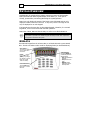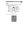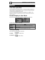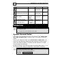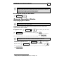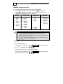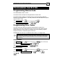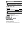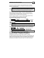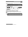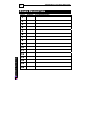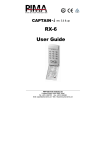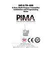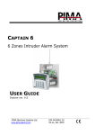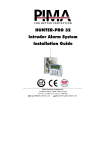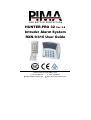
1
HUNTER-PRO 32 Ver. 3.8 Intruder Alarm System RXN-9/416 User Guide PIMA Electronic Systems Ltd. 5 Hatzoref Street, Holon 58856, Israel ℡ +972-3-5587722 +972-3-5500442 [email protected] http://www.pima-alarms.com 2 HUNTER-PRO 32 User Manual LED Keypads PIMA Electronic Systems Ltd. does not represent that its Product may not be compromised and/or circumvented, or that the Product will prevent any death, personal and/or bodily injury and/or damage to property resulting from burglary, robbery, fire or otherwise, or that the Product will in all cases provide adequate warning or protection. The User understands that a properly installed and maintained equipment may only reduce the risk of events such as burglary, robbery, and fire without warning, but it is not insurance or a guarantee that such will not occur or that there will be no death, personal damage and/or damage to property as a result. PIMA Electronic Systems Ltd. shall have no liability for any death, personal and/or bodily injury and/or damage to property or other loss whether direct, indirect, incidental, consequential or otherwise, based on a claim that the Product failed to function. Warning: The user should follow the installation and operation instructions and among other things test the Product and the whole system at least once a week. For various reasons, including, but not limited to, changes in environment conditions, electric or electronic disruptions and tampering, the Product may not perform as expected. The user is advised to take all necessary precautions for his/her safety and the protection of his/her property. This document may not be duplicated, circulated, altered, modified, translated, reduced to any form or otherwise changed; unless PIMA’s prior written consent is granted. All efforts have been made to ensure that the content of this manual is accurate. Pima retains the right to modify this manual or any part thereof, from time to time, without serving any prior notice of such modification. Please read this manual in its entirety before attempting to program or operate your system. Should you misunderstand any part of this manual, please contact the supplier or installer of this system. Copyright 2006 by PIMA Electronic Systems Ltd. All rights reserved. You can contact us at PIMA Electronic Systems Ltd.5 Hatzoref Street, Holon 58856, Israelhttp://www.pima-alarms.com SAFETY INSTRUCTIONS Your HUNTER-PRO 32 alarm system has been registered in accordance with EN60950 and its rules. EN 60950 requires us to advise you the following information: 1. In this alarm system exist hazards of fire and electric shock. To reduce the risk of fire or electric shock, do not expose this alarm system to rain or moisture. Pay attention: Telephone cords could be a good conductor for lightings energy. 2. Do not open the door of the alarm system. Dangerous high voltages are present inside of the enclosure. Refer servicing to qualified personnel only. 3. This alarm system should be used with AC 230V/110V, 50Hz, protected by anti electric shock breaker. To prevent electric shocks and fire hazards, do NOT use any other power source. 4. Do not spill liquid of any kind onto the unit. If liquid is accidentally spilled onto the unit, immediately consult a qualified service. 5. Install this product in a protected location where no one can trip over any line or power cord. Protect cords from damage or abrasion. 6. Disconnect all sources of power supply before proceeding with the installation. Pay attention: do not install low voltage wires near by AC power wires they should be separated. 7. Connect the AC transformer output to the terminal block on the control panel as marked. 8. Connect the AC line cord to line power terminals as marked. (GND; N; L) HUNTER-PRO 32 User Manual LED Keypads 3 INTRODUCTION Congratulations on your purchase of the HUNTER-PRO 32 Intruder Alarm System! Much care has been taken in developing the HUNTER-PRO 32 Intruder Alarm system, which will provide you with unprecedented peace of mind. The HUNTER-PRO 32 user-friendly operation and advanced features will professionally protect your home or business. HUNTER-PRO 32 Intruder Alarm System contains numerous features that allow it to befit the customer’s individual needs, and yet remain easy to program and use both by the customer and the technician. Therefore, it is important to read this manual from cover to cover in order to familiarize yourself with the system and take full advantage of its features. To assure optimal safety and security, you should test the HUNTER-PRO 32 Intruder Alarm System once a week. For any further questions, please do not hesitate to contact your local PIMA Distributor or PIMA directly at: PIMA Electronic Systems Ltd. Tel.: +972–3–558 7722 Fax: +972–3–550 0442 Email: [email protected] Up to date literature is available to download from our website: www.pima-alarms.com Main Features HUNTER-PRO 32 ! 9 zones in control panel. Expanded up to 32 zones ! Supports a wide range of partition options and independent subsystems ! Full supervised wireless devices ! Four Monitoring Stations phone numbers ! LCD keypad with Menu-Driven screens for easy programming and operation as well as two types of LED keypads ! Up to 24 users with various authorization levels ! Automatic Arming at a preset time and/or after a preset silence time (per partition) ! System remote control via any touchtone telephone ! Sirens monitored and reported for wires cut to CMS ! Various test options for zones and devices HUNTER-PRO 32 User Manual LED Keypads 4 KEYPAD OVERVIEW HUNTER-PRO 32 Intruder Alarm System supports two types of LED keypads: RXN-9 and RXN-416. Both keypads display zone status (i.e., zone open or closed), system faults, and arming/disarming the system/partition. RXN-9 can only display the status of the first 9 zones while RXN-416 can only display the status of the first 16 zones. In any case, zones 17 through 32 can only be displayed on an LCD keypad. The keypads use the same bus as other PIMA keypads. Therefore, if is set with keypad ID, it can be monitored and used with partitions. RXN-9 has 9 LEDs, RXN-416 has 16 LEDs, as well as more fault indications. NOTE: It is possible to purchase from PIMA a keypad with tamper switch that "supervises" the keypads connected to the system RXN-416 The RXN-416 keypad has 16 red zone LEDs, a red Fault LED and a green Armed LED. The 16 zone LEDs are also used for displaying faults (as described below). Zone Status: The status of each zone is listed above its number. Faults: Long press on the [NEXT] key changes LED display to system faults (see Faults Table for details). Fault Notification: The red FAULT LED blinks when a fault is detected. RXN-416 1 2 3 4 5 6 7 8 9 10 11 12 13 14 15 16 Armed Indicator: The green ARMED LED provides the system arm status as follows: OFF: System/partition is Disarmed. ON: System is in Arm mode. Blinking: System/ partition is in Entry or Exit Delay Mode. HUNTER-PRO 32 User Manual LED Keypads 5 RXN-9 The RXN-9 keypad has 9 red LEDs under the 9 keys (1-9). The LEDs give two types of indications: zone status and faults (as described below). A red Fault LED, a green Armed LED and a red Bypass LED. Fault Notification: The red FAULT LED blinks when a fault is detected. Armed Indicator: The green ARMED LED provides the system arm status as follows: OFF: System/partition is Disarmed. ON: System is in Arm mode. Blinking: System/partition is in Entry or Exit Delay Mode. Zone Status: The status of each zone is listed by its number. BACK Faults: Long press on the [INFO] key changes LED display to system faults (see Faults END Table for details). Bypass: The red BYPASS LED is ON when one (or more) zones is bypassed. NEXT ENTER INFO Lid Please note the different operation keys in both keypads: RXN-9 RXN-416 HUNTER-PRO 32 User Manual LED Keypads 6 DISPLAY First time operation When the keypad is connected to power, its circuitry and LEDs are tested. All LEDs will light in a changing pattern for 2-3 sec and then the keypad will start operating with the HUNTER-PRO 32 panel. Each LED corresponds with a different zone (numbers 1-9 – RXN-9 / 1-16 – RXN-416). The LEDs are OFF when the zones are closed and flash when the zones are open. Normal Display in User Mode Each LED corresponds a zone (numbers 1-9 – RXN-9 / 1-16 – RXN-416). Zone LED Display Status OFF Zone is closed Flashing Zone is open ON Zone caused an alarm Operation LEDs indication in User Mode: Operation LEDs Status Fault ON Fault with the system. Use the next section to display fault(s) Armed ON System is armed Bypass ON One zone or more have been bypassed in the system. Fault(s) Display When a fault occurs the red FAULT LED blinks. In RXN-416: In RXN-9: to display faults to display fault(s) HUNTER-PRO 32 User Manual LED Keypads 7 The corresponding fault LED will light as described in the following table: LED No. 1 2 Indication BATTERY AC * 3 PHONE 4 DC 5 * * * ZONE 6 CLOCK 7 TAMPER 8 FUSE * 9 BELL * 10 I/O-W * * I/O-8 12 KEYPAD Fault Description * Keypad Low battery RXN-9/416 No voltage from mains RXN-9/416 No communication with monitoring station or, a problem with telephone line RXN-9/416 Low voltage RXN-9/416 Fault zone RXN-9/416 Hour and/or date are not set RXN-9/416 Open tamper RXN-9/416 Detector’s voltage is short RXN-9/416 External/Internal Bell fault RXN-9/416 A problem with the wireless receiver * 11 * RXN-416 A problem with one of the remote expanders RXN-416 A problem with one of the system keypads RXN-416 * These faults should be fixed by a qualified technician/installer Programming/connection error: The keypad ID should be reprogrammed Numerical LEDs are flashing left-to-right RXN-9/416 Programming/connection error: The keypad is disconnected from the panel Numerical LEDs are flashing right-to-left RXN-9/416 User Menu Display Accessing User Menu – by entering Master Code, Enabled User Code, or long press and User Code (see System Access Codes on page 8) – turns ON the on ARMED and FAULT LEDs. Pressing a programming menu key (see below table) will turn ON the corresponding LED number (the key itself on the RXN-9 and the LED number in the keypads panel on the RXN-416). Key After entering Master/User Code (short press) Temporary bypass of zones Secondary Function (long press) - Programming telephone numbers - LED Indication Keypad Numerical LED 3 constantly ON RXN-9/416 Numerical LED 6 constantly ON RXN-9/416 HUNTER-PRO 32 User Manual LED Keypads 8 - Numerical LED 8 constantly ON RXN-9/416 - Numerical LED 9 constantly ON RXN-9/416 Numerical LED 7 constantly ON RXN-9/416 Numerical LED 4 constantly ON RXN-9/416 Programming time and date (After pressing NEXT) Programming the user codes Programming zones for Chime feature Programming automatic arming hour and silent time for automatic arming Enabling/Disa bling the Chime feature And valid User Code brings User Menu OPERATION NOTE: Regular key press Long key press, until confirmation beep is heard System Access Codes The system can be operated using each of the following codes: Master Code, User Code, and Short Code. The Short Code is only useful for arming the system. There are two additional unique codes, Duress Code and Relay Code. The Duress Code will disarm the system and at the same time will send a duress event to the monitoring station. The Relay Code will activate the on board relay according to programming. By default, entering a User Code will toggle the partition/system state (i.e., if it was disarmed it will commence arming and if it was armed it will disarm). NOTES: The system’s default Master Code is: 5555 The User Menu can also be accessed as follows: User Code or Installer Code HUNTER-PRO 32 User Manual LED Keypads 9 It is possible (programmable only by the installer) to enable a User Code entering the User Menu instead. When this option is enabled, the user code is referred to as Enabled User Code. Enabled User Code will function as the Master Code with the limitation of NEVER being able to set the Master Code and it can only access enabled functions (programmable). Signals during Arming Arming with closed zones (normal) Before arming the system, make sure all zones are closed (except Exit Delay zones – usually zones on exit route). Make sure that all zone LEDs are OFF. After entering one of these codes, the green 'Armed' LED will flash and a constant beep (once per second) will be heard from the keypad during the exit delay period. At the end of the exit delay, the green control LED shall stop to blink and turn ON and the beep will stop. Arming with Open Zones When activating the system with one or more opened zones (that are not Exit Delay zones), the keypad will beep fast (two beeps per second). With RXN-9 the bypass LED (right red LED) will blink. At this stage, there are two options to continue: Bypass open zones: The system is armed and open zones are system does not arm and returns to bypassed until system is disarmed Cancel arming: normal operating mode Arming the System Arming with Master Code Full arming with User Code, Enabled User Code or Short Code Master Code Short Code OR User Code HUNTER-PRO 32 User Manual LED Keypads 10 Entering the User or Short codes will arm the system immediately! OR Enabled User Code Arming the system to HOME Mode Arming “HOME 2”: Arming “HOME 1”: Short Code or User Code or Enabled User Code Short Code or User Code or Enabled User Code Fast Arming (without code) For quickly arming the system (possible only if enabled by installer): Full Arming: Arming HOME 1: Arming HOME 2: NOTE: Exit Delay in HOME 1 and HOME 2 can be disabled by the installer. Entering the User Menu From this point forward, every time Master Code is mentioned in operation and/or programming, the explanation is the same for Enabled User Code and for User Code or Installer Code that accesses the User Menu by long press ( of the ) key before entering the code. All these will access the User Menu. On RXN-9, the middle green LED and the left red LED turn ON. On RXN-416, the green Arm and the red Fault LEDs turn ON. The system awaits user selection. Disarming the System Disarming the system with User Code User Code HUNTER-PRO 32 User Manual LED Keypads 11 NOTES: If the system does not turn to Disarm state, check the time frame for disarming the system (see section “Programming User Codes”). A User Code can ONLY disarm its allocated partition. Disarming the system via User Menu Master Code General Operation Modes Displaying Bypassed Zones NOTE: RXN-416 does not have a bypass LED. Display: If the bypass LED (RXN-9 only) is ON, there is one or more userbypassed zones in the system. To Bypass a zone: Zone number ( Master Code the pressed zone LED starts blinking 1) (LED 3 constantly ON, LED 1 blinks) (the pressed zone LED stops blinking and the next sequential zone starts blinking) NOTE: When Bypass mode is executed, it is effective until system is disarmed. To Rearm a bypassed zone: ON, LED 1 blinks) Master Code Zone number ( (LED 3 constantly the pressed zone LED starts blinking1 ) (the pressed zone LED stops blinking and the next sequential zone starts blinking) 1 If key (zone) 3 is pressed, the LED stays constantly ON HUNTER-PRO 32 User Manual LED Keypads 12 Chime Mode Enable : (enable all programmed chime zones) NOTE: This mode activates a buzzer in the keypad when a chime zone is triggered. This feature can be used to monitor unauthorized entry or exit in the defined zone when the system is not armed. Disable: (disable all programmed chime zones) Initiate Responses PANIC: and simultaneously for two seconds. NOTE: You can customize your system's response to a panic event, for example, calling the Monitoring Station or your private telephone number. Consult your installer about programming a Panic Response. Keypad Audible Tones Disable: and simultaneously. NOTE: When the keypad's Audible Tone feature is disabled, all audible tones and indications, with that keypad, are silenced. Enable: and simultaneously until you hear a beep. Arming/Disarming with a Key HUNTER-PRO 32 can be armed/disarmed with a key. Turn to the installer in order to use this feature. NOTE: It is possible for the installer to program the system to produce a short beep when the system is armed/disarmed with the key. HUNTER-PRO 32 User Manual LED Keypads 13 Remote Control via Touch-tone Phone The alarm system can be remote-controlled via any touch-tone telephone, including cellular phone. The system can be controlled from the moment communication is established, whether the system called the telephone, or when initiated by the user as following described. 1. Dial the telephone number that the system is connected to 2. Wait for the system’s confirmation tone (a long tone followed by two beeps) 3. Enter the Master Code (note NOT to enter the code before the end of the confirmation tone) 4. Wait a few seconds until the alarm system confirms its status, using one of the two following tones: Continuous tone: System is disarmed Beeping sound: System is armed NOTES: The system will not identify commands from the telephone while sounding the confirmation tone. It is important to wait until the confirmation tone is finished before pressing the telephone keys that control the system. The alarm system confirms the command was received by two short beeps. There are two modes for controlling the system, as set by the installer: MODE A - One touch control 5. Execute command by single key pressing on the phone. The following table includes system’s commands by phone keys: Phone key: 1 2 4 5 6 7 8 0 Function: Arm the system Disarm the system Arm the system in “Home 1” mode Switch on the Relay Switch off the Relay Arm the system in “Home 2” mode Listen in (only available with a MIC-200 installed) Disables siren and dialer (in case of an alarm) HUNTER-PRO 32 User Manual LED Keypads 14 MODE B - Enhanced control The enhanced mode enables full control of all systems outputs. 6. Execute command by pressing keys combination: to activate an output; to deactivate an output. The command is followed by the output code as described in the following table. N K General 00 - Disable dialer *01 - Arm #01 - Disarm 04 - Home 1 07 - Home 2 08 - Listen-in Control panel 11 - Siren 1 12 - Siren 2 13 - Relay 14 - SMOKE detector 15 - ON/OFF output 16 - ALARM output Output card 21 - Output no.1 22 - Output no.2 . . . . 28 - Output no.8 Expanders 31 - Expander no.1 relay 32 - Expander no.2 relay 33 - Expander no.3 relay NOTES During communication time between system and telephone, the following display will appear on the keypad: Other keypad in use If the system receives no command within a minute, it will disconnect from the line and return to normal operation. Each time an additional minute of listening (listen-in function) is required, the N 0 8 keys should be pressed again. Examples: To disarm the system: Dial and wait for confirmation tone tone Master Code (on telephone keys) K 0 1 wait for confirmation To activate output No.5 on output card OUT-1000: Dial and wait for confirmation tone tone Master Code (on telephone keys) N 2 5 wait for confirmation HUNTER-PRO 32 User Manual LED Keypads 15 PROGRAMMING THE SYSTEM Programming Master Code The default Master Code is: 5555. The Master Code can ONLY be changed with the master code. The Master Code is used for accessing memory and programming different functions as described further. It is also possible to arm and disarm the system with the Master Code. Master Code New Master Code (4-6 digits) (LED 9 constantly ON) X3 Programming User Codes The User Codes are mainly for arming and disarming the system, but depending on the user’s authorization level, the user can also enter the User Menu and perform various tasks as changing other users settings, program telephone numbers, temporarily bypass zones etc. HUNTER-PRO 32 holds up to 24 different User Codes, 4 to 6 digits each. NOTE: An LCD keypad is required to program user names, a time frame in which he/she will be able to disarm the system, allocated to one or more partitions and specific authorizations. Adding a User Master Code User number to program X 2 X3 New User Code (4-6 digits) (LED 9 constantly ON) (LED 9 constantly ON, LED 1 blinks) Deleting a User Master Code User number to program X 2 (LED 9 constantly ON) LED 1 blinks) X3 (LED 9 constantly ON, HUNTER-PRO 32 User Manual LED Keypads 16 NOTE: With RXN-9, when selecting users 1 through 8, the corresponding number (key) will blink. With RXN-416, when selecting users 1 through 8 and 10 through 16 the corresponding zone LED will blink. Setting Time and Date Time and date should be accurate because they are used in the system's memory log, Automatic Arming, and reporting to monitoring station. To set time and date: Master Code TIME (HH:MM) DATE (DD/MM/YY) (LED 8 constantly ON, LED 1 blinks) (LED 8 constantly ON, LED 2 blinks) NOTE: Enter time in 24:00 (HH:MM) format and date in day/month/year format The system will not accept meaningless data, such as 25:25 time. Example: To program 6:35 PM @ October 21st, 2005 do: Master Code (LED 8 constantly ON, LED 1 blinks) (LED 8 constantly ON, LED 2 blinks) Automatic Arming The system can be automatically armed with one of the following three options: 1. At a preset time; 2. After silence-time period; 3. Silence time can be programmed per partition (by technician) At the preset time or after silence-time period, the system will commence autoarming unless it was armed before that time. This feature is valid for all weekdays. HUNTER-PRO 32 User Manual LED Keypads 17 The system can detect movement in the protected area via its connected detectors and sensors, therefore, it can identify no-movement hence there is no one in the protected area. NOTE: The silence (no movement) timer will start counting down ONLY if no immediate zones are opened and after the last zone to be closed is the exit delay zone (i.e. the exit door). Any immediate zone opening will terminate the countdown. When the system starts auto-arming, a 45 seconds ‘warning countdown’ will start, indicating the arming countdown is to follow. Note that during the ‘warning countdown’ the keypad will beep. During the ‘warning countdown’, any disarming code can cancel the auto-arming process. After the ‘warning countdown’ is over, the system will begin regular arming process, including exit delay and beeps from the keypad. Programming Auto-Arming at Preset Time Master Code Time in which the system will be armed (HH:MM) (LED 4 constantly ON) (LED 4 constantly ON, LED 1 blinks) NOTE: To cancel Auto-Arming, the Automatic Arming programming needs to be repeated, and the time to be set as 00:00. Programming Auto-Arming after Silence-Time is Terminated Master Code Silence Time in minutes (250 minutes max) (LED 4 constantly ON, LED 2 blinks) NOTE: An LCD keypad is required to program silent time per partition. Private Dialer Telephone Numbers HUNTER-PRO 32 system has four private dialer telephone numbers. The dialer will dial each phone number in two sets (i.e. total of 8 attempts) and trigger an alarm warning sound, when the call is ‘picked-up’. After the warning sound is over, the system awaits for remote-controlled commands that can be transmitted via the telephone used by the system. The system will hang-up HUNTER-PRO 32 User Manual LED Keypads 18 after a minute of not receiving any command (Remote Control via Touch-tone Phone on page 13). NOTE: In case a Voice-Unit with a recorded message is connected to the system, once the call is picked-up, the system will play the recorded message and not a warning sound. The dialer aborts the dialing attempts in the following cases: ! The system’s status changes from ON to OFF ! A “Stop Dialer” command was received via telephone. The first Private Dialer User that gives an ‘abort’ command causes the other Private Dialer Users in the phone list to stop receiving the system’s report. ! All Private Dialer Telephone Numbers have been dialed twice Programming Telephone Numbers It is possible to combine the process of entering/deleting/changing programmed telephone numbers once in the Telephone Menu. Master Code number no. 1 no. 2 no.3 no.4 to exit. (LED 6 constantly ON, LED 1 blinks) (LED 6 constantly ON, LED 2 blinks) Telephone Telephone number (LED 6 constantly ON, LED 3 blinks) Telephone number (LED 6 constantly ON, LED 4 blinks) Telephone number Deleting a Programmed Telephone Number To delete a programmed telephone number, press the key instead of the telephone number. Chime Programming the “Chime” feature enables to control opening/closing doors and windows by activating the keypad’s buzzer for two seconds each time a HUNTER-PRO 32 User Manual LED Keypads 19 door/window is opened. This feature is especially useful when there are small children in the house, or in shops. NOTE: The “Chime” feature is only enabled when system is disarmed. Programming Chime Zone Master Code (LED 7 constantly ON, LED 1 blinks) (the pressed zone LED starts blinking2) to confirm or Zone number to release to exit. For temporary cancellation of Chime see Chime Mode on page 12 Smoke and Fire Detectors Alarm In case an alarm is triggered due to smoke/fire detectors, press and hold the key (until a confirmation sound is heard) in order to reset and release the detector. NOTE: The smoke detector returns to normal operation mode after the smoke timer is finished. 2 If key (zone) 7 is pressed, the LED stays constantly ON HUNTER-PRO 32 User Manual LED Keypads 20 ZONES DESCRIPTION Zone # P/N 4410212 Rev. D (July-2006) 1 2 3 4 5 6 7 8 9 10 11 12 13 14 15 16 Partition # Zone Name/Description