1
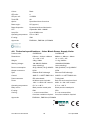
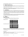
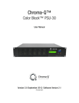
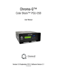
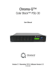
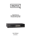
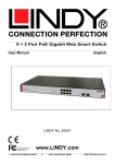
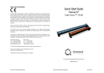
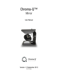
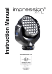
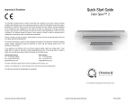
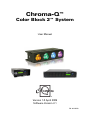
Chroma-Q™
Color Block 2™ System
User Manual
Version 1.0 April 2009
Software Version 2.1
PN: 603-0500
Disclaimer
The information contained herein is offered in good faith and is believed to be accurate.
However, because conditions and methods of use of our products are beyond our control, this
information should not be used in substitution for customer's tests to ensure that Chroma-Q
products are safe, effective, and fully satisfactory for the intended end use. Suggestions of use
shall not be taken as inducements to infringe any patent. Chroma-Q sole warranty is that the
product will meet the sales specifications in effect at the time of shipment. Your exclusive
remedy for breach of such warranty is limited to refund of purchase price or replacement of any
product shown to be other than as warranted.
Chroma-Q reserves the right to change or make alteration to devices and their functionality
without notice due to our on going research and development.
The Chroma-Q Color Block 2 System has been designed specifically for the lighting industry.
Regular maintenance should be performed to ensure that the products perform well in the
entertainment environment.
If you experience any difficulties with any Chroma-Q products please contact your selling
dealer. If your selling dealer is unable to help please contact [email protected]. If the
selling dealer is unable to satisfy your servicing needs, please contact the following, for full
factory service:
Outside North America:
Tel: +44 (0)1494 446000
Fax: +44 (0)1494 461024
[email protected]
North America:
Tel: 416-255-9494
Fax: 416-255-3514
[email protected]
For further information please visit the Chroma-Q website at www.chroma-q.com.
Chroma-Q is a trademark, for more information on this visit www.chroma-q.com/trademarks.
The rights and ownership of all trademarks are recognised.
Color Block 2 User Manual
1
V1.0 April 2009
Table of Contents
1.
2.
3.
4.
5.
6.
7.
8.
9.
Product overview..................................................................................................3
1.1
Chroma-Q Color Block 2 …………………………………………………….. 3
1.2
Chroma-Q Color Block Power Supply Units ……………………………… 3
Operation...............................................................................................................4
2.1
Unpacking the units ………………………………………………………….. 4
2.2
Cabling …………………………………………………………………………. 4
2.3
Fixings ………………………………………………………………………….. 7
2.4
Control …………………………………………………………………………. 9
Troubleshooting..................................................................................................19
Specification........................................................................................................19
4.1
Technical specifications – Color Block 2 ………………………………… 19
4.2
Technical specifications – Color Block Power Supply Units …………. 20
4.3
Photometric Performance …………………………………………………. 21
4.4
Drawings ……………………………………………………………………… 21
Maintenance........................................................................................................22
Battery Replacement ..........................................................................................23
Installation...........................................................................................................23
Wiring...................................................................................................................23
Accessories..........................................................................................................24
Color Block 2 User Manual
2
V1.0 April 2009
1.
Product overview
1.1 Chroma-Q Color Block 2
Following the enormous success of the Chroma-Q Color Block™ LED fixture with rental
companies and end users alike, the manufacturer has combined the product's core elements of
modularity and versatility with new single color RGBA optics, 530 lumens output (almost double
the original model) and theatrical grade dimming to create the exceptional feature set of the
Color Block 2 fixture.
With its radically increased color palette and high CRI of 90, the Color Block 2 fixture is a master
at creating vibrant bold colors and subtle theatrical hues. Combined with its built-in variable
color temperature capability, even flesh tones look natural, satisfying all but the most critical
eye.
The four large, camera-friendly LED cells offer performers less glare and mix beautifully for
single color output, virtually eliminating the frustrating color separation shadows normally
synonymous with LED lighting. The beam optics have a soft asymmetrical quality carefully
crafted to give an immediate perfect color blend for uplighting surfaces, yet retain a soft
Fresnel-like edge for direct illumination. At close to twice the output of its predecessor, the
Color Block 2 fixture is bright enough to uplight a 6m / 20 feet set and then some.
Each Color Block 2 fixture features 48 high output LED set into 12 single optic RGBA clusters
that are grouped into 4 cells which produce an intense, powerful light and vibrant colours
across the spectrum.
The control options incorporate a choice of HSI (Hue, Saturation and Intensity), RGBA (Red,
Green, Blue, Amber), RGB(A) (Red, Green, Blue, with *Magic Amber), RGBI (Red, Green, Blue
with *Magic Amber and Intensity) control modes, and a dynamic Variable Effects Engine
integrated in the software which gives the lighting designer full control over colour and effects
combinations.
The product's lightweight yet robust, heavy gauge aluminium extruded construction houses a
discreet cable management system and additional protection is built around the LED lenses for
a truly road proof fixture.
A range of DMX controlled power supplies are available to accommodate most applications.
Each Color Block Power Supply features XLR4 outputs with a maximum capacity of 5 Color
Block 2 fixtures daisy chained together. See separate PSU user manual for control details.
* Magic Amber is the term used for the unit's ability to bring in Amber when mixing colours that require it
1.2 Chroma-Q Color Block Power Supply Units
Two DMX controlled power supply models are available to accommodate most applications or
operate independently as a stand alone system. Each Color Block Power Supply features
outputs via XLR4. The unit can be controlled remotely via ANSI E1.11 USITT DMX 512-A (XLR-5
pin).
Color Block 2 User Manual
3
V1.0 April 2009
Color Block PSU-05B
The Color Block PSU-05B is a power supply suitable for up to 5 Color Block DB4 LED fixtures or
5 Color Block 2 LED fixtures. It can be controlled remotely via ANSI E1.11 DMX 512-A in a
variety of modes to accommodate most applications or can operate independently as a standalone system.
The Color Block PSU-05B delivers power and data via 1 XLR4 output. A maximum of five daisychained Color Block 2 fixtures can be connected to the PSU-05B. Return lines are not required.
The total cable length of each chain must not exceed 60m/200ft. Two in/out ethernet RJ45
connectors are available for synchronisation.
Color Block PSU-30
The Color Block PSU-30 is a 2U 19” rack mounted power supply suitable for up to 30 Color
Block DB4 LED Fixtures or 30 Color Block 2 LED Fixtures. It can be controlled remotely via ANSI
E1.11 USITT DMX 512-A in a variety of modes to accommodate most applications or can
operate independently as a stand-alone system.
The Color Block PSU-30 delivers power and data via 6 XLR4 outputs. A maximum of five daisychained Color Block 2 fixtures can be connected to each XLR4 output. Return lines are not
required. The total cable length of each chain must not exceed 60m/200ft. Two in/out Ethernet
RJ45 connectors are available for synchronisation.
2.
Operation
2.1 Unpacking the units
The Color Block 2 package includes 1 unit Color Block 2 fixture and a Quick Start Guide. We
recommend that you keep the original packaging in case item needs to be returned.
The Color Block PSU-05B package includes 1 unit PSU-05B, IEC power cord and a Quick Start
Guide. The Color Block PSU-30 package includes 1 unit PSU-30 and a Quick Start Guide.
2.2 Cabling
DMX Input control data from an external control console is through an XLR 5-pin cable:
Pin#
1
2
3
4
5
Color Block 2 User Manual
Function
Ground (Screen)
Data Minus
Data Plus
Spare Data Minus
Spare Data Plus
4
V1.0 April 2009
Power and control data outputs from the Color Block power supply to the fixture is through an
XLR 4-pin cable. The drain wire should be connected to the chassis of the XLR.
Pin #
1
2
3
4
Chassis
Function
Ground (-ve)
Control data minus (-)
Control data plus (+)
24V DC (+ve)
Cable shield/drain wire
Minimum Cable size
2.50mm² (14 AWG)
0.35mm² (22 AWG)
0.35mm² (22AWG)
2.50mm² (14 AWG)
0.25mm² (24 AWG)
Only genuine Tourflex Datasafe cable is recommended for use with the Color Block 2 system.
Damage will occur if power connections short-circuit to data or ground shield connections.
When assembling XLR4-pin cables, heat shrink should be used on each individual data pin and
the drain wire to prevent short circuits.
The Color Block PSU-05B delivers power and data via 1 XLR4 output. A maximum of five daisychained Color Block 2 fixtures can be connected to the PSU-05B. Return lines are not required.
The total cable length of each chain must not exceed 60m/200ft.
It is recommended that a maximum of 20m XLR4 cable length should separate adjacent fixture
units as to avoid signal deterioration.
Note: Maximum of 5 Color Block 2 fixtures per cable. No return cables required.
The Color Block PSU-30 delivers power and data via 6 XLR4 outputs. A maximum of five daisychained Color Block 2 fixtures can be connected to each XLR4 output. Return lines are not
required. The total cable length of each chain must not exceed 60m/200ft.
It is recommended that a maximum of 20m XLR4 cable length should separate adjacent fixture
units to avoid signal deterioration.
Note: Due to the higher levels of leakage current of the PSU-30 it is important that the XLR4
cables used are manufactured only to the specification detailed above. It is also important that
the cables are not coupled or uncoupled whilst the PSU is powered and that the PSU is
correctly grounded.
Color Block 2 User Manual
5
V1.0 April 2009
Color Block 2 User Manual
6
V1.0 April 2009
2.3 Fixings
One of the strengths of the Color Block 2 fixture is its flexible fixing possibilities. The Color Block
2 fixture is supplied with an integral M10 clinch nuts at each end. These can be used to attach
the Color Block 2 fixture to a standard hook clamp or the wide range of Color Block accessories
listed below.
Note: Damage may occur if the bolt is too long (M10x16 maximum). In addition, both sides of
the fixture feature a fixing slot designed to accept an M6 bold head.
The Color Block 2 fixture also features an integral connection system to enable up to five units
to be locked together as a batten (see below).
Note: it is important to ensure that each fixture is also secured with a safety bond. The end
plate of each fixture has a fixing hold to facilitate secondary fixings.
a. Integrated connection system
One end of the Color Block 2 fixture features two protruding locating pins and a catch plate, the
other end has two keyhole slots and a butterfly latch.
1. To connect two fixtures together, firstly mate the two protruding pins from one fixture into
the keyhole slots of the other.
2. Then slide the fixtures together so that they are aligned correctly, taking care to get past the
extended catch plate.
Note: This will be stiff on new fixtures and a twisting action may ease assembly.
3. Finally use the butterfly latch to secure the fixtures together tightly (max 5 units together).
Note: It is important to ensure adequate ventilation to the rear of all Color Block fixtures. Never
place the fixtures directly on the floor pointing upwards when configured as a batten.
Color Block 2 User Manual
7
V1.0 April 2009
The Color Block 2 fixture is supplied with an integral M10
clinch nuts at each end. These can be used to attach the
Color Block 2 fixture to a standard hook clamp.
Note: damage may occur if the bolt is too long. (M10x16
maximum)
b. Batten bracket kit for up to five fixtures
The batten bracket set is supplied as a pair of brackets with fibre washers and thumb wheels.
The batten bracket set can be used for floor mounting (see photo), direct wall mounting and
truss mounting when used in conjunction with hook clamps or half couplers.
c. Yoke kit for single fixture
The yoke kit for single fixture is supplied as a yoke bracket with fibre washers and thumb
wheels.
The yoke kit can be used for floor mounting (see photo), direct wall mounting and truss
mounting when used in conjunction with hook clamps or half couplers.
d. Dual mode yoke kit for single fixture
The dual mode yoke kit for single fixture is supplied with fibre washers and thumb wheels. The
dual mode yoke combines the function of the single yoke and the batten bracket.
e. Blinder frame for four fixtures
The blinder frame is supplied as a yoke bracket, side plates, fibre washers, thumb wheels and
eight M10 bolts.
The blinder frame is designed to truss mount with the use of a half coupler.
The end plates feature two complete sets of fixture fixing holes. Set one hold the fixtures
closely together ensuring equal centres for all sixteen cells. Sets two are adjustable and allow
the Color Block 2 fixtures to be splayed out at varying angles.
Color Block 2 User Manual
8
V1.0 April 2009
f. Hinge kit
The hinge kit is supplied as one complete hinge with fibre washers and M10 bolts.
The hinge kit fits between two Color Block 2 fixtures and offers an angle adjustment of 180 deg.
If used in multiples, unique shapes can be achieved, such as hexagons, octagons etc.
g. Wall bracket for single fixture
The Wall bracket for single fixture is a discreet fixing suitable for fixing a single Color Block 2 to
a wall or set piece. Keyhole slots are provided to for vertical or horizontal fixing.
2.4 Control
The Chroma-Q Color Block 2 is controlled via two models of addressable ANSI E1.11 USITT
DMX512-A power supply units, the 5 way Color Block PSU-05B and the 30 way Color Block
PSU-30.
The Color Block PSU-05B and PSU-30 menu items are accessed via the LCD display and the
following controls:
• Right hand button (red) = Enter (hold for 2 seconds to save)
• Left hand button (blue) = Exit without saving
• Wheel = Adjusts values or scrolls through menu items
The LCD screens shown above are currently at the Home position and display: product name
and model, software version, current DMX address, current control mode and time.
If left unadjusted at a main menu position for 5 second the LCD screen will revert to the Home
position.
a. Control Options
3 channel HSI (Hue, Saturation and Intensity) gives 2 colour channels for hue and saturation and
a separate intensity channel. A separate definable intensity channel is particularly useful when
Color Block 2 User Manual
9
V1.0 April 2009
creating intensity chases or when the grand master is used. The hue channel has 255 different
colours available and the saturation channel specifies the saturation level of that colour. The
saturation channel is fully saturated at full. White is achieved with the intensity channel to full
and the saturation channel at zero.
3 channel RGB (Red, Green, Blue with *Magic Amber) is the more traditional way of controlling
colour changing LED fixtures. Each of the three control channels directly affects the intensity of
the corresponding LED. Colour is mixed by adjusting the levels of the three primary colours.
White is achieved with all channels at full including *Magic Amber.
3 channel RGB(A) + 1 intensity channel (Red, Green, Blue with *Magic Amber and Intensity)
gives 3 control channels directly affecting the intensity of the corresponding LED – Red, Green,
Blue with *Magic Amber, and 1 channel affecting the intensity of all RGB(A) channels.
4 channel RGBA (Red, Green, Blue and Amber) gives 4 control channels directly affecting the
intensity of the corresponding LED – Red, Green, Blue and Amber. Color is mixed by adjusting
the levels of each of the four colors. White is achieved with all channels at full.
Grouping options: grouping by individual “cell”, grouping by “block” and “all”. A Color Block 2
fixture consists of 4 cells. “Cell” grouping allows individual control of each single cell. In “Block”
grouping, the 4 cells in each Color Block 2 fixture are grouped and controlled as 1 block. In “All”
grouping, all fixtures connected to a power supply can be controlled as 1 group.
Internal FX engine: modes 1, 4, and 7 incorporate a comprehensive internal FX engine with
seven variable parameters to create an unlimited amount of unique lighting effects.
* Magic Amber is the term used for the unit's ability to bring in Amber when mixing colors that require it.
b. Control Menu
Use the wheel to scroll through the control menu positions:
Home / DMX Address
To set the DMX start address of the PSU-05B/PSU-30, press Enter, scroll wheel to
adjust DMX start address, press Enter for 2 seconds to save settings.
Control Mode
The PSU-05B/PSU-30 can be set to operate in 16 DMX controlled modes for the
Color Block 2 system (CB2). Go to “System” and select “CB2”. 3 grouping options
are available (cell-grouped, block-grouped, all-grouped) with 5 control options:
HSIFX, HSI, RGB (with *Magic Amber), RGBA, RGBI (with *Magic Amber), preprogrammed looks and stand alone effects. Refer to the list below for details. Press
Enter, scroll wheel to select control mode, and press Enter for 2 seconds to save
control mode settings.
Mode
Group
Ch
1
2
3
4
5
6
7
8
9
10
11
12
13
14
15
16
Variable
Cell
Cell
Block
Block
Block
All
All
All
Cell
Cell
Block
Block
All
All
Any
67
60
60
21
15
15
9
3
3
80
80
20
20
4
4
1
Color Block 2 User Manual
PSU-05B
System: CB2
7FX + 20 x HSI
20 x HSI
20 x RGB (with *Magic Amber)
6FX + 5 x HSI
5 x HSI
5 x RGB (with *Magic Amber)
6FX + HSI
1 x HSI
1 x RGB (with *Magic Amber)
20 x RGBA
20 x RGBI (with *Magic Amber)
5 x RGBA
5 x RGBI (with *Magic Amber)
RGBA
RGBI (with *Magic Amber)
Look Select
10
Ch
367
360
360
96
90
90
9
3
3
480
480
120
120
4
4
1
PSU-30
System: CB2
7FX + 120 x HSI
120 x HSI
120 x RGB (with *Magic Amber)
6FX + 30 x HSI
30 x HSI
30 x RGB (with *Magic Amber)
6FX + HSI
HSI
RGB (with *Magic Amber)
120 x RGBA
120 x RGBI (with *Magic Amber)
30 x RGBA
30 x RGBI (with *Magic Amber)
RGBA
RGBI (with *Magic Amber)
Look Select
V1.0 April 2009
When DMX is Lost
If DMX is not detected various output options can be selected: Press Enter, scroll
wheel to selection, press Enter for 2 seconds to save settings.
Off - will snap to off
Hold - will hold the last valid DMX state
Trig - will default to Time Trigger operation
Look 1-31 will snap to the Look of your choice
Look Store
The PSU-05B/PSU-30 has 31 internal preset FX Looks for stand alone operation, 1-23
are pre-programmed. To replay a Look in stand alone operation, scroll to Look Store,
press Enter, scroll and select the desired Look and press Enter for 2 seconds to save
settings. To replay a Look with a DMX console, scroll to Control Mode 16 and press
Enter for 2 seconds. Use the DMX console with the assigned channel to playback the
various looks stored. (1-31 looks in 1 single channel)
Note: DMX has priority over internal Looks.
Looks can be recorded to the internal flash memory by users and will be preserved
on power down. However, looks will be returned to default setting if menu 8 Reset is
performed. There are two ways to record a look:
Simple, with DMX console.
Set the PSU-05B/PSU-30 to the desired Control Mode. Use a DMX console to adjust
channel levels and create the desired look or effect. Scroll to Look Store and press
Enter, scroll to desired Look number and press Enter. Press Enter again for 2
seconds to save Look.
Advanced, stand alone. (DMX is unplugged)
Scroll to Look Store and press Enter, scroll to desired Look and press Enter to access
the memory data. The data is presented as two numbers separated by a letter “c”.
The number to the left of the c is the channel number and to the right is the channel
level. Scrolling to the far end of the wheel will show the Mode at which the selected
Look was programmed.
To edit the Mode of a selected Look:
Scroll to Look Store and press Enter, scroll to desired Look and press Enter to access
the memory data. Scroll the wheel to the far end until Mode number is shown and
press Enter. Scroll wheel to adjust the Mode number. Press Enter to toggle back to
the channel numbers.
To edit the channel numbers and levels of a selected Look:
Scroll to Look Store and press Enter, scroll to desired Look and press Enter to access
the memory data. Scroll the wheel to select the channel number. To edit the channel
level, press Enter and use the scroll wheel to adjust the level (shown as 0-255). Press
Enter to toggle back to the channel number. When the desired effect is created press
Enter for 2 seconds to save Look.
Time Triggers
The PSU-05B/PSU-30 has real time triggering of the internal Looks. Press Enter and
scroll to desired Time Trigger and press Enter. Press Enter to toggle between Day,
Hour (24), Minutes and Look to be triggered, adjusting the setting with the scroll
wheel as desired. Press Enter for 2 seconds to save settings. By default Time
Triggers will occur on all 7 days unless specified. The triggers will only be activated
when the feature “When DMX is Lost” is set to Trig.
Set Day and Time
Press Enter to toggle between Day, Hour (24) and Minutes, adjusting the setting with
the scroll wheel as desired. When the Day and Time is set correctly press Enter for 2
seconds to save settings.
Display Backlight (Displ. Backlight)
The LED display can be set to go off after 5 seconds of no activity. Press Enter, scroll
Color Block 2 User Manual
11
V1.0 April 2009
wheel to On (permanently) or Off (after 5 seconds) and press Enter for 2 seconds to
save settings.
Reset to Default
Press Enter for 2 seconds to reset all menu items to factory defaults:
DMX address = 001, Control Mode = 1 (67 or 367 channels HSI+FX) , DMX Lost =
Hold, Looks = default, Display = On, Frequency = 360, System = CB2
System
The PSU-05B/PSU-30 can be set to operate for the Color Block DB4 system (CB1) and
the Color Block 2 system (CB2). Press Enter, scroll wheel to select CB1 or CB2, press
Enter for 2 seconds to save settings.
Frequency
The PSU-05B/PSU-30 has four frequency settings available - 360, 600, 1200, 2400.
This allows for the LED scan rate to be synchronised with the video camera and
avoid a flickering effect. Press Enter, scroll wheel to select frequency, press Enter for
2 seconds to save settings.
Sync Mode
In normal operation internally generated FX should stay synchronised between the
PSU-05B’s/PSU-30’s for approx 30 minutes. If better synchronisation is required a
timing signal can be run via a RJ45 patch (not crossover) cable between PSU’s. In
order for this to work correctly one PSU-05B or PSU-30 must be designated as the
Master and all the others must be set to Slave.
Press Enter and use the scroll wheel to select Master or Slave. Press Enter for 2
seconds to save setting.
c. PSU-05B DMX Personality Mode 1-3
PSU-05B
(v2.1)
In mode 1 grouping is variable & in modes 2 -3 each cell is a group
Mode 1 (67ch) 7FX + 20 x HSI
Mode 2 (60ch)
Mode 3 (60ch)
20 x HSI
20 x RGB
(with *Magic Amber)
Channel 1
Channel 2
Channel 3
Channel 4
Channel 5
Channel 6
Grouping
0-100 Variable grouping range between 1-20
cells with FX running within the group.
102-206 variable grouping range between 1-20
cells with FX running between the groups.
209-255 Variable grouping range for every 2nd
to every 20th cells in a group.
Colour Speed
0-255 Variable speed of colour scrolling. From
static at 0 to maximum at 255.
Colour Fan
0-255 Variable fan of colour between / within
groups. All units are the same colour at 0.
Colour Range
0 Full spectrum
1-255 Variable limit of spectrum for colour
scrolling. Single colour at 1, full spectrum at
255.
Colour Step
0-255 Variable control of smoothness of colour
scrolling. Smoothest is at 0. Most coarse is at
250. Rate will vary with scrolling speed. 255
will override effects and switch to RGB.
Intensity Effects
0 Static
1-63 Fade on, fade off. Variable range, 63 the
fastest
64-127 Fade on, snap off. Variable range, 127
the fastest
Color Block 2 User Manual
12
Hue group 1
Red group 1
Saturation group 1
Green group 1
Intensity group 1
Blue group 1
Hue group 2
Red group 2
Saturation group 2
Green group 2
Intensity group 2
Blue group 2
V1.0 April 2009
Channel 7
Channel 8
Channel 9
Channel 10
Channel 11
Channel 12
Channel 13
Total
128-191 Snap on, fade off. Variable range, 191
the fastest.
192-255 Snap on, snap off (strobe). Variable
range, 255 the fastest.
Intensity Fan
Hue group 3
0-255 Variable fan of intensity effect between /
within groups. All units at the same intensity at
0. Alternating units on and off at 255.
Hue for group 1
Saturation group 3
Saturation for group 1
Intensity group 3
Intensity for group 1
Hue group 4
Hue for group 2
Saturation group 4
Saturation for group 2
Intensity group 4
Intensity for group 2
Hue group 5
...and so on up to group 20
67 DMX channels
60 DMX channels
Red group 3
Green group 3
Blue group 3
Red group 4
Green group 4
Blue group 4
Red group 5
60 DMX channels
d. PSU-05B DMX Personality Mode 4-6
PSU-05B
(v2.1)
In modes 4-6, the 4 cells of a fixture is a group (Block)
Mode 4 (21ch) 6FX + 5 x HSI
Mode 5 (15ch)
Mode 6 (15ch)
5 x HSI
5 x RGB
(with *Magic Amber)
Channel 1
Channel 2
Channel 3
Channel 4
Channel 5
Channel 6
Channel 7
Channel 8
Channel 9
Channel 10
Channel 11
Channel 12
Channel 13
Total
Colour Speed
Hue group 1
0-255 Variable speed of colour scrolling. From
static at 0 to maximum at 255.
Colour Fan
Saturation group 1
0-255 Variable fan of colour between groups. All
units are the same colour at 0.
Colour Range
Intensity group 1
0 Full spectrum
1-255 Variable limit of spectrum for colour
scrolling. Single colour at 1, full spectrum at 255.
Colour Step
Hue group 2
0-255 Variable control of smoothness of colour
scrolling. Smoothest is at 0. Most coarse is at
250. Rate will vary with scrolling speed. 255 will
override effects and switch to RGB.
Intensity Effects
Saturation group 2
0 Static
1-63 Fade on, fade off. Variable range, 63 the
fastest
64-127 Fade on, snap off. Variable range, 127 the
fastest
128-191 Snap on, fade off. Variable range, 191
the fastest.
192-255 Snap on, snap off (Strobe). Variable
range, 255 the fastest.
Intensity Fan
Intensity group 2
0-255 Variable fan of intensity effect between
groups. All units at the same intensity at 0.
Alternating units on & off at 255.
Hue for group 1
Hue group 3
Saturation for group 1
Saturation group 3
Intensity for group 1
Intensity group 3
Hue for group 2
Hue group 4
Saturation for group 2
Saturation group 4
Intensity for group 2
Intensity group 4
Hue for group 3
Hue group 5
...and so on up to group 5
21 DMX channels
15 DMX channels
Color Block 2 User Manual
13
Red group 1
Green group 1
Blue group 1
Red group 2
Green group 2
Blue group 2
Red group 3
Green group 3
Blue group 3
Red group 4
Green group 4
Blue group 4
Red group 5
15 DMX channels
V1.0 April 2009
e. PSU-O5B DMX Personality Mode 7-9
PSU-05B
(v2.1)
Channel 1
Channel 2
Channel 3
Channel 4
Channel 5
Channel 6
Channel 7
Channel 8
Channel 9
Total
In modes 7-9 all fixtures in the output are a group (All)
Mode 7 (9ch) 6FX + HSI
Mode 8 (3ch) HSI
Mode 9 (3ch) RGB
(with *Magic Amber)
Colour Speed
0-255 Variable speed of colour scrolling. From
static at 0 to maximum at 255.
Colour Fan
0-255 Variable fan of colour within group. All
units are the same colour at 0.
Colour Range
0 Full spectrum
1-255 Variable limit of spectrum for colour
scrolling. Single colour at 1, full spectrum at 255.
Colour Step
0-255 Variable control of smoothness of colour
scrolling. Smoothest is at 0. Most coarse is at
250. Rate will vary with scrolling speed. 255 will
override effects and switch to RGB.
Intensity Effects
0 Static
1-63 Fade on, fade off . Variable range, 63 the
fastest
64-127 Fade on, snap off. Variable range, 127 the
fastest
128-191 Snap on, fade off. Variable range, 191
the fastest.
192-255 Snap on, snap off (Strobe). Variable
range, 255 the fastest.
Intensity Fan
0-255 Variable fan of intensity effect within
group. All units at the same intensity at 0.
Alternating units on and off at 255.
Hue group 1
Saturation group 1
Intensity group 1
9 DMX channels
Hue group 1
Red group 1
Saturation group 1
Green group 1
Intensity group 1
Blue group 1
3 DMX channels
3 DMX channels
f. PSU-05B DMX Personality Mode 10-11
PSU-05B
(v2.1)
Channel 1
Channel 2
Channel 3
Channel 4
Channel 5
Channel 6
Channel 7
Channel 8
Channel 9
Channel 10
Channel 11
Channel 12
Channel 13
Mode 10 (80ch) RGBA
Red group 1
Green group 1
Blue group 1
Amber group 1
Red group 2
Green group 2
Blue group 2
Amber group 2
Red group 3
Green group 3
Blue group 3
Amber group 3
Red group 4
80 DMX channels
Color Block 2 User Manual
In modes 10-11 each cell is a group
Mode 11 (80ch) RGBI (with *Magic Amber)
Red group 1
Green group 1
Blue group 1
Intensity group 1
Red group 2
Green group 2
Blue group 2
Intensity group 2
Red group 3
Green group 3
Blue group 3
Intensity group 3
Red group 4
...and so on up to group 20
80 DMX channels
14
V1.0 April 2009
g. PSU-05B DMX Personality Mode 12-13
PSU-05B
(v2.1)
Channel 1
Channel 2
Channel 3
Channel 4
Channel 5
Channel 6
Channel 7
Channel 8
Channel 9
Channel 10
Channel 11
Channel 12
Channel 13
In modes 12-13, the 4 cells of a fixture is a group (Block)
Mode 12 (20ch) RGBA
Mode 13 (20ch) RGBI (with *Magic Amber)
Red group 1
Green group 1
Blue group 1
Amber group 1
Red group 2
Green group 2
Blue group 2
Amber group 2
Red group 3
Green group 3
Blue group 3
Amber group 3
Red group 4
20 DMX channels
Red group 1
Green group 1
Blue group 1
Intensity group 1
Red group 2
Green group 2
Blue group 2
Intensity group 2
Red group 3
Green group 3
Blue group 3
Intensity group 3
Red group 4
...and so on up to group 5
20 DMX channels
h. PSU-05B DMX Personality Mode 14-15
PSU-05B
(v2.1)
Channel 1
Channel 2
Channel 3
Channel 4
i.
In modes 14-15 all fixtures in the output are a group (All)
Mode 14 (4ch) RGBA
Mode 15 (4ch) RGBI (with *Magic Amber)
Red group 1
Green group 1
Blue group 1
Amber group 1
4 DMX channels
PSU-05B DMX Personality Mode 16
PSU-05B (v2.1)
Channel 1
In mode 16 grouping is variable
Mode 16 (1ch) Look Store
Channel levels and the corresponding Look numbers:
Channel Level
(%)
0
1–2
3–5
6–9
10–11
12–15
16–19
20–22
23-25
26–27
29-32
j.
Red group 1
Green group 1
Blue group 1
Intensity group 1
4 DMX channels
Look
OFF
1
2
3
4
5
6
7
8
9
10
Channel Level
(%)
33–35
36-38
39-42
43-45
46-48
49-51
52-54
56-58
59-61
62-64
65-68
Look
11
12
13
14
15
16
17
18
19
20
21
Channel Level
(%)
69-71
72-74
75-78
79-81
83-85
86-88
89-91
92-94
95-97
98-100
Look
22
23
24
25
26
27
28
29
30
31
PSU-30 DMX Personality Mode 1-3
PSU-30
(v2.1)
In mode 1 grouping is variable & in modes 2 -3 each cell is a group
Mode 1 (367ch) 7FX + 120 x HSI
Mode 2 (360ch)
Mode 3 (360ch)
120 x HSI
120 x RGB
(with *Magic Amber)
Channel 1
Grouping
0-100 Variable grouping range between 1-120
cells with FX running within the group.
102-206 variable grouping range between 1120 cells with FX running between the groups.
209-255 Variable grouping range for every 2nd
Color Block 2 User Manual
15
Hue group 1
Red group 1
V1.0 April 2009
Channel 2
Channel 3
Channel 4
Channel 5
Channel 6
Channel 7
Channel 8
Channel 9
Channel 10
Channel 11
Channel 12
Channel 13
Total
to every 120th cells in a group.
Colour Speed
Saturation group 1
0-255 Variable speed of colour scrolling. From
static at 0 to maximum at 255.
Colour Fan
Intensity group 1
0-255 Variable fan of colour between / within
groups. All units are the same colour at 0.
Colour Range
Hue group 2
0 Full spectrum
1-255 Variable limit of spectrum for colour
scrolling. Single colour at 1, full spectrum at
255.
Colour Step
Saturation group 2
0-255 Variable control of smoothness of
colour scrolling. Smoothest is at 0. Most
coarse is at 250. Rate will vary with scrolling
speed. 255 will override effects and switch to
RGB.
Intensity group 2
Intensity Effects
0 Static
1-63 Fade on, fade off. Variable range, 63 the
fastest
64-127 Fade on, snap off. Variable range, 127
the fastest
128-191 Snap on, fade off. Variable range, 191
the fastest.
192-255 Snap on, snap off (strobe). Variable
range, 255 the fastest.
Intensity Fan
Hue group 3
0-255 Variable fan of intensity effect between /
within groups. All units at the same intensity
at 0. Alternating units on and off at 255.
Hue for group 1
Saturation group 3
Saturation for group 1
Intensity group 3
Intensity for group 1
Hue group 4
Hue for group 2
Saturation group 4
Saturation for group 2
Intensity group 4
Intensity for group 2
Hue group 5
...and so on up to group 120
367 DMX channels
360 DMX channels
Green group 1
Blue group 1
Red group 2
Green group 2
Blue group 2
Red group 3
Green group 3
Blue group 3
Red group 4
Green group 4
Blue group 4
Red group 5
360 DMX channels
k. PSU-30 DMX Personality Mode 4-6
PSU-30
(v2.1)
In modes 4-6, the 4 cells of each fixture is a group (Block)
Mode 4 (96ch) 6FX + 30 x HSI
Mode 5 (90ch)
Mode 6 (90ch)
30 x HSI
30 x RGB
(with *Magic Amber)
Channel 1
Channel 2
Channel 3
Channel 4
Colour Speed
0-255 Variable speed of colour scrolling. From
static at 0 to maximum at 255.
Colour Fan
0-255 Variable fan of colour between groups.
All units are the same colour at 0.
Colour Range
0 Full spectrum
1-255 Variable limit of spectrum for colour
scrolling. Single colour at 1, full spectrum at
255.
Colour Step
0-255 Variable control of smoothness of colour
scrolling. Smoothest is at 0. Most coarse is at
Color Block 2 User Manual
16
Hue group 1
Red group 1
Saturation group 1
Green group 1
Intensity group 1
Blue group 1
Hue group 2
Red group 2
V1.0 April 2009
Channel 5
Channel 6
Channel 7
Channel 8
Channel 9
Channel 10
Channel 11
Channel 12
Channel 13
Total
l.
250. Rate will vary with scrolling speed. 255 will
override effects and switch to RGB.
Intensity Effects
Saturation group 2
0 Static
1-63 Fade on, fade off . Variable range, 63 the
fastest
64-127 Fade on, snap off. Variable range, 127
the fastest
128-191 Snap on, fade off. Variable range, 191
the fastest.
192-255 Snap on, snap off (Strobe). Variable
range, 255 the fastest.
Intensity Fan
Intensity group 2
0-255 Variable fan of intensity effect between
groups. All units at the same intensity at 0.
Alternating units on and off at 255.
Hue for group 1
Hue group 3
Saturation for group 1
Saturation group 3
Intensity for group 1
Intensity group 3
Hue for group 2
Hue group 4
Saturation for group 2
Saturation group 4
Intensity for group 2
Intensity group 4
Hue for group 3
Hue group 5
...and so on up to group 30
96 DMX channels
90 DMX channels
Green group 2
Blue group 2
Red for group 3
Green for group 3
Blue for group 3
Red for group 4
Green for group 4
Blue for group 4
Red for group 5
90 DMX channels
PSU-30 DMX Personality Mode 7-9
PSU-30
(v2.1)
Channel 1
Channel 2
Channel 3
Channel 4
Channel 5
Channel 6
Channel 7
In modes 7-9 all fixtures in all the outputs are a group (All)
Mode 7 (9ch) 6FX + HSI
Mode 8 (3ch) HSI
Mode 9 (3ch) RGB
(with *Magic Amber)
Colour Speed
0-255 Variable speed of colour scrolling. From
static at 0 to maximum at 255.
Colour Fan
0-255 Variable fan of colour within group. All
units are the same colour at 0.
Colour Range
0 Full spectrum
1-255 Variable limit of spectrum for colour
scrolling. Single colour at 1, full spectrum at 255.
Colour Step
0-255 Variable control of smoothness of colour
scrolling. Smoothest is at 0. Most coarse is at
250. Rate will vary with scrolling speed. 255 will
override effects & switch to RGB.
Intensity Effects
0 Static
1-63 Fade on, fade off . Variable range, 63 the
fastest
64-127 Fade on, snap off. Variable range, 127 the
fastest
128-191 Snap on, fade off. Variable range, 191
the fastest.
192-255 Snap on, snap off (Strobe). Variable
range, 255 the fastest.
Intensity Fan
0-255 Variable fan of intensity effect within
group. All units at the same intensity at 0.
Alternating units on and off at 255.
Hue for group 1
Color Block 2 User Manual
17
Hue group 1
Red group 1
Saturation group 1
Green group 1
Intensity group 1
Blue group 1
V1.0 April 2009
Channel 8
Channel 9
Total
Saturation for group 1
Intensity for group 1
9 DMX channels
3 DMX channels
3 DMX channels
m. PSU-30 DMX Personality Mode 10-11
PSU-30 (v2.1)
Channel 1
Channel 2
Channel 3
Channel 4
Channel 5
Channel 6
Channel 7
Channel 8
Channel 9
Channel 10
Channel 11
Channel 12
Channel 13
Channel 13
In modes 10-11 each cell is a group
Mode 10 (480ch) RGBA
Mode 11 (480ch) RGBI (with *Magic Amber)
Red for group 1
Red for group 1
Green for group 1
Green for group 1
Blue for group 1
Blue for group 1
Amber for group 1
Intensity for group 1
Red for group 2
Red for group 2
Green for group 2
Green for group 2
Blue for group 2
Blue for group 2
Amber for group 2
Intensity for group 2
Red for group 3
Red for group 3
Green for group 3
Green for group 3
Blue for group 3
Blue for group 3
Amber for group 3
Intensity for group 3
Red for group 4
Red for group 4
...and so on up to group 120
480 DMX channels
480 DMX channels
n. PSU-30 DMX Personality Mode 12-13
PSU-30 (v2.1)
Channel 1
Channel 2
Channel 3
Channel 4
Channel 5
Channel 6
Channel 7
Channel 8
Channel 9
Channel 10
Channel 11
Channel 12
Channel 13
Channel 13
In modes 12-13, the 4 cells in a fixture is a group (Block)
Mode 12 (120ch) RGBA
Mode 13 (120ch) RGBI (with *Magic Amber)
Red for group 1
Red for group 1
Green for group 1
Green for group 1
Blue for group 1
Blue for group 1
Amber for group 1
Intensity for group 1
Red for group 2
Red for group 2
Green for group 2
Green for group 2
Blue for group 2
Blue for group 2
Amber for group 2
Intensity for group 2
Red for group 3
Red for group 3
Green for group 3
Green for group 3
Blue for group 3
Blue for group 3
Amber for group 3
Intensity for group 3
Red for group 4
Red for group 4
...and so on up to group 30
120 DMX channels
120 DMX channels
o. PSU-30 DMX Personality Mode 14-15
PSU-30 (v2.1)
Channel 1
Channel 2
Channel 3
Channel 4
In modes 14-15 all fixtures in all the outputs are a group (All)
Mode 14 (4ch) RGBA
Mode 13 (4ch) RGBI (with *Magic Amber)
Red for group 1
Red for group 1
Green for group 1
Green for group 1
Blue for group 1
Blue for group 1
Amber for group 1
Intensity for group 1
4 DMX channels
4 DMX channels
p. PSU-30 DMX Personality Mode 16
PSU-30 (v2.1)
Color Block 2 User Manual
In mode 16 grouping is variable
Mode 16 (1ch) Look Store
18
V1.0 April 2009
Channel 1
Channel levels and the corresponding Look numbers:
Channel Level
(%)
0
1–2
3–5
6–9
10–11
12–15
16–19
20–22
23-25
26–27
29-32
3.
Look
OFF
1
2
3
4
5
6
7
8
9
10
Channel Level
(%)
33–35
36-38
39-42
43-45
46-48
49-51
52-54
56-58
59-61
62-64
65-68
Look
11
12
13
14
15
16
17
18
19
20
21
Channel Level
(%)
69-71
72-74
75-78
79-81
83-85
86-88
89-91
92-94
95-97
98-100
Look
22
23
24
25
26
27
28
29
30
31
Troubleshooting
Troubleshooting is a process of elimination. First, rule out the other field factors (i.e. bad
connections, faulty cables and power supplies). For technical advice and/or parts, please
contact your selling dealer or the offices listed in this manual.
Symptom
Fixture does not respond to DMX
control.
Intensity levels
fluctuating.
of
LED
are
Fixture does not respond to DMX
control but PSU and all cable
connection are good.
Noise from fixture unit.
4.
Possible Cause
PSU set to wrong or
different DMX address.
Bad cable connecting DMX
control and PSU.
Bad cable connecting PSU
and the fixture.
Bad
in/thru
connection
between adjacent fixtures.
Fan not working.
Signal deterioration, cable
lengths connecting adjacent
fixtures are too long.
Electronics fault in the
fixture unit.
Solution
Check DMX address and
Mode settings.
Check/replace DMX run
from the console.
Check/replace cable from
PSU to fixture or in/thru
connections.
Call selling dealer if fan is
not working.
Check the cable length and
configuration.
Fan malfunction.
Check fan and call selling
dealer.
Call selling dealer.
Specification
4.1 Technical specifications – Color Block 2
Product Code:
CHCB4M2
Dimensions:
250mm x 62mm x 117mm
9.8" x 2.4" x 4.6"
Weight:
1.3kg / 2.8lbs
Power input rating:
48V DC
Control protocol:
ANSI E1.1 DMX-512A
Connector in/out:
XLR4
Maximum cable run:
60m / 200’
Cooling system:
1 x fan
Construction:
Anodised aluminium extrusion
Color Block 2 User Manual
19
V1.0 April 2009
Colour:
Black
LED cells:
4
LED per cell:
12 RGBA
Total LED:
48
Optics:
Specialised close focus lens
Beam angle:
25º (approx.)
Beam dispersion:
Symmetrical direct illumination
CCT:
Adjustable 1000 – 10000K
Lamp life:
Up to 25,000 hours
Operating temperature:
0ºC to +40ºC
IP rating:
IP20
Approvals:
EN55103-1, EN55103-2, IEC60950
4.2 Technical specifications – Color Block Power Supply Units
Product code:
CHCBPSU05
CHCBPSU30
Dimensions:
279mm × 219mm × 88mm
11" × 8.6" × 3.5"
483mm × 368mm × 89mm
19" × 14.5" × 3.5"
Weight:
3.9kg / 8.6lbs
11.1kg / 24.5lbs
Working Voltage:
100-240VAC 50/60Hz
(auto-switching)
100-240VAC 50/60Hz
(auto-switching)
Power consumption:
4A @ 120VAC; 2A @ 240VAC
18A @120VAC; 9A @ 240VAC
Output connectors:
XLR4
XLR4
Sync:
Ethercon RJ45 in/through
Ethercon RJ45 in/through
Control:
ANSI E1.11 USITT DMX 512-A
ANSI E1.11 USITT DMX 512-A
Power connector:
IEC male chassis
Trailing lead
Fuses:
6A 20mm spare included
110V - 2 x 20A 1.25” ceramic
Both live and neutral are fused
220V - 2 x 10A 1.25” ceramic
Operating temperature:
0º C to + 40º C
0º C to + 40º C
Body colour:
Black powder coated paint
Black powder coated paint
IP rating:
IP20
IP20
Cooling:
1 x rear mounted fans,
front/rear ventilation required
5 x rear mounted fans,
front/rear ventilation required
Approvals:
EN55103-1, EN55103-2, IEC60950
Color Block 2 User Manual
20
V1.0 April 2009
4.3 Photometric Performance
Photometric data for colour white
3’/1m 6’/2m 9’/3m 12’/4m
FC
182
49
23
14
Lux
1960
526
246
146
15’/5m
8
88
Photometric data for colour red
3’/1m 6’/2m 9’/3m 12’/4m
FC
86
23
11
6
Lux
930
247
15
68
15’/5m
4
41
Photometric data for colour green
3’/1m 6’/2m 9’/3m 12’/4m
FC
152
41
19
11
Lux
1637
438
203
117
15’/5m
7
76
Photometric data for colour blue
3’/1m 6’/2m 9’/3m 12’/4m
FC
18
5
2
1
Lux
192
51
24
14
15’/5m
1
9
Photometric data for colour amber
3’/1m 6’/2m 9’/3m 12’/4m
FC
88
24
10
7
Lux
952
253
110
72
15’/5m
4
41
Light Output
Color
Output
White
532
Red
266
Green
445
Blue
56
Amber
242
4.4 Drawings
Color Block 2
Color Block 2 User Manual
21
V1.0 April 2009
PSU05B
PSU30
5.
Maintenance
With care, the Color Block 2 fixture and power supply units will require little maintenance.
However, as the unit is likely to be used in a stage environment we recommend periodical
internal inspection and cleaning of any resulting dust and cracked oil residue.
Color Block 2 User Manual
22
V1.0 April 2009
Do not spray liquids on the front or rear panel. If the front enclosure requires cleaning, wipe
with a mild detergent on a damp cloth.
6.
Battery Replacement
The CR20/32 Lithium battery should last approximately 5 years from the date the battery was
made – note that a 4 year life from date of product sale would not be unexpected when delivery
and manufacturing times are allowed for.
Caution: Danger of explosion if battery is incorrectly replaced. Replace only with the same or
equivalent type recommended by the manufacturer. Dispose of used batteries according to the
battery manufacturer’s instructions and local regulations.
7.
Installation
Unique Magic Box interlocking enclosure of the PSU-05B facilitates easy rack mounting when
used in pairs and easy truss mounting via captive nut insert. Rack mounting brackets are
available in single unit and dual unit versions, enabling you to customise your equipment rack
or installation by mixing and matching different Magic Box interface units. Ensure adequate
ventilation around the holes in the enclosure. Failure to allow adequate ventilation may result in
premature failure of the unit.
The Color Block PSU-30 must be installed in a 2U rack mounted enclosure and be supported
front and rear. Ensure adequate ventilation around the front and rear of the enclosure. Failure to
allow adequate ventilation may result in premature failure of the unit.
8.
Wiring
Power in, mains voltage
PSU-05B: IEC Power Cord
PSU-30: Europe - Live = brown, neutral =blue, earth = green / yellow
North America - Live = black, neutral = white, ground = green
DMX Input - XLR5
Pin#
1
2
3
4
5
Function
Ground (Screen)
Data Minus
Data Plus
Spare Data Minus
Spare Data Plus
Pin #
1
2
3
4
Chassis
Function
Ground (-ve)
Control data minus (-)
Control data plus (+)
24V DC (+ve)
Cable shield/drain wire
Power/Data Output - XLR4
Note: Due to the higher levels of leakage current of the PSU-30 it is important that the XLR4
cables used are manufactured only to the specification detailed above. It is also important that
the cables are not coupled or uncoupled whilst the PSU is powered and that the PSU is
correctly grounded.
SYNC - RJ45
Used to synchronise the FX running on multiple PSU-05Bs. A straight wired RJ45 patch cable is
suitable to connect units (not a crossover cable).
Note: The SYNC connector on the PSU-05B is not using Ethernet.
Color Block 2 User Manual
23
V1.0 April 2009
9.
Accessories
Model
Yoke kit for single Color Block
Dual mode yoke kit for single Color Block
Batten bracket kit for up to 5 Color Block units
Blinder frame for 4 Color Block units
Hinge kit for Color Block
Wall bracket for single Color Block
LED pipe for Color Block 1.3m / 4’ (5-way batten)
LED pipe for Color Block 0.25m / 9.8” (single)
Single link cable for use in batten format
Other cable lengths available (‘x’ is length in m)
Part No
CHCBSY
CHCBCY
CHCBBB
CHCBBF4
CHCBHP
CHCBWB
CHCBLP1300
CHCBLP250
MUCX4SDP-0.22
MUCX4SDP-X
LED Pipe
The LED pipe is available in 250mm and 1300mm lengths
and simply snaps into the fixing slots on the fixture body.
The LED pipe blends and diffuses the RGBA LED output of
adjacent cells, taking the resulting colour. The LED pipe is
particularly effective at linear colour chase effects.
Color Block 2 User Manual
24
V1.0 April 2009