1
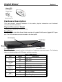
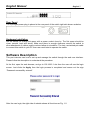
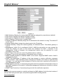
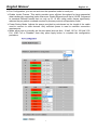
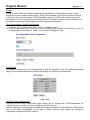
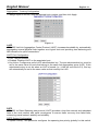
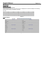
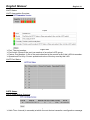
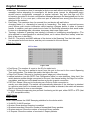
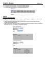
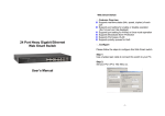
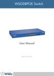
8 + 2 Port PoE Gigabit Web Smart Switch User Manual English LINDY No. 25051 For Home and Office Use Tested to Comply with FCC Standards www.LINDY.com © LINDY ELECTRONICS LIMITED & LINDY-ELEKTRONIK GMBH - FIRST EDITION (Dec 2011) English Manual English 2 Content Introduction .................................................................................................................................. 4 Product Overview.................................................................................................................. 4 Web Management Features ................................................................................................. 4 Specifications ........................................................................................................................ 5 Mechanical............................................................................................................................ 5 Performance ......................................................................................................................... 5 Package Contents................................................................................................................. 5 Hardware Description .................................................................................................................. 6 Physical Dimensions/ Weight ................................................................................................ 6 Front Panel ........................................................................................................................... 6 LED Indicators ...................................................................................................................... 6 Rear Panel ............................................................................................................................ 7 Hardware Installation ............................................................................................................ 7 Software Description .................................................................................................................... 7 Configuration ............................................................................................................................ 8 System .................................................................................................................................. 8 Ports ..................................................................................................................................... 9 VLAN .................................................................................................................................. 11 Aggregation ........................................................................................................................ 12 LACP .................................................................................................................................. 13 RSTP .................................................................................................................................. 13 IGMP Snooping .................................................................................................................. 15 Mirroring.............................................................................................................................. 16 Quality of Service (QoS) ..................................................................................................... 17 PoE (Power over Ethernet) Configuration ........................................................................... 20 Storm Control ...................................................................................................................... 21 Monitoring............................................................................................................................... 22 Statistic Overview ............................................................................................................... 22 Detailed Statics ................................................................................................................... 22 LACP Status ....................................................................................................................... 23 RSTP Status ....................................................................................................................... 23 IGMP Status ....................................................................................................................... 24 VeriPHY .............................................................................................................................. 25 Ping..................................................................................................................................... 26 Maintenance ........................................................................................................................... 28 English Manual English 3 Warm Restart ...................................................................................................................... 28 Factory Default ................................................................................................................... 28 Software upload .................................................................................................................. 28 Configuration File Transfer ................................................................................................. 29 Logout ................................................................................................................................. 29 Reset button for the factory default setting................................................................................. 29 English Manual English 4 Introduction Product Overview This switch is a Web Smart Switch equipped with 8-ports PoE+ 10/100/1000BaseT(X) plus 2port gigabit SFP. It is designed for easy installation and high performance in an environment where traffic is on the network and the number of users increased continuously. The compact rigid 19” rack-mount size is specifically designed for small to medium workgroups. It can be installed where space is limited; moreover, it provides smooth network migration and is easy to upgrade the network capacity. In addition, the switch features comprehensive and useful functions, such as: QoS (Quality of Service), Spanning Tree, VLAN, Power over Ethernet (PoE), Link Aggregation, SNMP/RMON, IGMP Snooping capability via the intelligent software. It is suitable for both metro-LAN and office application. Web Management Features Configuration System Ports VLANs Aggregation LACP RSTP IGMP Snooping Mirroring Quality of Service Power over Ethernet Storm Control Monitoring Statistics Overview Detailed Statistics LACP Status RSTP Status IGMP Status VeriPHY Ping Maintenance Warm Restart Factory Default Software Upload Configuration File Transfer Logout English Manual English 5 Specifications Standard IEEE 802.3 10BaseT IEEE 802.3u 100BaseTX IEEE 802.3ab 1000BaseT IEEE 802.3af PoE IEEE 802.3at PoE+ IEEE 802.3z 1000BaseSX/LX IEEE 802.3x Full-duplex Flow Control IEEE 802.3ad Link Aggregation IEEE 802.1Q VLAN IEEE 802.1d Spanning tree protocol IEEE 802.1w Rapid Spanning tree protocol IEEE 802.1p QoS Number of Port 8-port PoE+ 10/100/1000BaseT(X) with 2 Gigabit SFP Open Slots Mechanical LED Indicator Port 1~8: Link/ Act, 1000M, PoE Port 7FX, 8FX: Link Per Unit: Power Power Consumption: 130/260 Watts (Max), 30 Watts per port Power Input: 100~240V/AC, 50~60HZ Product Dimensions/ Weight: 440 × 220 × 44 mm (L x D x H ) / 3.2kg Performance MAC Address & Multicast group: 8K Buffer Memory: 176 KB Jumbo Frames: 9.6K Transmission Method: Store and Forward Package Contents Before you start to install this switch, please verify your package that contains the following items: One PoE Gigabit Ethernet Switch One AC Power Cord One CD : User Manual Rack-mount kit English Manual English 6 Hardware Description This part primarily presents hardware of this switch, physical dimensions and functional overview would be described. Physical Dimensions/ Weight 440 × 220 × 44 mm (L x D x H ) / 3.2kg Front Panel The front Panel of the Web Smart Switch consists of 8 gigabit RJ-45 ports+2 gigabit SFP open slot. The LED Indicators are also located on the front panel. LED Display RJ-45 Port Reset SFP Open Slot LED Indicators The LED Indicators present real-time information of systematic operation status. The following table provides description of LED status and their meaning. Table 1-1 LED Indicators LED Status Description On Power is on. Off Power is off. 7FX / 8FX Link On SFP Module is connected Off SFP Module is disconnected Link/ACT Port 1~8 On 10/100/1000 Link is connected Off 10/100/1000 Link is disconnected 1000M Port 1~8 On Link 1000Mbps Off Link 10/100Mbps PoE Port 1~8 On providing the power off not providing the power Power English Manual English 7 Rear Panel The 3-pronged power plug is placed at the rear panel of the switch right side shown as below. Hardware Installation Set the switch on a large flat space with a power socket close by. The flat space should be clean, smooth, level and sturdy. Make sure there is enough clearance around the switch to allow attachment of cables, power cord and allow air circulation. The last, use twisted pair cable to connect this switch to your PC then user could start to operate the switch. Software Description This part instructs user how to set up and manage the switch through the web user interface. Please follow the description to understand the procedure. At the first, open the web browser, and go to 192.168.2.1 site then the user will see the login screen. Just clicks the Apply then the login process is completed and comes out the sign “Password successfully entered”. Figure 1-1 After the user login, the right side of website shows all functions as Fig. 1-2. English Manual English 8 Figure 1-2 Configuration System System Configuration This page shows system configuration information. User can configure lots of information as Fig. 1-3: English Manual English 9 Figure 1-3 MAC Address: Displays the unique hardware address assigned by manufacturer (default). S/W Version: Displays the switch’s firmware version. H/W Version: Displays the switch’s Hardware version. DHCP Enabled: Click the box to enable DHCP Fallback IP address: Manually assign the IP address that the network is using. The default IP is 192.168.2.1 Fallback Subnet Mask: Assign the subnet mask to the IP address Fallback Gateway: Assign the network gateway for industrial switch. The default gateway is 0.0.0.0. Management VLAN: ID of a configured VLAN (1-4096) through which you can manage the switch. By default, all ports on the switch are members of VLAN 1. However, if the management VLAN is changed, the management station must be attached to a port belonging to this VLAN. Name: Type in the new user name (The default value is ‘admin’). Password: Type in the new password (The default value is ‘admin’). SNMP Enabled: Enables or disables SNMP on the switch. Supports SNMP version 1and 2c management clients. SNMP Trap Destination: IP address of the trap manager to receive notification messages from this switch. Traps indicating status changes are issued by the switch to specified trap managers. You must specify trap managers so that key events are reported by this switch to your management station. SNMP Read Community: A community string that acts like a password and permits access to the SNMP database on this switch. Authorized management stations are only able to retrieve MIB objects. SNMP Trap Community: Community string sent with the notification operation. Ports Port Security ensures access to a switch port based on MAC address, limits the total number of devices from using a switch port, and protects against MAC flooding attacks. Port Configuration English Manual English 10 In Port Configuration, you can set and view the operation mode for each port. Enable Jumbo Frames: This switch provides more efficient throughput for large sequential data transfers by supporting jumbo frames on Gigabit Ethernet ports up to 9.6 KB. Compared to standard Ethernet frames that run only up to 1.5 KB, using jumbo frames significantly reduces the per-packet overhead required to process protocol encapsulation fields. Power Saving Mode: Adjusts the power provided to ports based on the length of the cable used to connect to other devices. Only sufficient power is used to maintain connection requirements. Mode: allow user to manually set the port speed such as Auto, 10 half, 10 Full, 100 Half, 100 Full, 1000 Full or Disabled. User may press Apply button to complete the configuration procedure. Figure 1-4-1 Figure 1-4-2 English Manual English 11 VLAN A Virtual LAN (VLAN) is a logical network grouping that limits the broadcast domain, which would allow you to isolate network traffic, so only the members of the same VLAN will receive traffic from the ones of the same VLAN. Basically, creating a VLAN from a switch is logically equivalent of reconnecting a group of network devices to another Layer 2 switch. However, all the network devices are still plugged into the same switch physically. Port Segmentation (VLAN) Configuration VLAN ID: ID of configured VLAN (1-4096, no leading zeroes). VLAN Configuration List: Lists all the current VLAN groups created for this system. Up to 16 VLAN groups can be defined. VLAN 1 is the default untagged VLAN. Figure 1-5-1 VLAN Setup The switch supports up to 16 VLANs based on 802.1Q standard. From the VLAN Membership page you can create and delete VLANs, and change the VLAN port membership. Figure 1-5-2 VLAN Per Port Configuration The 802.1Q Per Port Configuration page allows you to change the VLAN parameters for individual ports or trunks. You can configure VLAN behavior for specific interfaces, including the accepted frame types and default VLAN identifier (PVID). Each row of the table corresponds to one port or trunk; trunked ports cannot be configured individually; configure the trunk instead. English Manual English 12 Figure 1-5-3 Port/Trunk: The port number of the port or the ID of a trunk. VLAN Aware Enabled: VLAN aware ports are able to use VLAN tagged frames to determine the destination VLAN of a frame. (Default: Enabled) VLAN aware ports will strip the VLAN tag from received frames and insert the tag in transmitted frames (except for the PVID). VLAN unaware ports will not strip the tag from received frames or insert the tag in transmitted frames. Ingress Filtering Enabled: If enabled, incoming frames for VLANs which do not include this ingress port in their member set will be discarded. (Default: Disabled) Packet Type: Sets the interface to accept all frame types, including tagged or untagged frames, or only tagged frames. (Default: All) If the Packet Type is set to “All,” the port can accept incoming tagged and untagged packets. Any received packets that are untagged are assigned to the default VLAN. Any tagged packets will be dropped unless the port is a member of the VLAN identified by the VLAN tag in the packet. If the Packet Type is set to “Tagged Only,” the port will drop untagged packets and will only receive tagged packets. Tagged packets will be dropped unless the port is a member of the VLAN identified by the VLAN tag in the packet. Switches should be connected to each other with the Packet Type set to “Tagged Only.” PVID: The PVID (Port VLAN ID) is associated with untagged, ingress packets. It is assigned to untagged frames received on the specified interface. The PVID has no effect on ports that have Packet Type set to “Tagged Only.” (Default PVID: 1) It is not possible to remove a port from VLAN 1 unless its PVID has been changed to something other than 1. Outgoing packets are tagged unless the packet’s VLAN ID is the same as the PVID. When the PVID is set to “None,” all outgoing packets are tagged. ※Note: If you select “Tagged Only” mode for a port, we recommend setting the PVID to “None” as the standard configuration. Aggregation Port trunk allows multiple links to be bundled together and act as a single physical link for increased throughput. It provides load balancing, and redundancy of links in a switched internetwork. Actually, the link does not have an inherent total bandwidth equal to the sum of its component physical links. Traffic in a trunk is distributed across an individual link within the trunk in a deterministic method that called a hash algorithm. The hash algorithm automatically applies load balancing to the ports in the trunk. A port failure within the trunk group causes the network traffic to be directed to the remaining ports. Load balancing is maintained whenever a link in a trunk is lost or returned to service. English Manual English 13 Aggregation / Trunking Configuration To assign a port to a trunk, click the required trunk number, and then click Apply. Figure 1-6 LACP IEEE 802.3ad Link Aggregation Control Protocol (LACP) increases bandwidth by automatically aggregating several physical links together as a logical trunk and providing load balancing and fault tolerance for uplink connections. LACP Port Configuration Port: The port number. Enabled: Enables LACP on the associated port. Key Value: Configures a port's LACP administration key. The port administrative key must be set to the same value for ports that belong to the same link aggregation group (LAG). If this administrative key is not set when an LAG is formed (i.e., it has the null value of 0), this key will automatically be set to the same value as that used by the LAG. Figure 1-7 RSTP IEEE 802.1w Rapid Spanning tree protocol (LACP) provides a loop-free network and redundant links to the core network with rapid convergence to ensure faster recovery from failed links, enhancing overall network stability and reliability. RSTP System Configuration System Priority: This parameter configures the spanning tree priority globally for this switch. English Manual English 14 The device with the highest priority becomes the STP root device. However, if all devices have the same priority, the device with the lowest MAC address will then become the root device. Hello Time: Interval (in seconds) at which the root device transmits a configuration message (BPDU frame). Number between 1-10 (default is 2). Max Age – The maximum time (in seconds) a device can wait without receiving a configuration message before attempting to reconfigure. That also means the maximum life time for a BPDU frame. Number between 6-40 (default is 20). Forward Delay: The maximum time (in seconds) the root device will wait before changing states (i.e., discarding to learning to forwarding). Number between 4 – 30 (default is 15). Force Version: Set and show the RSTP protocol to use. Normal - use RSTP, Compatible compatible with STP. Figure 1-8-1 RSTP Port Configuration Port: The port ID. It cannot be changed. Aggregations mean any configured trunk group. Enabled: Click on the tick-box to enable/disable the RSTP protocol for the port. Edge: Expect the port to be an edge port (linking to an end station) or a link to another STP device. Path Cost: This parameter is used by the STP to determine the best path between devices. Therefore, lower values should be assigned to ports attached to faster media, and higher values assigned to ports with slower media. Set the RSTP pathcost on the port. Number between 0 - 200000000. 0 means auto generated pathcost. Figure 1-8-2 English Manual English 15 Figure 1-8-3 Figure 1-8-4 IGMP Snooping IGMP Snooping is the process of listening to IGMP network traffic. IGMP Snooping, as implied by the name, is a feature that allows a layer 2 switch to “listen in” on the IGMP conversation between hosts and routers by processing the layer3 IGMP packets sent in a multicast network. When IGMP Snooping is enabled in a switch it analyzes all IGMP packets between hosts connected to the switch and multicast routers in the network. When a switch hears an IGMP report from a host for a given multicast group, the switch adds the host’s port number to the multicast list for that group. And, when the switch hears an IGMP Leave, it removes the host’s port from the table entry. Prevents flooding of IP multicast traffic, and limits bandwidth intensive video traffic to only the subscribers. IGMP Configuration IGMP Enabled: When enabled, the switch will monitor network traffic to determine which hosts want to receive multicast traffic. Router Ports: Set if ports are connecting to the IGMP administrative routers. Unregistered IPMC Flooding enabled: Set the forwarding mode for unregistered (not-joined) IP multicast traffic. The traffic will flood when enabled, and forward to router-ports only when disabled. IGMP Snooping Enabled: When enabled, the port will monitor network traffic to determine which hosts want to receive the multicast traffic. IGMP Querying Enabled: When enabled, the port can serve as the Querier, which is responsible for asking hosts if they want to receive multicast traffic. English Manual English 16 Figure 1-9-1 Mirroring Port Mirroring is used on a network switch to send a copy of network packets seen on one switch port (or an entire VLAN) to a network monitoring connection on another switch port. This is commonly used for network appliances that require monitoring of network traffic, such as an intrusion-detection system. Mirroring Configuration Port to Mirror to: The port that will “duplicate” or “mirror” the traffic on the source port. Only incoming packets can be mirrored. Packets will be dropped when the available egress bandwidth is less than ingress bandwidth. Ports to Mirror: Select the ports that you want to mirror from this section of the page. A port will be mirrored when the “Mirroring Enabled” check-box is checked. Figure 1-10-1 English Manual English 17 Figure 1-10-2 Quality of Service (QoS) In QoS Mode, select QoS Disabled, 802.1p, or DSCP to configure the related parameters. QoS Configuration Strict: Services the egress queues in sequential order, transmitting all traffic in the higher priority queues before servicing lower priority queues. WRR: Weighted Round-Robin shares bandwidth at the egress ports by using scheduling weights with default values of 1, 2, 4, 8 for queues 0 through 7, respectively. (This is the default selection.) ※Note: WRR can only be selected if Jumbo Frame mode is disabled on the Port Configuration page Figure 1-11-1 QoS Mode: QoS Disabled When the QoS Mode is set to QoS Disabled, the following table is displayed. English Manual English 18 Figure 1-11-2 QoS Mode: 802.1p Packets are prioritized using the 802.1p field in the VLAN tag. This field is three bits long, representing the values 0 - 7. When the QoS Mode is set to 802.1p, the 802.1p Configuration table appears, allowing you to map each of the eight 802.1p values to a local priority queue (low, normal, medium or high). The default settings are shown below. When the QoS Mode is set to 802.1p, the 802.1p Configuration table is displayed as shown below. Figure 1-11-3 English Manual English 19 Figure 1-11-4 QoS Mode: DSCP DSCP: Packets are prioritized using the DSCP (Differentiated Services Code Point) value. The Differentiated Services Code Point (DSCP) is a six-bit field that is contained within an IP (TCP or UDP) header. The six bits allow the DSCP field to take any value in the range 0 - 63. When QoS Mode is set to DSCP, the DSCP Configuration table is displayed, allowing you to map each of the DSCP values to a hardware output queue (low, normal, medium or high). The default settings map all DSCP values to the high priority egress queue. User can use the Prioritize Traffic drop-down list to quickly set the values in the DSCP Configuration table to a common priority queue. Use Custom if you want to set each value individually. When the QoS Mode is set to DSCP, the DSCP Configuration table is displayed as shown below. Figure 1-11-5 English Manual English 20 Figure 1-11-6 PoE (Power over Ethernet) Configuration Power over Ethernet (PoE) is an advanced technology providing a whole new application aspect for networking products. A series of PoE product is powering for wide range of devices, especially useful for VoIP phones, wireless LAN access points and IP cameras. It is deployed in applications where AC power would be inconvenient, expensive or infeasible to supply. Web Smart features are able to remote control and centralized the power management. Via a current CAT 5 cable, power and data are able to travel though. Not only is it saving costs, but also it meets the demand of energy efficiency. PoE Configuration Remote access and monitor the attached PD (Powered Device) status by using Enable/Disable function. PoE Enabled: POE of the port is able to supply power to the attached PD (Powered Device) PD Class: Detect the class of PD Delivering Power (W): Output power Current (mA): The status of the port current Power Budget: Total PoE power has been used Figure 1-12-1 English Manual English 21 Storm Control Broadcast storms may occur when a device on your network is malfunctioning, or if application programs are not well designed or properly configured. If there is too much broadcast traffic on your network, performance can be severely degraded or everything can come to complete halt. You can protect your network from broadcast storms by setting a threshold for broadcast traffic for each port. Any broadcast packets exceeding the specified threshold will then be dropped. Storm Control Configuration There are three type of traffic which can be rate limited, including broadcast multicast frame and Flooded Uncast Rate. Figure 1-13-1 Enable Rate Limit: Click the check box to enable storm control. Rate (number of frames per second): The Rate field is set by a single drop-down list. The same threshold is applied to every port on the switch. When the threshold is exceeded, packets are dropped, irrespective of the flow-control settings. Web: Click PORTS, Storm Control. This page enables you to set the broadcast storm control parameters for every port on the switch. Figure 1-13-2 English Manual English 22 Monitoring Statistic Overview Statistic Overview for all ports User can mirror traffic from any source port to a target port for real-time analysis the following figures shows clearly the statistics overview. Figure 2-1 Detailed Statics Figure 2-2 English Manual English 23 LACP Status LACP Aggregation Overview Figure 2-3-1 Port: The port number. Port Active: Shows if the port is a member of an active LACP group. Partner Port Number: A list of the ports attached at the remote end of this LAG link member. Operational Port Key: Current operational value of the key used by this LAG. LACP Port Status Figure 2-3-2 RSTP Status RSTP VLAN Bridge Overview Figure 2-4-1 Hello Time: Interval (in seconds) at which the root device transmits a configuration message. English Manual English 24 Max Age: The maximum time (in seconds) a device can wait without receiving a configuration message before attempting to reconfigure. All device ports (except for designated ports) should receive configuration messages at regular intervals. Any port that age out STA information (provided in the last configuration message) becomes the designated port for the attached LAN. If it is a root port, a new root port is selected from among the device ports attached to the network. Fwd Delay: The maximum time (in seconds) the root device will wait before changing states (i.e., discarding to learning to forwarding). This delay is required because every device must receive information about topology changes before it starts to forward frames. In addition, each port needs time to listen for conflicting information that would make it return to a discarding state; otherwise, temporary data loops might result. Topology: Indicates if spanning tree topology is steady or undergoing reconfiguration. (The time required for reconfiguration is extremely short, so no values other that “steady” state are likely to be seen in this field.) Root ID : The priority and MAC address of the device in the Spanning Tree that this switch has accepted as the root device, and the port connected to the root device. RSTP Port Status Figure 2-4-2 Port/Group: The number of a port or the ID of a static trunk. Path Cost: The cost for a packet to travel from this port to the root in the current Spanning Tree configuration. The slower the media, the higher the cost. Edge Port: Shows if this port is functioning as an edge port, either through manual selection (see the RSTP Port Configuration table) or auto-detection. Note that if the switch detects another bridge connected to this port, the manual setting for Edge Port will be overridden, and the port will instead function as a point-to-point connection. P2P Port: Shows if this port is functioning as a Point-to-Point connection to exactly one other bridge. The switch can automatically determine if the interface is attached to a point-to-point link or to shared media. If shared media is detected, the switch will assume that it is connected to two or more bridges. Protocol: Shows the spanning tree protocol functioning on this port, either RSTP or STP (that is, STP-compatible mode). IGMP Status IGMP Status IGMP Status shows the IGMP Snooping statistics for the whole switch. VLAN ID: VLAN ID number. Querier: Show whether Querying is enabled. Queries transmitted: Show the number of transmitted Query packets. Queries received: Show the number of received Query packets. v1 Reports: Show the number of received v1 Report packets. English Manual English 25 v2 Reports: Show the number of received v2 Report packets. v3 Reports: Show the number of received v2 Report packets. v3 Leave: Show the number of v3 leave packets received. Figure 2-5 VeriPHY VeriPHY Cable Diagnostics User can perform cable diagnostics for all ports or selected ports to diagnose any cable faults (short, open etc..) and feedback a distance to the fault. Cable Diagnostics: Cable diagnostics is performed on a per-port basis. Select the port number from the drop-down list. Cable Status: Shows the cable length, operating conditions and isolates a variety of common faults that can occur on Category 5 twisted pair cabling. Figure 2-6-1 Figure 2-6-2 English Manual English 26 Figure 2-6-3 Figure 2-6-4 Ping This command sends ICMP echo request packets to another node on the network. Ping Parameters Target IP Address: IP address of the host Count: Number of packets to send. (Range: 1-20) Time Out: setting the time period of host will be Ping Use the ping command to see if another site on the network can be reached. The following are some results of the ping command: Normal response: The normal response occurs in one to ten seconds, depending on network traffic. Destination does not respond: If the host does not respond, a “timeout” appears in ten seconds. Destination unreachable: The gateway for this destination indicates that the destination is unreachable. Network or host unreachable: The gateway found no corresponding entry in the route table. Press <Esc> to stop pinging. English Manual English 27 Figure 2-7-1 Figure 2-7- English Manual English 28 Figure 2-7-3 Maintenance Warm Restart Press Yes button to restart the switch, the reset will be complete when the power lights stop blinking. Figure3-1 Factory Default This function is to force the switch back to the original factory settings. To reset the switch, select “Reset to Factory Defaults” from the drop-down list and click Apply. The LAN IP Address, Subnet Mask and Gateway IP Address will be reset to their factory Figure 3-2 Software upload Select “Upgrade Firmware” from the Tools drop-down list then click on the “Browse” button to select the firmware file. Click the APPLY button to upgrade the selected switch firmware file. User can download firmware files for user’s switch from the Support section of your local supplier. English Manual English 29 Figure 3-3 Configuration File Transfer Configuration file transfer allows you to save the switch’s current configuration or restore a previously saved configuration back to the device. Configuration files can be saved to any location on the web management station. “Upload” the configuration file to save a configuration or "Download" to restore a configuration. Use the Browse button to choose a file location on the web management station, or to find a saved configuration file. Figure 3-4 Logout The administrator has write access for all parameters governing the onboard agent. User should therefore assign a new administrator password as soon as possible, and store it in a safe place. Figure 3-5 Reset button for the factory default setting Please take the following steps to reset the Web Smart Switch back to the original default: Step 1: Turn on the Web Smart Switch Step 2: Press and hold the reset button continuously for 5 seconds and release the reset button. Step 3: The switch will reboot for 20 seconds and the configuration of switch will back to the default setting. Radio Frequency Energy, Certifications FCC Warning This device complies with part 15 of the FCC Rules. Operation is subject to the following two conditions: 1. This device may not cause harmful interference, and 2. This device must accept any interference received, including interference that may cause undesired operation. CE Statement, EMC Compatibilty This device complies with EN Standards EN55022 and EN55024 according to the relevant EC EMC Directive. It must be used with shielded cables only to maintain EMC compatibility. Dieses Produkt entspricht den einschlägigen EMV Richtlinien der EU und darf nur zusammen mit abgeschirmten Kabeln verwendet werden. LINDY Herstellergarantie LINDY gewährt für dieses Produkt über die gesetzliche Regelung hinaus eine zweijährige Herstellergarantie ab Kaufdatum. Die detaillierten Bedingungen dieser Garantie finden Sie auf der LINDY Website aufgelistet bei den AGBs. WEEE (Waste of Electrical and Electronic Equipment), Recycling of Electronic Products In 2006 the European Union introduced regulations (WEEE) for the collection and recycling of all waste electrical and electronic equipment. The wheelie bin symbol shown indicates that this product must not be disposed of with household waste. Instead the product must be recycled in a manner that is environmentally friendly. For more information on how to dispose of this product, please contact your local recycling centre or your household waste disposal service. Each individual EU member state has implemented the WEEE regulations into national law in slightly different ways. Please follow your national law when you want to dispose of any electrical or electronic products. More details can be obtained from your national WEEE recycling agency. Germany / Deutschland Die Europäische Union hat mit der WEEE Direktive umfassende Regelungen für die Verschrottung und das Recycling von Elektro- und Elektronikprodukten geschaffen. Diese wurden von der Bundesregierung im Elektro- und Elektronikgerätegesetz – ElektroG in deutsches Recht umgesetzt. Dieses Gesetz verbietet vom 24.März 2006 an das Entsorgen von Elektro- und Elektronikgeräten über die Hausmülltonne! Diese Geräte müssen den lokalen Sammelsystemen bzw. örtlichen Sammelstellen zugeführt werden! Dort werden sie kostenlos entgegen genommen. Die Kosten für den weiteren Recyclingprozess übernimmt die Gesamtheit der Gerätehersteller. LINDY No 25051 1st Edition, December 2011 www.lindy.com