1
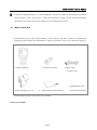
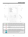
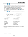
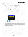
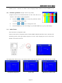
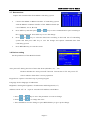
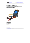
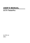
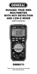
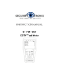
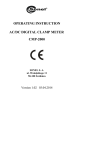
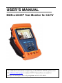
USER’S MANUAL MON-LCD35P Test Monitor for CCTV For additional information and pricing on the MON-LCD35P, please visit the online product page or contact CCTV Camera Pros via email at [email protected] or by telephone at 561-433-8488. MON-LCD35P User’s Manual Thank you for purchasing the CCTV security tester. Please read the manual before using the MON-LCD35P, and use properly. For using the MON-LCD35P safely, please first read the「Safety Information」carefully in the manual. The manual should be kept well in case of reference. Keep the S/N label for after-sale service within warranty period. Product without S/N label will be charged for repair service. If there is any question or problem while using the MON-LCD35P, or damages occurred on the product, please contact our technical Department. Page.1. MON-LCD35P User’s Manual Table of Content 1 S a f e t y I n f o r m a t i o n -----------------------------------------------------------------------------------3 2 I n t r o d u c t i o n ----------------------------------------------------------------------------------------------4 2.1 Features --------------------------------------------------------------------------------------------------4 2.2 MON-LCD35P Kits ---------------------------------------------------------------------------------5 2.3 Front Panel-----------------------------------------------------------------------------------------------6 2.4 Side View-------------------------------------------------------------------------------------------------8 2.5 Installing the Battery-----------------------------------------------------------------------------------9 3 Operation----------------------------------------------------------------------------------------------------10 3.1 Power on/off--------------------------------------------------------------------------------------------10 3.2 Menu & Functions-------------------------------------------------------------------------------------10 3.3 PTZ controller------------------------------------------------------------------------------------------12 3.4 Video setting -------------------------------------------------------------------------------------------15 3.5 Colorbar generator -----------------------------------------------------------------------------------15 3.6 Cable tester---------------------------------------------------------------------------------------------16 3.7 Data monitor -------------------------------------------------------------------------------------------17 3.8 Device setting------------------------------------------------------------------------------------------17 3.9 Address search----------------------------------------------------------------------------------------18 3.10 Digital multimeter-----------------------------------------------------------------------------------19 4 DC12V Power output------------------------------------------------------------------------------------26 5 Audio input test-------------------------------------------------------------------------------------------26 6 Specifications --------------------------------------------------------------------------------------------27 6.1 General specifications------------------------------------------------------------------------------27 6.2 Multimeter specifications--------------------------------------------------------------------------28 Page.2. MON-LCD35P User’s Manual 1. Safety Information Notice This CCTV test monitor is intended to use in compliance with the local rules of the electrical usage and avoid to apply at the places which are inapplicable for the use of electrics such as hospital, gas station etc. To prevent the functional decline or failure, the product should not be sprinkled or damped. The exposed part of the tester should not be touched by the dust and liquid. During transportation and use, it is highly recommended to avoid the violent collision and vibration of the tester, lest damaging components and causing failure. Don’t leave the tester alone while charging and recharging. If the battery is found severely hot, the tester should be powered off from the electric source at once. The test should not be charged over 8 hours. Don’t use the tester where the humidity is high. Once the tester is damp, power off immediately and move away other cables connected. The tester should not be use in the environment with the flammable gas. Do not disassembly the instrument since no component inside can be repaired by the user. If the disassembly is necessary indeed, please contact with the technician of our company. The instrument should not be used under the environment with strong electromagnetic interference. Don’t touch the tester with wet hands or waterish things. Don’t use the detergent to clean and the dry cloth is suggested to use. If the dirt is not easy to remove, the soft cloth with water or neutral detergent can be used., but the cloth should be tweaked sufficiently. About digital multimeter Before using,you must select the right input jack, function and range. Never exceed the protection limit values indicated in specifications for each range of measurement. When the meter is linked to a measurement circuit, do not touch unused terminals. Do not measure voltage if the voltage on the terminals exceeds 660V above earth ground. At the manual range, when the value scale to be measured is unknown beforehand, set the range selector at the highest position. Always be careful when working with voltages above 60V DC or 30V AC, keep fingers behind the probe barriers while measuring. Never connect the meter with any voltage source while the function switch is in the current, resistance, capacitance, diode, continuity, otherwise it will damage the meter. Never perform capacitance measurements unless the capacitor to be measured has been discharged fully. Never measure any of resistance, capacitance, diode or continuity measurements on live circuits. Page.3. MON-LCD35P User’s Manual 2. Introduction The MON-LCD35P is developed for the On-Site installation and maintenance of CCTV video monitoring systems. It can be used for displaying video, controlling PTZ, generating images, capturing data of RS485 and testing LAN cable etc. Its functions, easy operation, and portability makes it simple for the CCTV technician to install and maintain CCTV system, improving work efficiency and get the labor cost down. 2.1 Features 3.5"TFT-LCD , 960(H)×240(V)resolution. Video Level testing, video signals measured in IRE or mV DC12V 1A power output for camera Audio input testing Digital multimeter, voltage, current, resistance and capacitance can be tested, continuity testing, diode testing. PTZ control. Pan/tilts the P/T unit, zooms in/out the lens, adjusts the focus, aperture and sets and calls the preset position Video displaying. Automatically adapts and displays the video format of NTSC/PAL. LCD Brightness/Contrast/Color Saturation are adjustable. Video Generating, The PAL/NTSC multi-system colorbar video generator (seven-system switchable, transmit/receive seven-system colorful imagines) Data analyst. Captures and analyzes RS485 controlling data to help the technician to find out the problem. Cable testing. It is powerful in testing LAN cable, measuring the connecting status ,displaying the sequence of connection and the NO. of the LAN cable. Multi-interface and Multi-baud rate. Support RS232 ,RS485 and RS422 interface; baud rate ranging from 150, 600 to 19200bps. Multi-protocol. Supports more than twenty PTZ protocols. For example, PELCO-P, PELCO-D, SAMSUNG etc. PTZ address scanning, search up the ID of PTZ camera. Page.4. MON-LCD35P User’s Manual Lithium Ion Polymer Battery (3.7V DC3000mAh). The device employs advanced power control and protection circuit. The device is high power-efficient, energy saving and environmental protection. It can last 12 hours for normal use after charging for 4 hours. 2.2 MON-LCD35P Kits Professional design, light and portability, video display and data control are deliberately integrated, which makes the instrument so simple, practicable, easy for use that the training is 1. MON-LCD35P 3. LAN Cable Tester 5. BNC Cable 6. Safety cord 7. RS485 data cable 2. Power Supply (5V 2A) 4. Lithium Ion Polymer Battery almost unnecessary for an operator to be skillful. 2.3 F r o n t P a n e l Page.5. 8. Instruction Manual MON-LCD35P User’s Manual 1 The power indicator: it lights green while the tester is powered on. 2 The data-reception indicator: it lights red while the data is being received. The data-transmission indicator: it lights red while the data is being 3 transmitted The charge indicator: it lights red while the battery is being charged. As 4 the charging is complete, the indicator turns off automatically. 5 The display Icon of battery electricity: it displays the electric quantity 6 Main-menu: it shows main functions of MON-LCD35P. 7 Sub-menu: Shows and sets the values of functions Page.6. MON-LCD35P User’s Manual Long-pressing it more than 2 seconds to turn on/off the tester; 8 short-pressing to turn on/off the PTZ controller menu displaying. Menu key: it pops up the main-menu; constant-press it or press the 9 or key can shift between functions Setup key : press it or press left or right key to enter sub-menu to set the 10 parameters of functions. Upward : Select the item which will be set or add the value of the 11 parameter. Tilt the PTZ upward. Leftward : Enter the sub-menu or select the parameter whose value will be 12 changed. Reduce the value of the parameter. Pan the PTZ left. Rightward : Enter the sub-menu or select the parameter whose value will 13 be changed. Add the value of the parameter. Pan the PTZ right. Downward : Select the item which will be set or reduce the value of the 14 parameter. Tilt the PTZ downward. 15 Confirm/Open : Confirm the setting of parameters; open the aperture. Return/Close : Return or cancel while setting parameters of the menu; 16 close the aperture 17 Near focus: Focus the image nearby. 18 Far focus: Focus the image faraway. 19 TELE: zoom in the image 20 WIDE: zoom out the image 21 Digital multimeter Page.7. MON-LCD35P User’s Manual 2.4 Side view 22 Reset the default settings of parameters. 23 External power supply (DC, 5V): It is highly recommended to use the equipped power adapter. 24 UTP cable port: Please use together with UTP LAN cable tester. 25 RS232 interface: RS232 communication for the PTZ. 26 Audio input: test the pickup and other audio equipments on the front-end 27 DC12V1A power output: output DC12V power for camera 28 Tester speaker 29 Video input (BNC input interface): Inputs the video. 30 Video output (BNC output interface): Outputs the video. 31 RS485/422 Interface: RS485/RS422 communication for the PTZ. Page.8. MON-LCD35P User’s Manual 2. 5 I nstal l i n g th e Bat ter y The tester has built-in lithium ion polymer rechargeable battery. The battery cable inside battery cabin should be disconnected for safety during transportation! Prior to the use of the instrument, the battery cables inside the battery cabin should be well connected. Usually it need not to disconnect the cable at the normal use, pressing key continuously can power on or off the tester. At the first time of use, the batteries should be completely exhausted and then recharged for 4 or 5 hours. The Charge Indicator lights red when charging the battery, The charge indicator turns off automatically when the charging is completed. △ Notice: When the Charge Indicator turns off, the battery is approximately 90% charged. The charging time can be extended for about 1 hour and the charging time within 8 hours will not damage the battery. △ The tester can work as usual while it is being charged, however. But the charging time will be extended. Press the RESET key at the right of the instrument to restore the default settings instrument works abnormally. Page.9. when the MON-LCD35P User’s Manual 3. Operation 3.1 Power on Continuously press (at least 2 seconds) to power on/off the MON-LCD35P. When the MON-LCD35P is powered on,press MODE key the main-menu will pop up. 3.2 Menu & Functions Press MODE key continuously or press the or key to select the function (PTZ controller, Video settings, Colorbar generator, LAN cable tester, Data monitors, Device setting) and enter corresponding function setting sub-menu. Press SET key to set the parameters in function sub-menu. Note: When the MON-LCD35P is powered on, it will return to the function which is being operated before it is turned off. 1. PTZ controller Display the input video images. Pan/tilt the P/T unit and zoom in/ out the image. Setup the controlling parameters like p rotocol, communication port, baud rate, PTZ ID, pan/tilt speed; set and call preset position. Page.10. MON-LCD35P User’s Manual 2. Video setting Adjust the LCD brightness, Contrast, Color saturation. Video Format and Video level testing 3. Colorbar generator Output or receive seven different forms of video color bar to tester monitor, cable or other equipment. 4. Cable tester Test LAN cable or telephone cable. The connecting condition and the sequence of wires will be displayed, as well as the serial number of the cable tester kit. 5. Data Monitor Captures the protocol from the controlling system and display command data. It is helpful to debug and maintain RS485 communication. 6. Device setting Set the parameters of the MON-LCD35P (Auto power off/ Keypad tone/Language/Brightness/Address search) Page.11. MON-LCD35P User’s Manual 7. Address search Search the ID of PTZ camera 8. Digital Multimeter Digital Multimeter performs AD/DC Voltage, AC/DC Current, Resistance, Continuity, Capacitance and Diode test, Auto / Manual Range, Data hold, Relative measuring. 3.3 PTZ Controller Display the input video images. Pan/tilt the P/T unit and zoom in/ out the image. Setup the controlling parameters like protocol, communication port, baud rate, PTZ ID, pan/tilt speed; set and call preset position. The following connections should be confirmed before use a. The Video In interface of the MON-LCD35P and the output interface of camera b. Data A+ of the MON-LCD35P and A+ of the PTZ camera or controlling device, data B- of the instrument and B- of the PTZ camera or controlling device Note: Don’t connect communications interface with a circuit the voltage higher than 6V. Page.12. MON-LCD35P User’s Manual a. Press SET key to enter the sub-menu of PTZ controller. b. Press the or key to select the parameter which we want to change the value. c. Press ENTER key to save the change or press RETURN key to give up the change d. Press SET key to exit the sub-menu. e. Press POWER key to full-screen the image A. Protocol: Select the protocol according to the protocol of the PTZ camera. Up to 21 popular protocols are available, like elco P, Pelco D, Samsung, Yaan, LiLin, CSR600 etc. B. Port: Select the communication port for the PTZ camera controlling (RS232/422/485) C. Baud: Select the baudrate according to baudrate of the PTZ camera.(150, 300, … , 19200bps) D. Address: Set the ID according the ID of PTZ camera (0~254). E. Pan Speed: Set the pan speed of PTZ camera (0~63) F. TiltSpeed: Set the tilt speed of PTZ camera (0~63) G. Set PS: Setup preset position (0~128) a. P/T/Z the camera to desired position b. Press SET key to enter PTZ controller submenu c. Move the yellow cursor to “Set PS” and then press or key to select the preset position number. d. Press ENTER key to complete preset position setting or pres et RETURN key to give up preset position setting. Tips: Press or key to accelerate the value changing. H. Go PS: Call the preset position. (0~128) The PTZ camera will go to the desired preset position. a. Move the yellow cursor to “Go PS” and then press or key to select the preset position number. b. Press ENTER key to complete preset position calling or preset RETURN key to give up preset position calling. Page.13. MON-LCD35P User’s Manual Tips: Press or key to accelerate the value changing. The way of calling the OSD menu and preset of the PTZ camera may vary with control systems from different manufacturers. Please read the operation manual of control system manufacturer for details. The way of calling OSD provided for reference is calling preset-64. a. Move the yellow cursor to “PTZ controller” to enter PTZ controller mode b. Press SET key to enter PTZ controller sub-menu. Press or key to move the yellow cursor to “Go PS”, c. Press or key to select the preset number 64, and then press ENTER key to call OSD menu of the PTZ controller. OSD Menu of Dome (For reference only) MAIN MENU MAIN MENU 1. DISPLAY SETUP 1. Display configuration 2. CAMERA SETUP 2. Set camera parameters. 3. CONTROL SETUP 3. Set PTZ controlling 4. CAMERA MASK SET 4. Set privacy mask 5. PROGRAM 5. Set auto-running functions 6. PAL CAMERA 6. PAL/NTSC Switch 7. CAM DEFAULT SET 7. Restore the default settings 8. DOME RESET 8. Reset the dome 9. EXIT 9. Exit the main menu Operate auto-running functions by calling preset position(effective for s ome brands of PTZ camera) Call preset-33—Open Auto-flip function Call preset-34—Reset zero point of PTZ camera Call preset-64—Enter the main menu of the PTZ camera Call preset-95—Enter the main menu of the PTZ camera or stop the PATTERN recording. Call preset-96—Run pattern-1 Call preset-97—Run preset tour-1 Call preset-98—Run frame Scan Page.14. MON-LCD35P User’s Manual Call preset-99—Run Auto scan 3.4. Video Setting User can customize the brightness, contrast and saturation of the LCD according to the using environment , the CCTV tester auto display the format(PAL/NTSC) of video input, and analysis the input video signal level. a. Press the or key to select the parameter which we want to change the value. b. Press the or key to change the value. Press ENTER key to save the change c. The Video Format and Video Level will be displayed in the lower portion of the screen. If or press RETUR key to give up the change there is no video signal at the Video IN port of the MON-LCD35P, the type of NTSC or PAL , and Video Level will not be displayed. Depending on the type of camera connected to the MON-LCD35P, the Video “Format: “ will automatically change between NTSC and PAL, and the Video Level will automatically change between IRE (Institute of Radio Engineers) and mV. NTSC signals measured in IRE units, PAL signals measured in mV. The Video Level should be within the indicated range. Levels that are too low will result in a dim picture with reduced dynamic range. A Video Level that is too high will result in washed out pictures with decreased. The MON-LCD35P will display “Normal” when video levels are Page.15. MON-LCD35P User’s Manual 1000mV±20%, 3.5. “Exceed” or “Weak” will be displayed when video level out of 1000mV±20%. Colorbar generator (Output video at any mode) Output or receive seven different forms of video color bar to test monitor, video cable or other equipment. a. Press the or key to select the parameter which we want to change the value. 3. 6 b. Press the c. Press ENTER key to save the change or press RETURN key to give up the change or key to change the value. Cable Tester Test LAN cable or telephone cable. Connect LAN cable or telephone cable with the MON-LCD35P and cable tester. And then the connecting status, cable type and the sequence of wires will be displayed, as well as the serial number of the cable tester kit The right picture shows line1-7 are closed, line8 is open and the number of the cable tester box is 255 Straight-through Line Cross Line Page.16. Open Line or Short Line MON-LCD35P User’s Manual 3.7. Data monitor Capture the command data from RS485 controlling system. a. Connect the RS485 or RS232 interface of controlling system with the RS485 or RS232 interface of the MON-LCD35P (In case of RS485, A to A, B to B) b. Press SET key and then press or key to select communication port according to the system connection. Press SET key to save the change. d. Press or key to select the baud rate according to the baud rate of controlling system and then press SET key to save the change and capture command data from controlling system. e. Press RETURN key to clear the screen. 3.8 Device setting Set the parameters of the MON-LCD35P Auto poweroff: Setting the time of auto shut-down.(Disable,5,10,…,60) Disable: Disable the “Auto poweroff” function. 5 means the CCTV will power off after 5 minutes when there is no any operation. Keypad tone: Open or close the beep of pressing keypad. Language: Select language of OSD menu Brightness: Setting the brightness of OSD menu and background.(0~7) Address search: off / on a. Press or b. Press or Open or close the PTZ address search Menu. key to move the parameter we want to change. to change the value. c. Press ENTER to save the change or press RETURN key to give up the change. Page.17. MON-LCD35P User’s Manual 3.9 PTZ address scanning Search up the ID of PTZ camera. Note: Please isolate the PTZ camera with other PTZ cameras before searching up. Otherwise all the PTZ cameras in the same system will pan at the same time. Press keys to “Device setting” Press key to confirm after change “Address search:” menu: to “on”, which add address scan sub-menu. Press to switch the sub-menu as illustrated: (Note: The system returns to “OFF” after shutdown, and the scan sub-menu closes automatically. Set “ON” again for next use.) Press key to set: protocol, communication port, communication rate, make them same as the PTZ camera Press or NEAR: key, the address values is constantly on the rise or decrease. The tester will search up the ID quickly and continuously(from 1 to 256). When the ID is searched, the PTZ camera will pan right. At this time, please press any key to stop searching up. FAR: The tester will search up the ID quickly and continuously(from 256 to 1). When the ID is searched, the PTZ camera will pan left. At this time, please press any key to stop searching up. WIDE: The tester will search up the ID step by step (from 1 to 256). When the ID is searched, the PTZ FAR: camera will stop panning. The tester will search up the ID step by step (from 256 to 1). When th e ID is searched, the PTZ camera will stop panning. Page.18. MON-LCD35P User’s Manual Press button, the tester will search up the ID quickly and continuously(from 1 to 256). When the ID is searched, the PTZ camera will pan right. At this time, please press any key to stop searching up. Press manual single-step decreasing button, the tester will search up the ID step by step (from 256 to 1). When the ID is searched, the PTZ camera will stop panning. Press button , the tester will search up the ID quickly and continuously(from 256 to 1). When the ID is searched, the PTZ camera will pan left. At this time, please press any key to stop searching up. Press manual single-step incremental button,the tester will search up the ID step by step (from 1 to 256). When the ID is searched, the PTZ camera will stop panning. Press the direction control button to adjust Speed Dome Camera. Press button to quit from the address-scanning function menu. 3.10 Digital Multimeter ⑴ Function Button: :Auto range :Data hold :Function select ⑵ :Relative measuring :Manual range SYMBOLS: U:DC Voltage Measuring A:DC Current Measuring Ω:Resistance Measuring : Diode Testing ~ U:AC Voltage Measuring ~ A:AC Current Measuring : Continuity Testing : Capacitance Measuring Page.19. MON-LCD35P User’s Manual ⑶ OPERATING INSTRUCTION A. DC Voltage Measuring WARNING! You can’t input the voltage which more than 660V DC, it’s possible to show higher voltage, but it’s may destroy the inner circuit. Pay attention not to get an electric shock when measuring high voltage. a. Connect the black test lead to the COM jack and the red test lead to the V jack. b. Press to select U, enter the DC voltage measurement. Auto range by press and Manual range by press Manual range: 0.000V key, . 6.6V range 00.00V 66V range 000.0V 660V range 000.0mV 660mV range c. Connect test leads across the source or load under measurement. d. You can get reading from LCD. The polarity of the red lead connection will be indicated along with the voltage value. NOTE: When only the figure “OL” is displayed, it indicates over range situation and the higher range has to be selected. When the value scale to be measured is unknown beforehand, set the range selector at the highest position. Page.20. MON-LCD35P User’s Manual B. AC Voltage Measuring WARNING! You can’t input the voltage which more than 660V AC, it’s possible to show higher voltage, but it’s may destroy the inner circuit. Pay attention not to get an electric shock when measuring high voltage. a. Connect the black test lead to the COM jack and the red test lead to the V jack. b. Press ~ to select U, enter the AC voltage measurement. Auto range by press and Manual range by press Manual range: 0.000V key, . 6.6V range 00.00V 66V range 000.0V 660V range 000.0mV 660mV range c. Connect test leads across the source or load under measurement. d. You can get reading from LCD. NOTE: When only the figure “OL” is displayed, it indicates over range situation and the higher range has to be selected. When the value scale to be measured is unknown beforehand, set the range selector at the highest position. C. DC Current Measuring WARNING! Shut down the power of the tested circuit, then connect the meter with the circuit for measurement. a. Connect the black test lead to the COM jack and the red test lead to the mA jack for a maximum of 660mA current. For a maximum of 10A, move the red lead to the 10A jack. Page.21. MON-LCD35P User’s Manual b. Press to select A, enter the DC current measurement. Manual range by press , only manual range supply. Manual range: 0.000mA 6.6mA range 00.00mA 66mA range 000.0mA 660mA range 00.00A 10A range(use 10A socket) c. Connect test leads in series with the load under measurement. d. You can get reading from LCD. The polarity of the red lead connection will be indicated along with the voltage value. NOTE: When only the figure “OL” is displayed, it indicates overrange situation and the higher range has to be selected. When the value scale to be measured is unknown beforehand, set the range selector at the highest position. The maximum current of mA socket is 660mA, over-current will destroy the fuse, and will damage the meter. The maximum current of 10A socket is 10A, over-current will destroy the meter, and will damage the operator. D. AC Current Measuring WARNING! Shut down the power of the tested circuit, then connect the meter with the circuit for measurement. a. Connect the black test lead to the COM jack and the red test lead to the mA jack for a maximum of 660mA current. For a maximum of 10A, move the red lead to the 10A jack. b. Press ~ to select A, enter the AC current measurement. Manual range by press , only manual range supply. Page.22. MON-LCD35P User’s Manual Manual range: 0.000mA 6.6mA range 00.00mA 66mA range 000.0mA 660mA range 00.00A 10A range(use 10A socket) c. Connect test leads in series with the load under measurement. d. You can get reading from LCD. NOTE: When only the figure “OL” is displayed, it indicates overrange situation and the higher range has to be selected. When the value scale to be measured is unknown beforehand, set the range selector at the highest position. The maximum current of mA socket is 660mA, over-current will destroy the fuse, and will damage the meter. The maximum current of 10A socket is 10A, over-current will destroy the meter, and will damage the operator. E. Resistance Measuring WARNING! When measuring in-circuit resistance, be sure the circuit under test has all power removed and that all capacitors have discharged fully. a. Connect the black test lead to the COM jack and the red test lead to the Ω jack. b. Press to select Ω , enter the Ω measurement. Auto range by press Manual range by press key, and . Manual range:(connect the red lead to black leads, will display the measure range) 000.0Ω 660Ω range 0.000 KΩ 6KΩ range 00.00 KΩ 66KΩ range Page.23. MON-LCD35P User’s Manual 000.0 KΩ 660KΩ 0.000 MΩ 6MΩ range 00.00 MΩ 66MΩ range range c. Connect test leads across the resistance under measurement. d. You can get reading from LCD. NOTE: When only the figure “OL” is displayed, it indicates overrange situation and the higher range has to be selected. F. Continuity Testing WARNING! When testing the circuit continuity, be sure that the power of the circuit has been shut down and all capacitors have been discharged fully. a. Connect the black test lead to the COM jack and the red test lead to the Ω jack. b. Press to select , enter the continuity test. c. Connect test leads across two point of the circuit under testing. d. If continuity exists (i.e., resistance less than about 50Ω),built-in buzzer will sound. e. You can get reading from LCD. NOTE: If input open circuit(or the circuit resistance measured is higher than 660Ω,then the figure “OL” will be display. G. Diode Testing a. Connect the black test lead to the COM jack and the red test lead to the b. Press to select jack. , enter the diode testing. c. Connect test leads across to the anode, the black lead to the cathode of the diode under testing. Page.24. MON-LCD35P User’s Manual d. You can get reading from LCD. NOTE: H. The meter will show approximate forward voltage drop of the diode. If the lead connection is reversed, only figure “OL” will be display. Capacitance Measuring WARNING! To avoid electric shock, be sure the capacitors have been discharged fully before measuring the capacitance of a capacitor. a. Connect the black test lead to the COM jack and the red test lead to the b. Press to select jack. , enter the capacitance measurement. Auto range by press and Manual range by press . Manual range:0.000nF 6.6nF range 00.00nF 66nF range 000.0nF 660nF range 0.000uF 6.6μF range 00.00uF 66μF range 000.0uF 660μF range 0.000mF 6.6mF range 00.00mF 66mF range c. Before connect test leads across two sides of the capacitor under measurement, be sure that the capacitor has been discharged fully. d. You can get reading from LCD. Page.25. key, MON-LCD35P User’s Manual 4. DC12V 1A power output Power the camera with DC12V(1A) power output from the tester. It is helpful for demo and testing where there is no power supply available. Notice a. Don’t input any power into the “DC12/1A OUTPUT” port of the CCTV tester to avoid destroy. b. Don’t output this DC12V/1A power to the power input port of the CCTV tester to avoid destroy. c. When the requirement of the camera is higher than 1A, the CCTV tester will enter protection mode. Disconnect all the connections of the CCTV tester and then connect the CCTV tester with power adaptor to resume the CCTV tester. 5. Audio input test Test the audio input from pickup devices. Connect the tester and pickup device with the audio cable. Page.26. MON-LCD35P User’s Manual 6. Specifications 6.1 General Specifications MODEL CCTV Security TesterPRO Video Test Signal mode NTSC/PAL (Auto adapt) 3.5 inch digital TFT-LCD ,960 x 240 resolution Display LCD adjustment Brightness, Contrast, Saturation adjustable 1 channel BNC Input & 1 channel Output Video IN/OUT Video Output Mode 1.0 Vp-p Video Level test Level test Video signals measured in IRE or mV PTZ controller Communication PTZ Protocol RS232, RS422 simplex and RS485 Compatible with more than 20 protocols such as PELCO-D/P, Samsung, Panasonic, Lilin, Yaan, etc. 150,300,600,1200,2400,4800,9600,19200bps Baud Rate Video Signal Generation Color bar generation Output one channel PAL/NTSC colorbar video signal for testing monitor or video cable. Digital multimeter Multimeter Voltage, current, resistance and capacitance measuring, continuity testing, diode testing. UTP CABLE TEST UTP cable test Test UTP cable connection status and display in the screen. Read the number of the test box. DC12V 1A power output DC12V power output Output DC12V1A power for camera Audio input test Audio input test test the pickup and other audio equipments on the front -end RS485 data analyst Data Monitor Captures and analyzes the command data from controlling device POWER Power Adapter Battery Rechargeable DC5V, 2A Built-in 3.7V Lithium polymer battery ,3000mAh After charging 3-4 hour, working time lasts 12 hours Page.27. MON-LCD35P User’s Manual Low Consumption Energy saving technology General Working -10℃---+50℃ Temperature Working Humidity 30%-90% Dimension/Weight 176mmx94mmx36mm/980g 6.2 Multimeter specifications Counts:-6600~+6600 Conversion rate : 3 times/s Current modes for clamp meter with ZERO function DC Voltage Range Accuracy 660mV (Manual range) Resolution 0.1mV 6.6V 1mV ±(0.3%+4) 66V 10mV 660V 100mV AC Voltage Range 660mV (Manual range) Accurac ±(1.5%+6) 6.6V Resolution 0.1mV 1mV 66V ±(0.8%+6) 660V 10mV 100mV DC Current Range Accurac 6.6mA 66mA Resolution 1uA ±(0.5%+3) 660mA 10uA 100uA Page.28. MON-LCD35P User’s Manual 10A 10mA ±(1%+5) AC Current Range Accurac Resolution 6.6mA 1uA 66mA 10uA ±(0.5%+3) 660mA 100uA 10A 10mA ±(1%+5) Resistance Range Accurac 660Ω Resolution 0.1Ω ±(0.8%+5) 6.6KΩ 1Ω 66KΩ 10Ω ±(0.8%+2) 660KΩ 100Ω 6.6MΩ 1KΩ 66MΩ 10KΩ ±(1.2%+5) Continuity Range Function Built-in buzzer will sound, if resistance is lower than 50 Ω Diode Range Resolution 1mV Function Display:read approximate forward voltage ofdiode. Capacitance Page.29. MON-LCD35P User’s Manual Range 6.6nF Accurac ±(0.5%+20) 66nF Resolution 1pF 10pF 660nF 100pF ±(3.5%+8) 6.6μF 1nF 66μF 10nF 660μF 100nF 6.6mF ±(5%+8) 1μF 10μF 66mF Page.30.